US8072145B2 - Extra high pressure mercury lamp with each electrode held by a sealing portion - Google Patents
Extra high pressure mercury lamp with each electrode held by a sealing portion Download PDFInfo
- Publication number
- US8072145B2 US8072145B2 US12/656,387 US65638710A US8072145B2 US 8072145 B2 US8072145 B2 US 8072145B2 US 65638710 A US65638710 A US 65638710A US 8072145 B2 US8072145 B2 US 8072145B2
- Authority
- US
- United States
- Prior art keywords
- section
- metallic foil
- electrode
- high pressure
- electrode axis
- Prior art date
- Legal status (The legal status is an assumption and is not a legal conclusion. Google has not performed a legal analysis and makes no representation as to the accuracy of the status listed.)
- Expired - Fee Related, expires
Links
- QSHDDOUJBYECFT-UHFFFAOYSA-N mercury Chemical compound [Hg] QSHDDOUJBYECFT-UHFFFAOYSA-N 0.000 title claims abstract description 63
- 229910052753 mercury Inorganic materials 0.000 title claims abstract description 59
- 238000007789 sealing Methods 0.000 title claims abstract description 46
- 239000011888 foil Substances 0.000 claims abstract description 72
- VYPSYNLAJGMNEJ-UHFFFAOYSA-N Silicium dioxide Chemical compound O=[Si]=O VYPSYNLAJGMNEJ-UHFFFAOYSA-N 0.000 description 19
- 239000007789 gas Substances 0.000 description 7
- 239000011521 glass Substances 0.000 description 7
- 239000000463 material Substances 0.000 description 5
- WFKWXMTUELFFGS-UHFFFAOYSA-N tungsten Chemical compound [W] WFKWXMTUELFFGS-UHFFFAOYSA-N 0.000 description 5
- 229910052721 tungsten Inorganic materials 0.000 description 5
- 239000010937 tungsten Substances 0.000 description 5
- 238000000034 method Methods 0.000 description 4
- 229910052736 halogen Inorganic materials 0.000 description 3
- 150000002367 halogens Chemical class 0.000 description 3
- 238000004519 manufacturing process Methods 0.000 description 3
- 229910001507 metal halide Inorganic materials 0.000 description 3
- 150000005309 metal halides Chemical class 0.000 description 3
- 238000003466 welding Methods 0.000 description 3
- XKRFYHLGVUSROY-UHFFFAOYSA-N Argon Chemical compound [Ar] XKRFYHLGVUSROY-UHFFFAOYSA-N 0.000 description 2
- 230000000052 comparative effect Effects 0.000 description 2
- 239000012141 concentrate Substances 0.000 description 2
- 230000000694 effects Effects 0.000 description 2
- ZOKXTWBITQBERF-UHFFFAOYSA-N Molybdenum Chemical compound [Mo] ZOKXTWBITQBERF-UHFFFAOYSA-N 0.000 description 1
- 229910052786 argon Inorganic materials 0.000 description 1
- 238000005452 bending Methods 0.000 description 1
- 230000015556 catabolic process Effects 0.000 description 1
- 230000008602 contraction Effects 0.000 description 1
- 238000004031 devitrification Methods 0.000 description 1
- 238000010586 diagram Methods 0.000 description 1
- 238000010438 heat treatment Methods 0.000 description 1
- 238000005304 joining Methods 0.000 description 1
- 239000004973 liquid crystal related substance Substances 0.000 description 1
- 238000002844 melting Methods 0.000 description 1
- 230000008018 melting Effects 0.000 description 1
- 229910052751 metal Inorganic materials 0.000 description 1
- 239000002184 metal Substances 0.000 description 1
- 238000012986 modification Methods 0.000 description 1
- 230000004048 modification Effects 0.000 description 1
- 229910052750 molybdenum Inorganic materials 0.000 description 1
- 239000011733 molybdenum Substances 0.000 description 1
- 230000003287 optical effect Effects 0.000 description 1
- 238000009877 rendering Methods 0.000 description 1
- 238000009751 slip forming Methods 0.000 description 1
- 238000004804 winding Methods 0.000 description 1
Images


Classifications
-
- H—ELECTRICITY
- H01—ELECTRIC ELEMENTS
- H01J—ELECTRIC DISCHARGE TUBES OR DISCHARGE LAMPS
- H01J61/00—Gas-discharge or vapour-discharge lamps
- H01J61/84—Lamps with discharge constricted by high pressure
- H01J61/86—Lamps with discharge constricted by high pressure with discharge additionally constricted by close spacing of electrodes, e.g. for optical projection
-
- H—ELECTRICITY
- H01—ELECTRIC ELEMENTS
- H01J—ELECTRIC DISCHARGE TUBES OR DISCHARGE LAMPS
- H01J61/00—Gas-discharge or vapour-discharge lamps
- H01J61/02—Details
- H01J61/36—Seals between parts of vessels; Seals for leading-in conductors; Leading-in conductors
- H01J61/366—Seals for leading-in conductors
- H01J61/368—Pinched seals or analogous seals
Definitions
- the present invention relates to an extra high pressure mercury lamp used as a light source of, for example, a projector.
- a metal halide lamp in which mercury or metal halide is enclosed in an arc tube is widely used as a light source for a projection type projector apparatus, which is typified by a DLP etc., that uses a liquid crystal projector or a DMD to uniformly project an image with sufficient color rendering properties onto a rectangular screen.
- the extra high pressure mercury lamp comprises: an arc tube 11 which is made of, for example, quartz glass, and which has a spherical light emission section 12 including a sealed space there inside; and sealing portions 13 which are in a shape of a rod and extend continuously from both ends of the light emission section 12 along with a tube axis thereof, respectively.
- a pair of electrodes 20 which face each other is arranged in the light emission section 12 , so that each electrode 20 is electrically connected, through a metallic foil 30 which is buried air tightly in each sealing portion 13 so as to extend along with the tube axis thereof, with an external lead 15 provided so as to project and extend outward from an outer face of the sealing portion 13 .
- mercury of 0.15 mg/mm 3 or more is enclosed, wherein the mercury vapor pressure of the light emission section 12 becomes 150 atmospheric pressure or more at time of lighting.
- the sealing portions 13 are formed by gradually shrinking the thick quartz glass, thereby improving the adhesiveness between the quartz glass, and the respective electrode axis portions 21 and metallic foil 30 for electric supply in the sealing portions 13 .
- a curve groove portion 101 which curves circularly, is formed so as to extend in a longitudinal direction, wherein one end portion of the curve groove portion 101 projects in a longitudinal and outside direction from one end edge of a flat section 105 , which is a plate shape and which extends from both side edges of the curve groove portion 101 , and extends in a width direction, that is, the full length of the curve groove portion 101 is larger than the full length of the flat section 105 .
- a base side portion of the electrode axis portion 21 is joined to the projection portion 102 of the curve groove portion 101 of this metallic foil 100 in a state so that an end portion face thereof is located outside the flat section 105 in a longitudinal direction and away from the one end edge of the flat section 105 of the metallic foil 100 .
- a tip side portion of the external lead 15 is joined to an end portion in the other side of the curve groove portion 101 .
- 2003-257373 teaches that, in the extra high pressure mercury lamp for which the metallic foil 100 of such a structure is used, since the gap which is inevitably produced between the electrode axis portion 21 and the metallic foil 100 (at a position near the joint) can be made small as much as possible, even if the high pressure in the light emission section is applied to the gap at time of lamp lighting, it is possible to prevent generation of the cracks.
- the metallic foil 100 turned out to often meltdown as explained below. Since the material of the electrode axis portion 21 and that of the metallic foil 100 were different from each other, the degree of attachment of the electrode axis portion 21 to quartz glass and that of metallic foil 100 to the quartz glass were not equal in an area near the joint of the electrode axis portion 21 and the metallic foil 100 . Therefore, the electrode axis portion 21 was curved due to the thermal expansion and heat contraction at time of lighting of the extra high pressure mercury lamp.
- the thickness of the metallic foil 100 becomes small at the joint area of the metallic foil 100 and the electrode axis portion 21 , so that the electric resistance of this portion became high and the temperature thereof rises locally, whereby it fused at time of lighting of the extra high pressure mercury lamp.
- an extra high pressure mercury lamp comprising: an arc tube including a light emission section that encloses 0.2 mg/mm 3 or more of mercury, sealing sections that respectively extend from both ends of the light emission section, a pair of electrodes which face each other in the light emission section, and a metallic foil that is buried in the sealing section and is electrically connected with the electrode axis portion; an extended portion that extends towards the outside in a tube axis direction and extends from the covering portion; and a main body portion that extends from the extended portion, wherein the metallic foil has a covering portion fixed to the electrode axis portion so as to roll up the electrode axis portion, without being connected with the electrode axis portion, and wherein an electrode axis portion of each electrode is held by the sealing portion.
- the covering portion may be cylindrical.
- the metallic foil may include a gradually increasing width portion whose width is gradually larger in a direction opposite to that towards the covering portion, which is formed between the extended portion and the main portion.
- the metallic foil has the covering portion fixed to the electrode axis portion so as to roll up the electrode axis portion, and the extended portion which extends towards the outside in a tube axis direction and extends from the covering portion, without being connected with the electrode axis portion. Therefore, the circumference of the electrode axis portion is covered with the covering section of the metallic foil, so that the glass, which forms the sealing portion, is brought into close contact with the circumference of the covering section. Therefore, since the electrode does not deform so as to curve even though the extra high pressure mercury lamp is turned on and off repeatedly, it is possible to certainly prevent a meltdown of the metallic foil that attributes to the deformation of the electrode.
- FIG. 1 is a cross sectional view of a schematic structure of an extra high pressure mercury lamp according to the present invention, taken in a tube axis direction;
- FIG. 2 is an enlarged view of the structure of an electrode
- FIG. 3 is a perspective view of the structure of an electrode mount
- FIG. 4 is a perspective view of the structure of a metallic foil
- FIG. 5 is a perspective view of the structure of a metallic foil in an early stage
- FIG. 6 is a conceptual diagram for explaining a manufacture method of an electrode mount
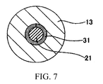
- FIG. 7 is a cross sectional view of an extra high pressure mercury lamp of FIG. 1 , taken along a line VII-VII;
- FIG. 8 is a perspective view showing the structure of a metallic foil with an electrode axis portion and an external lead in a conventional extra high pressure mercury lamp.
- FIG. 9 is a cross sectional view of a schematic structure of a conventional extra high pressure mercury lamp, taken in a tube axis direction.
- FIG. 1 is a cross sectional view of a schematic structure of an extra high pressure mercury lamp according to the present invention, taken in a longitudinal direction of the lamp.
- This extra high pressure mercury lamp 10 includes an arc tube 11 which is made up of a spherical light emission section 12 and rod shape sealing portions 13 , which respectively extend from both ends of the light emission section 12 in a tube axis direction towards the outside thereof, wherein the arc tube 11 is made of quartz glass.
- the sealing portions 13 are formed by, for example, a shrink sealing method, and a cross sectional view thereof is a circle in shape.
- a pair of electrodes 20 which are made of tungsten respectively and face each other, are arranged apart from each other at a distance of 0.5-2.0 mm inside the light emission section 12 . Part of each electrode 20 in a tip end side thereof is projected into the light emission section 12 , and a base portion thereof is held in each sealing portion 13 . Each of the electrodes is electrically connected with each metallic foil 30 buried in each sealing portion 13 . Each metallic foil 30 is made of molybdenum. Each external lead 15 , which projects in a tube axis direction toward the outside thereof from an outer end portion of the sealing portion, is electrically connected to each metallic foil 30 .
- Mercury, rare gas, and halogen gas are enclosed inside the light emission section 12 .
- the amount of mercury enclosed therein is, for example, 0.2 mg/mm 3 or more, so that the mercury vapor pressure in the light emission section 12 may turn into 200 atmospheric pressure or more at time of lighting.
- Rare gas is used for improving the starting nature of the extra high pressure mercury lamp, and, for example, argon gas of 13 kPa is enclosed as the rare gas.
- Halogen gas is used for prolonging the life span of the lamp by using the halogen cycle, and for preventing breakage and devitrification of the light emission section 11 .
- the enclosed amount thereof is suitably adjusted within a range of 10 ⁇ 6 -10 ⁇ 2 ⁇ mol/mm 3 according to the specification of the lamp.
- FIG. 2 shows an enlarged view of an electrode of the extra high pressure mercury lamp shown in FIG. 1 .
- Each electrode 20 of the extra high pressure mercury lamp is made up of a cylindrical electrode axis portion 21 and an electrode main body section 22 , which is formed at the tip of the electrode axis portion 21 .
- the electrode axis portion 21 and the electrode main body section 22 are made of tungsten.
- a coil section 23 is formed in the circumference of the electrode main body section 22 by winding a wire rod made of tungsten therearound. The coil section 23 is provided in order to improve the starting nature of the extra high pressure mercury lamp.
- the projection section 24 is provided so as to make it easy to concentrate an electric discharge arc at time of lighting.
- Such an electrode 20 is arranged in a state where the central axis O of the electrode axis portion 21 is in agreement with the tube axis C of the arc tube while the entire electrode main body section 22 is projects in the sealed space of the light emission section 12 .
- the extra high pressure mercury lamp 10 which has such electrodes 20
- dielectric breakdown is produced between the electrodes 20 so that an electric discharge arc is formed at the projection section 24 of each electrode 20 as the starting point thereof.
- light including visible light of a waveform of 360 to 780 nm is emitted.
- FIG. 3 is a perspective view of the structure of an electrode mount which is made up of a metallic foil and an electrode.
- FIG. 4 is a perspective view of the structure of the metallic foil in a state that is prior to joining the metallic foil to an electrode axis portion.
- the metallic foil 30 includes a cylindrical covering section 31 , which has the shape corresponding to the shape of the electrode axis portion 21 ; an extended portion 32 having a gutter-like shape, which extends in a direction of the tube axis C toward the outside (a direction opposite to the covering section 31 on paper in which FIG.
- the projection width of the main body section 34 is larger than the projection width of the extended portion 32 .
- the covering section 31 is arranged on an outer face of the electrode axis portion 21 , so as to roll up the electrode axis portion 21 , and is fixed, in an integrated fashion, to the electrode axis portion 21 by means such as laser welding or resistance welding.
- an external lead 15 for electric supply shown in FIG. 1 is connected to a base side of the main body section 34 . In such a manner, the electrode mount 40 shown in FIG. 3 is completed.
- FIG. 5 is a perspective view of the structure of the metallic foil in a state that is before forming the covering section is formed.
- the metallic foil 30 A includes a small width section 32 A, which is formed at a predetermined distance from a tip thereof; and large width sections 31 A and 34 A, which are formed so that the small width section 32 A is located therebetween in a longitudinal direction of the metallic foil, which are continuously formed from a tip end side of the small width section 32 A and a base end side thereof respectively, and which extend in width directions of the metallic foil, respectively.
- the small width section 32 A is formed by forming, apart from the tip of the metallic foil 30 A, a pair of cut-out portions 50 , each of which curves towards the central-axis X of the metallic foil 30 A, and has the same shape as each other.
- Oblique side sections 33 A are formed between the small width section 32 A and the large width section 34 A, and the respective oblique side sections 33 A become gradually small in width, as close to the small width section 32 A.
- FIGS. 6A , 6 B, 6 C and 6 D are perspective views for explaining a manufacture method of electrode mount of FIG. 3 .
- FIG. 6A shows a metallic foil in an initial state which is before a covering section is formed.
- FIG. 6B shows the metallic foil in the state where the covering section is formed.
- FIG. 6C shows a step of inserting a base portion of an electrode into the covering section of the metallic foil.
- FIG. 6D shows a completed electrode mount.
- the small width section 32 A is formed approximately in the shape of gutter in a cross sectional view thereof.
- the cylindrical covering section 31 which has an outer diameter slightly larger than that of the electrode axis portion 21 is formed by forming the large width section 31 A.
- both ends of the large width section 31 A in the width direction may be slightly apart from each other.
- a base section 21 A of the electrode axis portion 21 and the covering section 31 of the metallic foil 30 are arranged so as to face each other, and then the electrode axis portion 21 is moved towards the covering section 31 from a side of the base section 21 A of the electrode axis portion 21 so that the base section 21 A of the electrode axis portion 21 is inserted in the covering section 31 .
- the outer circumference of the covering section 31 is irradiated with a laser from the outside of the covering section 31 , so that the covering section 31 is integrally fixed to the electrode axis portion 21 .
- the covering section 31 may be fixed to the electrode axis portion 21 by resistance welding.
- an electrode mount 40 shown in FIG. 6D is obtained.
- the electrode mount 40 produced by such steps is accommodated inside the arc tube forming material, which is made of quartz glass, and then it is air tightly sealed therein by performing a sealing process such as shrink sealing etc., so that the sealing portion 13 shown in FIG. 1 is formed.
- the sealing portion 13 shown in FIG. 1 is formed in the metallic foil 30 , the covering section 31 , the extended portion 32 , the gradually increasing width portion 33 , and the main body section 34 are in close contact with the quartz glass which forms the sealing portion 13 .
- the covering section 31 of the metallic foil 30 is provided between the electrode axis portion 21 and the quartz glass that forms the sealing portion 13 , whereby the electrode axis portion 21 is not in contact with the glass that forms the sealing portion 13 completely, or it is possible to maximally reduce the contact area of the electrode axis portion 21 and the glass.
- the metallic foil 30 that has the gutter shaped-extended portion 32 which extends towards the outside thereof in the tube axis direction and which is not connected with the electrode axis portion 21 following the covering section 31 is buried in the sealing portion 13 , the metallic foil 30 does not come off from the quartz glass which forms the sealing portion 13 . This reason is considered as set forth below, although it is not certain.
- minute gaps are inevitably formed between the electrode axis portion 21 and the quartz glass that forms a sealing portion 13 . Minute gaps are formed between the electrode axis portion 21 and the quartz glass around the electrode axis portion 21 , and between the covering section 31 which covers the circumference of the electrode axis portion 21 , and the quartz glass around the covering section 31 . At time of lighting of the extra high pressure mercury lamp, the high pressure of the light emission section 12 is applied to these minute gaps.
- An extra high pressure mercury lamp (an embodiment) which includes the metallic foil 30 having the structure shown in FIG. 3 and an extra high pressure mercury lamp (comparative example) in which a metallic foil shown in FIG. 3 does not have an extended portion 32 , will be explained below, comparing them with each other.
- the extended portion 32 extends from a back edge of the covering section 31 , and this extended portion 32 is sealed so as to be in close contact with the quartz glass which forms the sealing portion 13 . Therefore, the high pressure in the light emission section 12 at time of lighting is not applied to the angle sections 34 X of the main body section 34 through the above-mentioned minute gaps, so that distortion is not produced in the main body section 34 .
- the main body section 34 and the quartz glass which forms the sealing portion 13 are not separated from each other.
- the comparative example did not have the extended portion 32 which extends from the back edge of the covering section 31 , and has a spread to the width of the main body section 34 immediately from the back edge of the covering section 31 , angle sections 34 X are formed so that stress tends to concentrate on these portion. Consequently, the high pressure at time of lighting in the light emission section 12 is applied to the angle sections 34 X of the main body section 34 through the above-mentioned minute gaps, so that distortion thereof occurs, whereby there is a possibility that the quartz glass which forms the main body section 34 and the sealing portion 13 are separated from each other.
- the metallic foil 30 is buried in the sealing portion 13 , wherein the metallic foil 30 has the structure in which the gradually increasing width portion 33 whose width becomes gradually large towards the outside of the tube axis is formed between the extended portion 32 and the main body section 34 . Therefore, it is expected that distortion of the main body section 34 is further suppressed.
- the gradually increasing width portion 33 is not an indispensable element.
- the metallic foil has the structure only having: the covering section 31 connected to the electrode axis portion 21 so as to roll up the electrode axis portion 21 ; the gutter-shaped extended portion 32 which extends from the covering section 31 towards the outside in the tube axis direction, without being connected to the electrode axis portion 21 ; and the main body section 34 . Even if the lamp is an extra high pressure mercury lamp having the sealing portion 13 in which the above-described metallic foil 30 is buried, the above-mentioned effect is expected.
- An arc tube 11 is 70 mm in full length, and the outer diameter thereof is 10 mm.
- the arc tube 11 is 66 mm 3 in internal volume.
- the amount of mercury enclosed is 0.3 mg/mm 3 .
- a metallic foil 30 is 14 mm in full length and 0.02 mm in thickness.
- An extended portion 32 is in the shape of a gutter.
- the extended portion 32 is 0.5 mm in projection width and 1.4 mm in full length.
- a gradually increasing width portion 33 is 0.4 mm in full length.
- a main body section 34 is 1.5 mm in width and 11 mm in full length.
- An electrode axis portion 21 is ⁇ 0.4 mm in diameter.
- the extra high pressure mercury lamp of the present invention is not limited to the above-mentioned embodiment, and various changes of design are possible.
- the extended portion 32 of the metallic foil 30 is in the shape of a gutter as shown in FIGS. 3 and 4
- the extended portion 32 may be, for example, in the shape of a plate.
- the main body section of the metallic foil may be formed in the omega ( ⁇ ) shape as a whole by forming a slot portion extending in parallel to the tube axis and in the center in a width direction.
Abstract
Description
Claims (3)
Applications Claiming Priority (2)
| Application Number | Priority Date | Filing Date | Title |
|---|---|---|---|
| JP2009-017875 | 2009-01-29 | ||
| JP2009017875A JP2010177014A (en) | 2009-01-29 | 2009-01-29 | Extra-high pressure mercury lamp |
Publications (2)
| Publication Number | Publication Date |
|---|---|
| US20100187993A1 US20100187993A1 (en) | 2010-07-29 |
| US8072145B2 true US8072145B2 (en) | 2011-12-06 |
Family
ID=42353620
Family Applications (1)
| Application Number | Title | Priority Date | Filing Date |
|---|---|---|---|
| US12/656,387 Expired - Fee Related US8072145B2 (en) | 2009-01-29 | 2010-01-28 | Extra high pressure mercury lamp with each electrode held by a sealing portion |
Country Status (3)
| Country | Link |
|---|---|
| US (1) | US8072145B2 (en) |
| JP (1) | JP2010177014A (en) |
| CN (1) | CN101794705A (en) |
Citations (7)
| Publication number | Priority date | Publication date | Assignee | Title |
|---|---|---|---|---|
| JPS6459754A (en) | 1987-08-31 | 1989-03-07 | Toshiba Corp | High pressure sodium lamp |
| JPH027353A (en) | 1988-01-15 | 1990-01-11 | Asea Brown Boveri Ag | High output radiator |
| US6903509B2 (en) | 2002-03-05 | 2005-06-07 | Ushiodenki Kabushiki Kaisha | Ultrahigh pressure discharge lamp of the short arc type with improved metal foil to electrode connection arrangement |
| JP2007280823A (en) | 2006-04-10 | 2007-10-25 | Ushio Inc | Short arc ultra-high pressure discharge lamp |
| JP2008071718A (en) | 2006-09-15 | 2008-03-27 | Shin Kowa Kk | High-pressure discharge lamp |
| WO2009011117A1 (en) | 2007-07-17 | 2009-01-22 | Panasonic Corporation | High pressure discharge lamp, lamp unit employing the high pressure discharge lamp, and projection image display employing the lamp unit |
| KR20090023065A (en) | 2007-08-31 | 2009-03-04 | 우시오덴키 가부시키가이샤 | Excimer lamp |
-
2009
- 2009-01-29 JP JP2009017875A patent/JP2010177014A/en active Pending
-
2010
- 2010-01-19 CN CN201010004598A patent/CN101794705A/en active Pending
- 2010-01-28 US US12/656,387 patent/US8072145B2/en not_active Expired - Fee Related
Patent Citations (10)
| Publication number | Priority date | Publication date | Assignee | Title |
|---|---|---|---|---|
| JPS6459754A (en) | 1987-08-31 | 1989-03-07 | Toshiba Corp | High pressure sodium lamp |
| JPH027353A (en) | 1988-01-15 | 1990-01-11 | Asea Brown Boveri Ag | High output radiator |
| US4983881A (en) | 1988-01-15 | 1991-01-08 | Asea Brown Boveri Ltd. | High-power radiation source |
| US6903509B2 (en) | 2002-03-05 | 2005-06-07 | Ushiodenki Kabushiki Kaisha | Ultrahigh pressure discharge lamp of the short arc type with improved metal foil to electrode connection arrangement |
| JP2007280823A (en) | 2006-04-10 | 2007-10-25 | Ushio Inc | Short arc ultra-high pressure discharge lamp |
| JP2008071718A (en) | 2006-09-15 | 2008-03-27 | Shin Kowa Kk | High-pressure discharge lamp |
| WO2009011117A1 (en) | 2007-07-17 | 2009-01-22 | Panasonic Corporation | High pressure discharge lamp, lamp unit employing the high pressure discharge lamp, and projection image display employing the lamp unit |
| US20100188855A1 (en) | 2007-07-17 | 2010-07-29 | Panasonic Corporation | High-pressure discharge lamp, lamp unit using the same, and projection-type image display device using the lamp unit |
| KR20090023065A (en) | 2007-08-31 | 2009-03-04 | 우시오덴키 가부시키가이샤 | Excimer lamp |
| US7800308B2 (en) | 2007-08-31 | 2010-09-21 | Ushio Denki Kabushiki Kaisha | Excimer lamp |
Also Published As
| Publication number | Publication date |
|---|---|
| JP2010177014A (en) | 2010-08-12 |
| US20100187993A1 (en) | 2010-07-29 |
| CN101794705A (en) | 2010-08-04 |
Similar Documents
| Publication | Publication Date | Title |
|---|---|---|
| TW388059B (en) | High-pressure discharge lamp and manuf acturing method thereof | |
| US6137228A (en) | Metal halide lamps with tungsten coils having varying pitches and inner diameters | |
| US8207673B2 (en) | High-pressure discharge lamp, lamp unit using the same, and projection-type image display device using the lamp unit | |
| US6369509B1 (en) | Short arc lamp with crack-preventing electric mounting arrangement | |
| EP1143485A2 (en) | Discharge lamps, method for producing the same and lamp unit | |
| JP3166526B2 (en) | Short arc discharge lamp | |
| US8072145B2 (en) | Extra high pressure mercury lamp with each electrode held by a sealing portion | |
| US7176631B2 (en) | Ultra high pressure discharge lamp | |
| US6121729A (en) | Metal halide lamp | |
| JP2009193768A (en) | Short arc high-pressure discharge lamp | |
| JP3480453B2 (en) | Short arc type ultra-high pressure discharge lamp | |
| JP4929961B2 (en) | High pressure mercury lamp | |
| US6876151B2 (en) | Discharge lamp and lamp unit | |
| US20120119644A1 (en) | Xenon short arc lamp | |
| JP2004039349A (en) | High-pressure discharge lamp and light source unit | |
| JP4878984B2 (en) | Discharge lamp and discharge lamp manufacturing method | |
| JP4193540B2 (en) | Short arc type ultra high pressure discharge lamp | |
| JP5216934B1 (en) | High pressure discharge lamp and projector using the high pressure discharge lamp | |
| JP2004164996A (en) | Metallic vapor discharge lamp and high pressure mercury-vapor discharge lamp | |
| US10991569B2 (en) | Electrode arrangement for a discharge lamp, gas discharge lamp, protective film and method for providing a protective film on an electrode arrangement | |
| JP4887916B2 (en) | Discharge lamp and metal foil for discharge lamp | |
| JP3290649B2 (en) | Discharge lamp and lamp unit | |
| JP6186677B2 (en) | Excimer lamp | |
| JPH1116537A (en) | Short arc discharge lamp | |
| JP2000003695A (en) | Discharge lamp |
Legal Events
| Date | Code | Title | Description |
|---|---|---|---|
| AS | Assignment |
Owner name: USHIO DENKI KABUSHIKI KAISHA, JAPAN Free format text: ASSIGNMENT OF ASSIGNORS INTEREST;ASSIGNORS:KASAISHI, SHUKI;TSUKAMOTO, TAKUYA;SUGIHARA, NOBUHIKO;AND OTHERS;REEL/FRAME:023925/0377 Effective date: 20100112 |
|
| ZAAA | Notice of allowance and fees due |
Free format text: ORIGINAL CODE: NOA |
|
| ZAAB | Notice of allowance mailed |
Free format text: ORIGINAL CODE: MN/=. |
|
| FEPP | Fee payment procedure |
Free format text: PAYOR NUMBER ASSIGNED (ORIGINAL EVENT CODE: ASPN); ENTITY STATUS OF PATENT OWNER: LARGE ENTITY |
|
| STCF | Information on status: patent grant |
Free format text: PATENTED CASE |
|
| FPAY | Fee payment |
Year of fee payment: 4 |
|
| MAFP | Maintenance fee payment |
Free format text: PAYMENT OF MAINTENANCE FEE, 8TH YEAR, LARGE ENTITY (ORIGINAL EVENT CODE: M1552); ENTITY STATUS OF PATENT OWNER: LARGE ENTITY Year of fee payment: 8 |
|
| FEPP | Fee payment procedure |
Free format text: MAINTENANCE FEE REMINDER MAILED (ORIGINAL EVENT CODE: REM.); ENTITY STATUS OF PATENT OWNER: LARGE ENTITY |
|
| LAPS | Lapse for failure to pay maintenance fees |
Free format text: PATENT EXPIRED FOR FAILURE TO PAY MAINTENANCE FEES (ORIGINAL EVENT CODE: EXP.); ENTITY STATUS OF PATENT OWNER: LARGE ENTITY |
|
| STCH | Information on status: patent discontinuation |
Free format text: PATENT EXPIRED DUE TO NONPAYMENT OF MAINTENANCE FEES UNDER 37 CFR 1.362 |
|
| FP | Lapsed due to failure to pay maintenance fee |
Effective date: 20231206 |