US8071967B2 - Trolley wire wear measuring device using binary operated images - Google Patents
Trolley wire wear measuring device using binary operated images Download PDFInfo
- Publication number
- US8071967B2 US8071967B2 US12/440,876 US44087607A US8071967B2 US 8071967 B2 US8071967 B2 US 8071967B2 US 44087607 A US44087607 A US 44087607A US 8071967 B2 US8071967 B2 US 8071967B2
- Authority
- US
- United States
- Prior art keywords
- trolley wire
- image
- worn portion
- binary
- width
- Prior art date
- Legal status (The legal status is an assumption and is not a legal conclusion. Google has not performed a legal analysis and makes no representation as to the accuracy of the status listed.)
- Expired - Fee Related, expires
Links
- 238000000034 method Methods 0.000 claims abstract description 111
- 238000001514 detection method Methods 0.000 claims description 9
- 238000004458 analytical method Methods 0.000 claims description 7
- 238000005259 measurement Methods 0.000 description 48
- 238000003708 edge detection Methods 0.000 description 12
- 238000005286 illumination Methods 0.000 description 9
- 238000012545 processing Methods 0.000 description 9
- 238000010586 diagram Methods 0.000 description 7
- 230000006870 function Effects 0.000 description 6
- DGAQECJNVWCQMB-PUAWFVPOSA-M Ilexoside XXIX Chemical compound C[C@@H]1CC[C@@]2(CC[C@@]3(C(=CC[C@H]4[C@]3(CC[C@@H]5[C@@]4(CC[C@@H](C5(C)C)OS(=O)(=O)[O-])C)C)[C@@H]2[C@]1(C)O)C)C(=O)O[C@H]6[C@@H]([C@H]([C@@H]([C@H](O6)CO)O)O)O.[Na+] DGAQECJNVWCQMB-PUAWFVPOSA-M 0.000 description 5
- 229910052708 sodium Inorganic materials 0.000 description 5
- 239000011734 sodium Substances 0.000 description 5
- 238000012360 testing method Methods 0.000 description 5
- 238000000605 extraction Methods 0.000 description 4
- 230000003287 optical effect Effects 0.000 description 4
- 239000000284 extract Substances 0.000 description 3
- 230000015654 memory Effects 0.000 description 3
- 230000002349 favourable effect Effects 0.000 description 2
- 241000219122 Cucurbita Species 0.000 description 1
- 235000009852 Cucurbita pepo Nutrition 0.000 description 1
- 230000002159 abnormal effect Effects 0.000 description 1
- 238000006243 chemical reaction Methods 0.000 description 1
- 230000008602 contraction Effects 0.000 description 1
- 230000000694 effects Effects 0.000 description 1
- 238000001914 filtration Methods 0.000 description 1
- 238000009499 grossing Methods 0.000 description 1
- 238000003384 imaging method Methods 0.000 description 1
- 239000012212 insulator Substances 0.000 description 1
- JEIPFZHSYJVQDO-UHFFFAOYSA-N iron(III) oxide Inorganic materials O=[Fe]O[Fe]=O JEIPFZHSYJVQDO-UHFFFAOYSA-N 0.000 description 1
- 239000002932 luster Substances 0.000 description 1
- 238000012423 maintenance Methods 0.000 description 1
- 230000005855 radiation Effects 0.000 description 1
- 239000004071 soot Substances 0.000 description 1
- 230000003936 working memory Effects 0.000 description 1
Images


Classifications
-
- G—PHYSICS
- G01—MEASURING; TESTING
- G01B—MEASURING LENGTH, THICKNESS OR SIMILAR LINEAR DIMENSIONS; MEASURING ANGLES; MEASURING AREAS; MEASURING IRREGULARITIES OF SURFACES OR CONTOURS
- G01B11/00—Measuring arrangements characterised by the use of optical techniques
- G01B11/24—Measuring arrangements characterised by the use of optical techniques for measuring contours or curvatures
-
- B—PERFORMING OPERATIONS; TRANSPORTING
- B60—VEHICLES IN GENERAL
- B60M—POWER SUPPLY LINES, AND DEVICES ALONG RAILS, FOR ELECTRICALLY- PROPELLED VEHICLES
- B60M1/00—Power supply lines for contact with collector on vehicle
- B60M1/12—Trolley lines; Accessories therefor
- B60M1/28—Manufacturing or repairing trolley lines
-
- G—PHYSICS
- G01—MEASURING; TESTING
- G01B—MEASURING LENGTH, THICKNESS OR SIMILAR LINEAR DIMENSIONS; MEASURING ANGLES; MEASURING AREAS; MEASURING IRREGULARITIES OF SURFACES OR CONTOURS
- G01B11/00—Measuring arrangements characterised by the use of optical techniques
- G01B11/16—Measuring arrangements characterised by the use of optical techniques for measuring the deformation in a solid, e.g. optical strain gauge
-
- G—PHYSICS
- G01—MEASURING; TESTING
- G01M—TESTING STATIC OR DYNAMIC BALANCE OF MACHINES OR STRUCTURES; TESTING OF STRUCTURES OR APPARATUS, NOT OTHERWISE PROVIDED FOR
- G01M5/00—Investigating the elasticity of structures, e.g. deflection of bridges or air-craft wings
- G01M5/0033—Investigating the elasticity of structures, e.g. deflection of bridges or air-craft wings by determining damage, crack or wear
Definitions
- the present invention relates to a device for measuring wear of a pantograph contact surface of a trolley wire, and more particularly to a wear measuring device that determines a width of the pantograph contact surface through a photography image of the trolley wire then measures a thickness of the trolley wire from this width.
- a pantograph current collector On the trolley wire that supplies a power to a car of an electric railroad or railway, contact with a pantograph current collector (a pantograph) occurs each time the car passes. Because of this, the trolley wire is gradually worn out during an operation of the electric railway car, and if a replacement is not made, a rupture or breaking finally occurs and causes an accident. A wear limit is then set for the trolley wire. By using the wear limit as an index of a change of the trolley wire, the trolley wire is changed and safety of the electric railway car is secured.
- a method of measuring the wear of the trolley wire there are mainly two methods; one is a method that directly measures a thickness of the trolley wire, the other is a method that measures a width of a trolley wire worn portion and transforms this wear width into the thickness of the trolley wire.
- the thickness of the trolley wire As one method that directly measures the thickness of the trolley wire, there is a method that measures the thickness of the trolley wire using a ruler such as a vernier caliper. This is a method that measures the thickness of the trolley wire of a portion which an operator intends to measure, using the ruler such as the vernier caliper by hand. With this method, the thickness of the trolley wire to be measured can be surely determined. On the other hand, this measurement requires manpower and cannot be automated, thus it is difficult to measure the thickness of a long distance section.
- the other method that directly measures the thickness of the trolley wire there is a method using an optical sensor.
- this method it is possible to continuously measure the thickness of the trolley wire. However, because of contact with the trolley wire, a low speed operation is required.
- the method that measures the width of the trolley wire worn portion there is a method that measures the trolley wire worn portion by applying sodium lamp or laser light (refer to a Patent Document 1). This is a method that uses the following relation; a lower portion of the trolley wire has a round gourd shape in cross section, and, as the trolley wire is shaved by the wear and becomes flatter, the width of the shaved portion becomes wider. Then, the thickness of the shaved portion of the trolley wire is transformed from the wear width.
- positions of a light source and a line sensor of a light receiving part are precisely adjusted so that a reflected light from the trolley wire worn portion is received with regular reflection when applying the sodium lamp or laser light from the light source, and the trolley wire worn portion is changed into a whiteout state by way of imaging and capturing an intense light by the regular reflection, then the width of the trolley wire worn portion is measured from a width of the whiteout portion which receives the intense light.
- This manner is a non-contact manner, thus a high speed operation is possible.
- this manner is susceptible to noises such as a clamp that pinches the trolley wire and a structure which appears on the background. Further, in a case where a wrong measurement result is obtained due to some noises, there is no way to verify the result. Then, with regard to the portion of the problem as the trolley wire wear measurement, it is verified using the method directly measuring the thickness of the trolley wire in the end. In addition, it is required that the regular reflection is received by precisely adjusting an application direction and a focus of the light source and a light-receiving direction of the light receiving device.
- Patent Document 1 Japanese Patent Application Kokai Publication No. 10-194015
- the measuring method of the wear of the trolley wire there are the methods; the method that directly measures the thickness of the trolley wire using the ruler such as the vernier caliper, the method that directly measures the thickness of the trolley wire using the optical sensor, and the method that measures the width of the trolley wire worn portion by applying the sodium lamp or the laser light and transforms the width of the trolley wire worn portion into the thickness of the trolley wire.
- each of the methods has the following problems.
- this manner is susceptible to noises such as the clamp that pinches the trolley wire and the structure which appears on the background, and in the case where the wrong measurement result is obtained due to some noises, there is no way to verify the result.
- the portion of the problem as the trolley wire wear measurement there is no way to ascertain its cause. Then, such a needless work that the thickness is verified using the method directly measuring the thickness of the trolley wire, is needed in the end.
- the regular reflection is received by precisely adjusting the application direction and the focus of the light source and the light-receiving direction of the light receiving device.
- the trolley wire worn portion is measured using reflected light of the illumination, the measurement is limited to the night time when the sky of the background is dark and the trolley wire worn portion becomes blight.
- a line sensor is placed in a direction of a scanning line perpendicular to a laying direction of a trolley wire, and shoots a pantograph contact surface of the trolley wire while moving along the trolley wire.
- Luminance signals of scanning lines, obtained by the line sensor are arranged in time series, and a line sensor image is created.
- a removal etc. of background parts from this line sensor image or a binary operated line sensor image only a trolley wire part is extracted, and its binary operation process is performed. Edges of a trolley wire worn portion are detected from this binary operated line sensor image, and an overall width of the trolley wire is determined from this edge data, then a wear measurement value of the trolley wire is obtained.
- the present invention has following systems.
- a trolley wire wear measuring device comprises: a means that gets a line sensor image in which luminance signals of scanning lines, obtained by a line sensor, are arranged in time series, the line sensor is placed in a direction of the scanning line perpendicular to a laying direction of a trolley wire of a wear measurement target and shoots a pantograph contact surface (a worn portion) of the trolley wire while moving along the trolley wire; a binary operation process means which performs a binary operation process to the line sensor image and gets a binary operated line sensor image; a removal means that removes a background part from the binary operated line sensor image; a remaining-image binary operation process means that gets a binary operated image in which a worn portion of the trolley wire is emphasized by the binary operation process of the background part-removed image; an edge detection means that detects edges of both sides of the worn portion on the binary operated image performed with the remaining-image binary operation process; and a worn portion width calculation means that calculates a point-to-point distance of the both side edges as a whole width
- a trolley wire wear measuring device comprises: a means that gets a line sensor image in which luminance signals of scanning lines, obtained by a line sensor, are arranged in time series, the line sensor is placed in a direction of the scanning line perpendicular to a laying direction of a trolley wire of a wear measurement target and shoots a pantograph contact surface (a worn portion) of the trolley wire while moving along the trolley wire; a means that extracts both side surfaces of the trolley wire from the line sensor image; an area-inside binary operation process means that gets a binary operated image in which a worn portion of the trolley wire is emphasized by performing the binary operation process to an area inside the both side surfaces on the line sensor image; an edge detection means that detects edges of both sides of the worn portion on the binary operated image performed with the area-inside binary operation process; and a worn portion width calculation means that calculates a point-to-point distance of the both side edges as a whole width of the worn portion of the trolley wire on the binary operated image and determines a worn portion width of the trolley
- a trolley wire wear measuring device comprises: a means that gets a pair of line sensor images in which luminance signals of scanning lines, obtained by two line sensors, are arranged in time series, the two line sensors are placed in a direction of the scanning line perpendicular to a laying direction of a trolley wire of a wear measurement target, and one line sensor shoots a pantograph contact surface (a worn portion) of a light-applied trolley wire, and the other line sensor shoots the pantograph contact surface (the worn portion) of a non-light-applied trolley wire, while moving along the trolley wire; a differential process means that gets a line sensor image in which an illuminated worn area of the trolley wire is emphasized by getting a difference of luminance between the pair of line sensor images; a binary operation process means that gets a binary operated image in which a worn portion of the trolley wire is emphasized by performing the binary operation process to the line sensor image performed with the differential process; an edge detection means that detects edges of both sides of the worn portion on the binary operated image; and a worn
- the worn portion width calculation means has a height detection means that determines a height of the trolley wire, viewed from the line sensor, through the whole width and a line sensor's camera parameter; and a worn portion actual width calculation means that determines an actual width of the trolley wire worn portion through the whole width and the height of the trolley wire.
- the trolley wire wear measuring device further comprises: a means that extracts a portion of the edge image, which corresponds to the trolley wire, as a group, on the binary operated line sensor image in which the edges of the trolley wire worn portion are detected; and a means that extracts a portion that continues from an upper part to a lower part on the image as a trolley wire image for each group, and removes the other groups that locally exist as a noise.
- the edge detection means has a means that performs extraction of a difference of positions between left and right side edges as the width of the worn portion for each line on the binary operated image, the extraction is performed for all lines on the binary operated image; a means that gets a difference between a maximum width and a minimum width for the each edge width of the all lines on the image; and a means that judges the wear of the worn portion to be waved wear, when the difference between the maximum and minimum widths is large.
- the binary operation process means has a means which draws a histogram of luminance for the whole of the image, and judges the image to be an image in which saturation occurs, when luminance pixels in a high level band exceed a threshold value that is determined from a normal trolley wire reflection area.
- the worn portion width calculation means has a means that judges the image to be an image in which saturation occurs, when the width of the trolley wire worn portion is greater than a main line of the trolley wire.
- the binary operation process means has a means which judges that when a size of the trolley wire becomes an area that exceeds an experimentally determined threshold value, this part as a background image is binary-operated and comes out, and removes this part from the trolley wire image.
- the trolley wire wear measuring device further comprises: a means that gets an overlay display image in which the edge image detected by the edge detection means is overlaid on the line sensor image.
- the trolley wire wear measuring device further comprises: a means that removes noises from the binary operated image obtained by the binary operation process means.
- the binary operation process means automatically sets a threshold value of the binary operation process by a discrimination analysis binary operation method.
- FIG. 1 is a system diagram of a wear measuring device of a trolley wire showing an embodiment 1 of the present invention.
- FIG. 2 is a flow chart of a width measurement of a trolley wire worn portion (the embodiment 1).
- FIG. 3 is a functional system diagram of the wear measuring device of the trolley wire (the embodiment 1).
- FIG. 4 are examples of removal of sky parts and detection of an edge, from a binary line sensor image.
- FIG. 5 are examples of detection of a side of the trolley wire.
- FIG. 6 is a flow chart of the width measurement of the trolley wire worn portion (an embodiment 2).
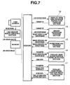
- FIG. 7 is a functional system diagram of the wear measuring device of the trolley wire (the embodiment 2).
- FIG. 8 is a system diagram of the wear measuring device of the trolley wire showing an embodiment 3 of the present invention.
- FIG. 9 are examples of a light-applied trolley wire image, a non-light-applied trolley wire image, and a differential image between them.
- FIG. 10 is a flow chart of the width measurement of the trolley wire worn portion (an embodiment 3).
- FIG. 11 is a functional system diagram of the wear measuring device of the trolley wire (the embodiment 3).
- FIG. 12 is an example of a histogram of a normal trolley wire wear image.
- FIG. 13 is an example of a histogram of a wear image in a saturation state.
- FIG. 14 is an example of an image when the saturation appears.
- FIG. 1 is a system diagram of a wear measuring device of a trolley wire, of an embodiment of the present invention, which performs the wear measurement of the trolley wire during daytime.
- a test car 1 collects current from a trolley wire 3 through a pantograph 2 that is mounted on a roof of the car, and is capable of running on a rail along the trolley wire 3 by a motor drive of wheels, same as a passenger car.
- This test car 1 is provided with a line sensor 5 and an illumination lamp 6 , as a photography image input means of the trolley wire 3 , on the roof.
- a measurement computer 7 and a recording device 8 are installed in the car.
- the line sensor 5 is placed in a direction of a scanning line perpendicular to a laying direction of the trolley wire of a wear measurement target, and shoots a pantograph contact surface of the trolley wire while moving along the trolley wire. For this reason, the line sensor 5 is installed vertically so that the line sensor 5 faces in an upward direction on the roof of the test car 1 . Further, the line sensor 5 is installed in such a direction that the scanning line is perpendicular to a travelling direction of the test car 1 (i.e. the trolley wire laying direction) and the scanning line crosses the trolley wire 3 .
- the illumination lamp 6 it is not limited as long as a shooting area of the trolley wire 3 and its close area with the shooting area being the center can be illuminated through the line sensor 5 , then a normal illumination lamp is used.
- the measurement computer 7 inputs luminance signals of the scanning line, which is obtained through the line sensor 5 by the travel of the test car 1 . Further, the measurement computer 7 arranges these luminance signals in time series, and creates a line sensor image (a plane image), then stores them, as the photography image of the trolley wire 3 , in the recording device 8 such as a hard disk in succession.
- the measurement computer 7 or other computers determines a width of a worn portion of the trolley wire 3 by an image processing of the line sensor image stored in the recording device 8 , and determines a thickness of the trolley wire 3 from this determined width of the worn portion.
- FIG. 2 A flow chart that determines this trolley wire worn portion width is shown in FIG. 2 .
- Computer resources for realizing this process and a functional system by software are shown in FIG. 3 .
- FIG. 4 A flow chart that determines this trolley wire worn portion width is shown in FIG. 2 .
- the line sensor image is stored in the recording device 8 through the line sensor 5 and the measurement computer 7 .
- the line sensor image is created from an image signal obtained by the line sensor 5 in a line sensor image creating section 7 A of the measurement computer 7 , then is written in a predetermined memory area 8 A of the recording device 8 .
- the line sensor image saved in the memory area 8 A of the recording device 8 is transferred to a memory 11 such as a working memory.
- the trolley wire becomes black and a background portion (sky parts) becomes white.
- the worn portion of the trolley wire is a portion that is shaved by the pantograph, it has a high luster as compared with an unworn portion. Therefore, the trolley wire worn portion is shot as a band section of a different luminance level, as compared with the background portion, even on the line sensor image (refer to FIG. 4A ).
- a binary operation process section 12 in FIG. 3 sets a threshold value to separate the trolley wire worn portion (the pantograph contact surface) shot as the band section from other background portions (such as the sky parts and existing structures), and performs the binary operation process to the line sensor image using the threshold value, then emphasizes the worn portion of the trolley wire (hereinafter called “binary operated line sensor image”).
- the whole of a trolley wire side surface is black, and the background portion is white on the binary operated line sensor image (refer to FIG. 4B ).
- the threshold value used in the binary operation process could be manually set if necessary, the threshold value can be set using a discrimination analysis binary operation method in order to respond to a shift of the trolley wire or a difference in intensity of a reflected light from the trolley wire.
- This discrimination analysis binary operation method is a method that automatically determines the threshold value in accordance with the image by a computer processing. More specifically, there is a group of pixels (hereinafter called “class”) that has a luminance level within a certain range and gathers in a histogram of the each image, and the threshold value is determined so that variance ratio of intraclass variance and interclass variance with respect to the background and a pattern area becomes a maximum upon the binary operation. With this method, a relatively favorable threshold value can be determined on any image, and the worn portion can be extracted. In the following embodiments as well, the threshold value of the binary operation process can be automatically set using the discrimination analysis binary operation method.
- the sky comes out on the background ( FIG. 4A ). Furthermore, its luminance is greater than that of the worn portion of the trolley wire. Because of this, the trolley wire becomes black upon the binary operation process ( FIG. 4B ). That is, in a case of the binary operation process to the whole of the line sensor image, the sky becomes white and the trolley wire becomes black.
- a sky-removal process section 13 in FIG. 3 performs filtering so that a part that becomes white by the binary operation process is removed with respect to an initial image.
- the sky parts are then removed, and only a trolley wire image can remain ( FIG. 4C ).
- a binary operation process section 14 in FIG. 3 further performs the binary operation to the above image (a remaining image) in which “the sky parts” is removed.
- a worn portion surface of the trolley wire then appears, and a binary operated line sensor image in which the trolley wire worn portion is white and the background portion is black, is obtained ( FIG. 4D ).
- a noise removal process section 15 in FIG. 3 removes these noises through an image noise removal method using an expansion of the binary operation process, a contraction processing manner and a median filter or a smoothing filter.
- edge points they can be detected as follows; in a case where a search is carried out from left hand side of a certain line, a point that changes from black of the background to white of the worn portion is regarded as an edge point of a left side of the worn portion and a point that changes from white of the worn portion to black of the background is regarded as an edge point of a right side of the worn portion.
- a trolley wire worn portion edge detection section 16 in FIG. 3 performs this process from an upper part to a lower part of the image for each line, and detects the edges of the trolley wire worn portion of one binary operated line sensor image.
- a trolley wire worn portion width calculation section 17 in FIG. 3 calculates a point-to-point distance of the both side edges on the one scanning line of the line sensor as the width on the image of the trolley wire worn portion by using the edge data of the both sides of the trolley wire worn portion which is detected from the binary operated line sensor image. With respect to this calculation, an actual width of the worn portion is determined by detecting an overall width of the trolley wire and performing a calculation of a height of the trolley wire.
- a thickness of the trolley wire is previously set, and the overall width of the trolley wire is extracted and calculated through the image processing by the input line sensor image, and further a conversion is made from this overall width value and an image resolution (mm/pixel) that is a degree of an actual size (mm) with respect to a line sensor's camera parameter (a lens focus distance, a sensor width, a sensor pixel number and one pixel (pixel)), then the height of the trolley wire, viewed from the line sensor, is calculated.
- an image resolution mm/pixel
- the wear of the trolley wire can be measured by way of shooting under the sunlight during daytime.
- the trolley wire side surface is shot as the black portion due to rust or soot.
- the trolley wire worn portion is shot as the white, as compared with the side surface, by applying strong illumination ( FIG. 5A ).
- the trolley wire worn portion exists in a sandwiched state between the black lines of the trolley wire side surfaces in the removal of the sky parts from “the binary operated line sensor image” in the embodiment 1, the trolley wire side surface is extracted first, then only the white portion existing inside the side surface is extracted ( FIG. 5B ).
- FIG. 6 A flow chart of this process is shown in FIG. 6 .
- the trolley wire side surface is extracted from the line sensor image obtained (S 8 ), and a binary operation process is executed to an area inside this side surface (S 9 ), which are different from FIG. 2 .
- a system of this device is shown in FIG. 7 .
- a trolley wire side surface extraction process section 18 is provided instead of the binary operation process section 12 and the sky-removal process section 13 .
- FIG. 10 A flow chart of this process is shown in FIG. 10 .
- An image shot by the line sensor 5 A is obtained (S 10 ), and an image shot by the line sensor 5 B is obtained (S 11 ), then by performing a differential operation of the both images, the line sensor image in which the illuminated worn area is emphasized, is obtained (S 12 ), which are different from FIG. 2 .
- a system of this device is shown in FIG. 11 .
- the line sensor 5 A and the line sensor 5 B are provided, and a differential process section 19 that gets the difference from these line sensor images is provided.
- wave wear As one of the wear state of the trolley wire, there is wear that has a wavelike worn portion (hereinafter called “waved wear”).
- waved wear island worn portions, which are scattered, appear even on the binary operated image, and there is a case where such an abnormal output that a proper measurement of the worn portion width cannot be carried out and the worn portion width suddenly narrows appears.
- the waved wear is discriminated detected, and various information, such as the frequency and a position of occurrence of the waved wear on the trolley wire, is obtained.
- the worn portion width determined in “the calculation process of the trolley wire worn portion width” in the embodiment 1 etc. is used. Then by detecting as to whether a difference between a portion having a largest worn portion width and a portion having a smallest worn portion width exceeds a threshold value to the edge detection image of the trolley wire worn portion, a worn surface having the wave, which is the distinction of the waved wear, is judged to be the waved wear.
- a white portion (corresponding to the trolley wire) of the edge image is sorted and the edge image is extracted as a group to the binary operated line sensor image in which the edge of the trolley wire worn portion is detected. And a group that continues from the upper part to the lower part of the screen is judged to be the trolley wire, and then only the trolley wire is extracted by removing the other existing structures such as the clamps and insulators which are locally present.
- the trolley wire worn portion edge detection section 16 has a trolley wire extracting function.
- a state of this luminance variation does not appear in general.
- pixels in a high level band exceed a threshold value that is determined from a normal trolley wire reflection area in the image in the luminance histogram of the image, it is judged to be the image in which the saturation occurs, and the error is output.
- a high luminance pixel distinction process is added to the binary operated images by the binary operation processes (S 4 , S 9 and S 2 ) in the flow charts in FIGS. 2 , 6 and 10 . And when the high luminance pixels are judged, the error output is obtained. Further, in the systems of the devices in FIGS. 3 , 7 and 11 , the noise removal process section 15 has a saturation error handling function.
- a trolley wire width distinction process is added in the flow charts in FIGS. 2 , 6 and 10 . And in a case of the image in which the worn portion is greater than the main line of the trolley wire, the error is output. Further, in the systems of the devices in FIGS. 3 , 7 and 11 , the trolley wire worn portion width calculation section 17 has the saturation error handling function.
- the saturation is detected and the wear measurement error can be reduced.
- the white portion becomes an area that exceeds an experimentally determined threshold value.
- the white portion is judged that the background is binary-operated and comes out, and all of the white is turned to the black, then it is removed from the trolley wire image.
- a trolley wire existence distinction process is added in the flow charts in FIGS. 2 , 6 and 10 . And in a case of the area in which the white portion exceeds the threshold value, the error is output. Further, in the systems of the devices in FIGS. 3 , 7 and 11 , the binary operation process sections 12 and 14 have a trolley wire existence judgment handling function.
- an overlay image display section is added as an image display handling function of a monitor.
- the wear measuring device ensures the wear measurement over the entire section of the trolley wire and facilitates the wear measurement, and further is capable of performing the measurement during daytime, without being affected by the structures existing around the trolley wire. Specific effects are the following.
- the wear width of the trolley wire can be measured without inputting the height parameter of the trolley wire from an outside.
- the favorable threshold value can be determined regardless of the variations of a shooting luminance due to the shift etc. of the trolley wire, then the more correct wear measurement can be performed.
Landscapes
- Engineering & Computer Science (AREA)
- Physics & Mathematics (AREA)
- General Physics & Mathematics (AREA)
- Manufacturing & Machinery (AREA)
- Mechanical Engineering (AREA)
- Aviation & Aerospace Engineering (AREA)
- Length Measuring Devices By Optical Means (AREA)
Abstract
Description
Claims (10)
Applications Claiming Priority (3)
| Application Number | Priority Date | Filing Date | Title |
|---|---|---|---|
| JP2006273524A JP4973108B2 (en) | 2006-10-05 | 2006-10-05 | Trolley wire wear measuring device |
| JP2006-273524 | 2006-10-05 | ||
| PCT/JP2007/065835 WO2008044389A1 (en) | 2006-10-05 | 2007-08-14 | Trolley wire wear measuring device |
Publications (2)
| Publication Number | Publication Date |
|---|---|
| US20090320554A1 US20090320554A1 (en) | 2009-12-31 |
| US8071967B2 true US8071967B2 (en) | 2011-12-06 |
Family
ID=39282598
Family Applications (1)
| Application Number | Title | Priority Date | Filing Date |
|---|---|---|---|
| US12/440,876 Expired - Fee Related US8071967B2 (en) | 2006-10-05 | 2007-08-14 | Trolley wire wear measuring device using binary operated images |
Country Status (7)
| Country | Link |
|---|---|
| US (1) | US8071967B2 (en) |
| EP (1) | EP2071277B1 (en) |
| JP (1) | JP4973108B2 (en) |
| KR (1) | KR101214645B1 (en) |
| CN (1) | CN101529198B (en) |
| RU (1) | RU2416068C2 (en) |
| WO (1) | WO2008044389A1 (en) |
Cited By (3)
| Publication number | Priority date | Publication date | Assignee | Title |
|---|---|---|---|---|
| US9637005B2 (en) * | 2012-03-30 | 2017-05-02 | Caterpillar Inc. | Display conveying trolley position to operator |
| RU187243U1 (en) * | 2018-06-06 | 2019-02-26 | Акционерное общество "Фирма ТВЕМА" | CONTACT NETWORK DEVICE |
| US11874314B2 (en) | 2022-02-09 | 2024-01-16 | Caterpillar Inc. | Electrical contact wear monitoring system |
Families Citing this family (44)
| Publication number | Priority date | Publication date | Assignee | Title |
|---|---|---|---|---|
| NZ582938A (en) * | 2007-08-06 | 2011-07-29 | Qr Ltd | Pantograph damage and wear monitoring system |
| JP4433030B2 (en) * | 2007-10-01 | 2010-03-17 | ブラザー工業株式会社 | Image processing apparatus and control program for image processing apparatus |
| JP5287177B2 (en) * | 2008-11-27 | 2013-09-11 | 株式会社明電舎 | Trolley wire wear and displacement measuring device by image processing |
| JP5418176B2 (en) * | 2009-01-22 | 2014-02-19 | 株式会社明電舎 | Pantograph height measuring device and calibration method thereof |
| JP5298929B2 (en) * | 2009-02-23 | 2013-09-25 | 株式会社明電舎 | Overhead line inspection device |
| JP5244677B2 (en) * | 2009-04-03 | 2013-07-24 | 株式会社日立ハイテクノロジーズ | Trolley wire wear amount detection optical system and trolley wire wear amount measuring device |
| JP5244676B2 (en) * | 2009-04-03 | 2013-07-24 | 株式会社日立ハイテクノロジーズ | Trolley wire wear amount detection optical system and trolley wire wear amount measuring device |
| DE102009043215A1 (en) * | 2009-09-28 | 2011-05-19 | Siemens Aktiengesellschaft | Method and arrangement for controlling pantographs, clearance profiles and horizontal and vertical contact wire position on vehicle bodies |
| CN101858731B (en) * | 2010-06-28 | 2012-01-25 | 成都主导科技有限责任公司 | Device for automatically online-detecting abrasion of pantograph pan of locomotive |
| EP2404777B1 (en) * | 2010-07-07 | 2015-04-29 | ALSTOM Transport Technologies | A device for monitoring condition of a railway supply |
| IT1401952B1 (en) * | 2010-09-22 | 2013-08-28 | Henesis S R L | SYSTEM AND METHOD FOR PANTOGRAPH MONITORING. |
| RU2486466C2 (en) * | 2011-05-03 | 2013-06-27 | Общество с ограниченной ответственностью "Мобильные Системы Диагностики Холдинг" (ООО "МСД Холдинг") | Method for automatic measurement of contact wire wear (wires of catenary system) |
| JP5811637B2 (en) | 2011-06-30 | 2015-11-11 | 株式会社明電舎 | Trolley wire wear measuring device by image processing |
| JP5776378B2 (en) * | 2011-06-30 | 2015-09-09 | 株式会社明電舎 | Crossover measuring device by image processing |
| JP5585790B2 (en) * | 2011-09-27 | 2014-09-10 | 日立建機株式会社 | Electric drive dump truck |
| JP5585791B2 (en) * | 2011-09-27 | 2014-09-10 | 日立建機株式会社 | Electric drive dump truck |
| CN102507600B (en) * | 2011-11-08 | 2013-06-05 | 南京大学 | Automatic detection device for wear of pantograph slide plate of high-speed locomotive |
| US9108571B2 (en) | 2011-12-12 | 2015-08-18 | Google Inc. | Method, system, and computer program product for image capture positioning using a pattern of invisible light |
| FR2990389B1 (en) * | 2012-05-11 | 2015-01-09 | Edmond Briand | SYSTEM AND METHOD FOR MEASURING THE POSITION OF THE CONTACT WIRE OF A CATENARY WITH RESPECT TO A RAILWAY |
| CN103046442B (en) * | 2012-12-18 | 2015-03-11 | 北京二七轨道交通装备有限责任公司 | Grinding wagon laser positioning device and grinding wagon |
| FR3001416B1 (en) * | 2013-01-29 | 2015-02-27 | Sncf | DEVICE FOR DETECTING THE WEAR OF A CATENARY CONTACT WIRE |
| DE102013207271A1 (en) * | 2013-04-22 | 2014-10-23 | Schunk Bahn- Und Industrietechnik Gmbh | Sanding strip, wear detection system and method for wear detection |
| JP2014228383A (en) * | 2013-05-22 | 2014-12-08 | 株式会社神戸製鋼所 | Protrusion detecting method, protrusion detecting device, and method for rolling bar steel material |
| US9480860B2 (en) | 2013-09-27 | 2016-11-01 | Varian Medical Systems, Inc. | System and methods for processing images to measure multi-leaf collimator, collimator jaw, and collimator performance utilizing pre-entered characteristics |
| JP6206957B2 (en) * | 2013-09-27 | 2017-10-04 | 株式会社日立ハイテクファインシステムズ | Trolley wire measuring device and trolley wire measuring method |
| JP6424362B2 (en) * | 2014-09-26 | 2018-11-21 | 株式会社明電舎 | Filament measurement apparatus and method thereof |
| JP6632130B2 (en) * | 2016-02-22 | 2020-01-15 | 三菱重工エンジニアリング株式会社 | Wear degree information acquisition device, wear degree information acquisition method, vehicle, and program |
| CN109269403B (en) * | 2017-07-17 | 2020-02-04 | 成都唐源电气股份有限公司 | Contact net lead abrasion measuring method and device based on machine vision |
| CN109269415B (en) * | 2017-07-17 | 2020-02-18 | 成都唐源电气股份有限公司 | Contact net lead abrasion measuring method and device based on multi-path camera |
| CN107702646A (en) * | 2017-10-11 | 2018-02-16 | 成都国铁电气设备有限公司 | A kind of contact net Abrasion detecting method and system |
| JP6920979B2 (en) * | 2017-12-25 | 2021-08-18 | 株式会社明電舎 | Overhead wire fitting detection device and method |
| CN110118540B (en) * | 2018-02-05 | 2021-03-12 | 宜达工程设计(天津)有限责任公司 | A method for contact line wear detection |
| JP6845169B2 (en) * | 2018-03-09 | 2021-03-17 | 株式会社東芝 | Image processing equipment, image processing methods and programs |
| JP6935350B2 (en) * | 2018-03-19 | 2021-09-15 | 日立建機株式会社 | Surveillance device and trolley type vehicle |
| RU2714076C2 (en) * | 2018-07-05 | 2020-02-12 | ОБЩЕСТВО С ОГРАНИЧЕННОЙ ОТВЕТСТВЕННОСТЬЮ "НАУЧНО-ПРОИЗВОДСТВЕННОЕ ПРЕДПРИЯТИЕ "Когерент" (ООО "НПП "Когерент") | Contact wire parameters measuring device |
| RU2689564C1 (en) * | 2018-08-08 | 2019-05-28 | Общество с ограниченной ответственностью "Мобильные Системы Диагностики Холдинг" (ООО "МСД Холдинг") | Method of electric transport contact wire parameters measurement and device for its implementation |
| CN109130955B (en) * | 2018-09-29 | 2021-07-20 | 武汉理工大学 | A high-speed railway suspension chord pre-arrangement method for compensating for the influence of contact wire wear |
| RU190129U1 (en) * | 2019-04-30 | 2019-06-21 | Общество С Ограниченной Ответственностью "Мобильные Системы Диагностики Холдинг" | DEVICE FOR AUTOMATIC RECEPTION OF INFORMATION ON THE CONDITION OF THE CONTACT WIRE |
| CN110186799B (en) * | 2019-06-17 | 2020-03-24 | 中国科学院力学研究所 | Current-carrying friction and wear testing machine for pantograph slide plate and use method |
| CN112414309B (en) * | 2020-11-25 | 2021-08-31 | 北京交通大学 | Inspection method of high-speed rail contact wire guide height and pull-out value based on airborne lidar |
| EP4263277A1 (en) * | 2020-12-15 | 2023-10-25 | Plasser & Theurer Export Von Bahnbaumaschinen Gesellschaft m.b.H. | Measurement system and method for measuring the elasticity of an overhead line of a track |
| CN113049247B (en) * | 2021-03-29 | 2024-02-13 | 南京天祥智能设备科技有限公司 | A chain wear detection device and detection method |
| CN113740248B (en) * | 2021-09-15 | 2022-07-26 | 江苏美霖铜业有限公司 | Experimental device for friction loss between high-strength high-speed rail contact wire and pantograph |
| JP2023183713A (en) * | 2022-06-16 | 2023-12-28 | グローリー株式会社 | Dimension measuring device and method |
Citations (11)
| Publication number | Priority date | Publication date | Assignee | Title |
|---|---|---|---|---|
| JPH0596980A (en) | 1991-10-09 | 1993-04-20 | Mitsubishi Heavy Ind Ltd | Overhead wire inspecting device |
| JPH07105473A (en) | 1993-10-04 | 1995-04-21 | Matsushita Electric Ind Co Ltd | White line recognition device for road images |
| JPH10194015A (en) | 1997-01-14 | 1998-07-28 | Railway Technical Res Inst | Method for measuring abrasion of trolley line |
| JPH11281334A (en) | 1998-03-27 | 1999-10-15 | Vanguard Systems:Kk | Device for inspecting part |
| WO2002021076A1 (en) | 2000-09-08 | 2002-03-14 | Siemens Aktiengesellschaft | Control wire inspection with controlled scheimpflug condition |
| US6778284B2 (en) * | 2000-07-18 | 2004-08-17 | Tecnogamma, S.P.A. | Apparatus for measuring the characteristic parameters of an overhead railway or traming line |
| JP2005271682A (en) | 2004-03-24 | 2005-10-06 | West Japan Railway Co | Measuring method and measuring apparatus for trolley wire wear amount |
| US7036232B2 (en) * | 2000-05-12 | 2006-05-02 | Tecnogamma S.P.A. | Apparatus for monitoring the rails of a railway or tramway line |
| JP2006250776A (en) | 2005-03-11 | 2006-09-21 | Meidensha Corp | Abrasion state measuring device of trolley line by image processing |
| JP2006248411A (en) | 2005-03-11 | 2006-09-21 | Meidensha Corp | Trolley wire wear measuring device by image processing |
| US7795604B2 (en) * | 2006-03-31 | 2010-09-14 | Meidensha Corporation | Device for measuring wear of trolley wire by image processing |
Family Cites Families (3)
| Publication number | Priority date | Publication date | Assignee | Title |
|---|---|---|---|---|
| DE2551805A1 (en) * | 1975-11-14 | 1977-05-18 | Licentia Gmbh | Contactless wire thickness measurement - involves two photoelectric sensors on roof of rail vehicle aimed at contact wire |
| JPH0692883B2 (en) * | 1989-11-14 | 1994-11-16 | 財団法人鉄道総合技術研究所 | Trolley wire wear measuring device |
| JP3629568B2 (en) * | 1995-10-26 | 2005-03-16 | 川崎重工業株式会社 | Overhead wire inspection method and overhead wire inspection apparatus |
-
2006
- 2006-10-05 JP JP2006273524A patent/JP4973108B2/en active Active
-
2007
- 2007-08-14 CN CN2007800372568A patent/CN101529198B/en not_active Expired - Fee Related
- 2007-08-14 WO PCT/JP2007/065835 patent/WO2008044389A1/en not_active Ceased
- 2007-08-14 RU RU2009108733/28A patent/RU2416068C2/en active
- 2007-08-14 EP EP07792478.5A patent/EP2071277B1/en active Active
- 2007-08-14 KR KR1020097006827A patent/KR101214645B1/en active Active
- 2007-08-14 US US12/440,876 patent/US8071967B2/en not_active Expired - Fee Related
Patent Citations (12)
| Publication number | Priority date | Publication date | Assignee | Title |
|---|---|---|---|---|
| JPH0596980A (en) | 1991-10-09 | 1993-04-20 | Mitsubishi Heavy Ind Ltd | Overhead wire inspecting device |
| JPH07105473A (en) | 1993-10-04 | 1995-04-21 | Matsushita Electric Ind Co Ltd | White line recognition device for road images |
| JPH10194015A (en) | 1997-01-14 | 1998-07-28 | Railway Technical Res Inst | Method for measuring abrasion of trolley line |
| JPH11281334A (en) | 1998-03-27 | 1999-10-15 | Vanguard Systems:Kk | Device for inspecting part |
| US7036232B2 (en) * | 2000-05-12 | 2006-05-02 | Tecnogamma S.P.A. | Apparatus for monitoring the rails of a railway or tramway line |
| US6778284B2 (en) * | 2000-07-18 | 2004-08-17 | Tecnogamma, S.P.A. | Apparatus for measuring the characteristic parameters of an overhead railway or traming line |
| WO2002021076A1 (en) | 2000-09-08 | 2002-03-14 | Siemens Aktiengesellschaft | Control wire inspection with controlled scheimpflug condition |
| JP2004508560A (en) | 2000-09-08 | 2004-03-18 | シーメンス アクチエンゲゼルシヤフト | Trolley wire inspection with controlled Scheimpflug conditions |
| JP2005271682A (en) | 2004-03-24 | 2005-10-06 | West Japan Railway Co | Measuring method and measuring apparatus for trolley wire wear amount |
| JP2006250776A (en) | 2005-03-11 | 2006-09-21 | Meidensha Corp | Abrasion state measuring device of trolley line by image processing |
| JP2006248411A (en) | 2005-03-11 | 2006-09-21 | Meidensha Corp | Trolley wire wear measuring device by image processing |
| US7795604B2 (en) * | 2006-03-31 | 2010-09-14 | Meidensha Corporation | Device for measuring wear of trolley wire by image processing |
Cited By (4)
| Publication number | Priority date | Publication date | Assignee | Title |
|---|---|---|---|---|
| US9637005B2 (en) * | 2012-03-30 | 2017-05-02 | Caterpillar Inc. | Display conveying trolley position to operator |
| RU187243U1 (en) * | 2018-06-06 | 2019-02-26 | Акционерное общество "Фирма ТВЕМА" | CONTACT NETWORK DEVICE |
| US11874314B2 (en) | 2022-02-09 | 2024-01-16 | Caterpillar Inc. | Electrical contact wear monitoring system |
| US12140620B2 (en) | 2022-02-09 | 2024-11-12 | Caterpillar Inc. | Electrical contact wear monitoring system |
Also Published As
| Publication number | Publication date |
|---|---|
| RU2009108733A (en) | 2010-11-10 |
| CN101529198B (en) | 2010-12-08 |
| JP4973108B2 (en) | 2012-07-11 |
| KR101214645B1 (en) | 2012-12-21 |
| EP2071277A1 (en) | 2009-06-17 |
| WO2008044389A1 (en) | 2008-04-17 |
| US20090320554A1 (en) | 2009-12-31 |
| JP2008089524A (en) | 2008-04-17 |
| EP2071277B1 (en) | 2019-01-16 |
| KR20090052381A (en) | 2009-05-25 |
| EP2071277A4 (en) | 2014-10-22 |
| RU2416068C2 (en) | 2011-04-10 |
| CN101529198A (en) | 2009-09-09 |
Similar Documents
| Publication | Publication Date | Title |
|---|---|---|
| US8071967B2 (en) | Trolley wire wear measuring device using binary operated images | |
| JP4635657B2 (en) | Trolley wire wear measuring device by image processing | |
| EP2244056B1 (en) | Crossover measuring device | |
| KR101280243B1 (en) | Measuring system for height and stagger and wear of catenary using machine vision | |
| US12320756B2 (en) | Surface-defect detecting method, surface-defect detecting apparatus, steel-material manufacturing method, steel-material quality management method, steel-material manufacturing facility, surface-defect determination model generating method, and surface-defect determination model | |
| CN107743577B (en) | Method and apparatus for detecting vibration information of electric railway vehicle | |
| KR20010081930A (en) | Wheel measuring apparatus | |
| JP4816567B2 (en) | Trolley wire wear measuring device by image processing | |
| WO2010061779A1 (en) | Device for measuring trolley wire wear and deviation by image processing | |
| JPH0879904A (en) | Abnormality detector for pantograph | |
| US9955136B2 (en) | Distance measuring device and vehicle provided therewith | |
| JP5223472B2 (en) | Wear measuring apparatus and wear measuring method | |
| JP5162874B2 (en) | Trolley wire wear measuring device | |
| JP3629568B2 (en) | Overhead wire inspection method and overhead wire inspection apparatus | |
| JP4858316B2 (en) | Trolley wire wear measuring device by image processing | |
| JP5629478B2 (en) | Pantograph monitoring device | |
| JP4216784B2 (en) | Pantograph sliding plate inspection device | |
| JP6268382B2 (en) | Trolley wire wear measuring apparatus and trolley wire wear measuring method by image processing | |
| JP2008026186A (en) | Method and apparatus for detecting gaps by image processing | |
| CN114596557B (en) | A method and system for accurately positioning a robot for overhead power transmission lines | |
| CN113834669B (en) | Vehicle monitoring device and system |
Legal Events
| Date | Code | Title | Description |
|---|---|---|---|
| AS | Assignment |
Owner name: MEIDENSHA CORPORATION, JAPAN Free format text: ASSIGNMENT OF ASSIGNORS INTEREST;ASSIGNORS:WATABE, YUSUKE;NIWAKAWA, MAKOTO;REEL/FRAME:022379/0041 Effective date: 20090206 |
|
| FEPP | Fee payment procedure |
Free format text: PAYOR NUMBER ASSIGNED (ORIGINAL EVENT CODE: ASPN); ENTITY STATUS OF PATENT OWNER: LARGE ENTITY |
|
| ZAAA | Notice of allowance and fees due |
Free format text: ORIGINAL CODE: NOA |
|
| ZAAB | Notice of allowance mailed |
Free format text: ORIGINAL CODE: MN/=. |
|
| STCF | Information on status: patent grant |
Free format text: PATENTED CASE |
|
| FEPP | Fee payment procedure |
Free format text: PAYOR NUMBER ASSIGNED (ORIGINAL EVENT CODE: ASPN); ENTITY STATUS OF PATENT OWNER: LARGE ENTITY Free format text: PAYER NUMBER DE-ASSIGNED (ORIGINAL EVENT CODE: RMPN); ENTITY STATUS OF PATENT OWNER: LARGE ENTITY |
|
| FPAY | Fee payment |
Year of fee payment: 4 |
|
| MAFP | Maintenance fee payment |
Free format text: PAYMENT OF MAINTENANCE FEE, 8TH YEAR, LARGE ENTITY (ORIGINAL EVENT CODE: M1552); ENTITY STATUS OF PATENT OWNER: LARGE ENTITY Year of fee payment: 8 |
|
| FEPP | Fee payment procedure |
Free format text: MAINTENANCE FEE REMINDER MAILED (ORIGINAL EVENT CODE: REM.); ENTITY STATUS OF PATENT OWNER: LARGE ENTITY |
|
| LAPS | Lapse for failure to pay maintenance fees |
Free format text: PATENT EXPIRED FOR FAILURE TO PAY MAINTENANCE FEES (ORIGINAL EVENT CODE: EXP.); ENTITY STATUS OF PATENT OWNER: LARGE ENTITY |
|
| STCH | Information on status: patent discontinuation |
Free format text: PATENT EXPIRED DUE TO NONPAYMENT OF MAINTENANCE FEES UNDER 37 CFR 1.362 |
|
| FP | Lapsed due to failure to pay maintenance fee |
Effective date: 20231206 |