JP4635657B2 - Trolley wire wear measuring device by image processing - Google Patents
Trolley wire wear measuring device by image processing Download PDFInfo
- Publication number
- JP4635657B2 JP4635657B2 JP2005068796A JP2005068796A JP4635657B2 JP 4635657 B2 JP4635657 B2 JP 4635657B2 JP 2005068796 A JP2005068796 A JP 2005068796A JP 2005068796 A JP2005068796 A JP 2005068796A JP 4635657 B2 JP4635657 B2 JP 4635657B2
- Authority
- JP
- Japan
- Prior art keywords
- trolley wire
- edge
- line sensor
- line
- image
- Prior art date
- Legal status (The legal status is an assumption and is not a legal conclusion. Google has not performed a legal analysis and makes no representation as to the accuracy of the status listed.)
- Expired - Fee Related
Links
Images


Classifications
-
- B—PERFORMING OPERATIONS; TRANSPORTING
- B60—VEHICLES IN GENERAL
- B60M—POWER SUPPLY LINES, AND DEVICES ALONG RAILS, FOR ELECTRICALLY- PROPELLED VEHICLES
- B60M1/00—Power supply lines for contact with collector on vehicle
- B60M1/12—Trolley lines; Accessories therefor
- B60M1/28—Manufacturing or repairing trolley lines
-
- G—PHYSICS
- G01—MEASURING; TESTING
- G01B—MEASURING LENGTH, THICKNESS OR SIMILAR LINEAR DIMENSIONS; MEASURING ANGLES; MEASURING AREAS; MEASURING IRREGULARITIES OF SURFACES OR CONTOURS
- G01B11/00—Measuring arrangements characterised by the use of optical techniques
- G01B11/08—Measuring arrangements characterised by the use of optical techniques for measuring diameters
- G01B11/10—Measuring arrangements characterised by the use of optical techniques for measuring diameters of objects while moving
- G01B11/105—Measuring arrangements characterised by the use of optical techniques for measuring diameters of objects while moving using photoelectric detection means
-
- G—PHYSICS
- G06—COMPUTING OR CALCULATING; COUNTING
- G06T—IMAGE DATA PROCESSING OR GENERATION, IN GENERAL
- G06T7/00—Image analysis
- G06T7/0002—Inspection of images, e.g. flaw detection
- G06T7/0004—Industrial image inspection
- G06T7/0006—Industrial image inspection using a design-rule based approach
-
- G—PHYSICS
- G06—COMPUTING OR CALCULATING; COUNTING
- G06T—IMAGE DATA PROCESSING OR GENERATION, IN GENERAL
- G06T7/00—Image analysis
- G06T7/10—Segmentation; Edge detection
- G06T7/13—Edge detection
-
- G—PHYSICS
- G06—COMPUTING OR CALCULATING; COUNTING
- G06T—IMAGE DATA PROCESSING OR GENERATION, IN GENERAL
- G06T7/00—Image analysis
- G06T7/60—Analysis of geometric attributes
- G06T7/62—Analysis of geometric attributes of area, perimeter, diameter or volume
-
- B—PERFORMING OPERATIONS; TRANSPORTING
- B60—VEHICLES IN GENERAL
- B60L—PROPULSION OF ELECTRICALLY-PROPELLED VEHICLES; SUPPLYING ELECTRIC POWER FOR AUXILIARY EQUIPMENT OF ELECTRICALLY-PROPELLED VEHICLES; ELECTRODYNAMIC BRAKE SYSTEMS FOR VEHICLES IN GENERAL; MAGNETIC SUSPENSION OR LEVITATION FOR VEHICLES; MONITORING OPERATING VARIABLES OF ELECTRICALLY-PROPELLED VEHICLES; ELECTRIC SAFETY DEVICES FOR ELECTRICALLY-PROPELLED VEHICLES
- B60L2200/00—Type of vehicles
- B60L2200/26—Rail vehicles
-
- G—PHYSICS
- G06—COMPUTING OR CALCULATING; COUNTING
- G06T—IMAGE DATA PROCESSING OR GENERATION, IN GENERAL
- G06T2207/00—Indexing scheme for image analysis or image enhancement
- G06T2207/10—Image acquisition modality
- G06T2207/10016—Video; Image sequence
-
- G—PHYSICS
- G06—COMPUTING OR CALCULATING; COUNTING
- G06T—IMAGE DATA PROCESSING OR GENERATION, IN GENERAL
- G06T2207/00—Indexing scheme for image analysis or image enhancement
- G06T2207/30—Subject of image; Context of image processing
- G06T2207/30248—Vehicle exterior or interior
- G06T2207/30252—Vehicle exterior; Vicinity of vehicle
Landscapes
- Engineering & Computer Science (AREA)
- Physics & Mathematics (AREA)
- General Physics & Mathematics (AREA)
- Computer Vision & Pattern Recognition (AREA)
- Theoretical Computer Science (AREA)
- Geometry (AREA)
- Manufacturing & Machinery (AREA)
- Mechanical Engineering (AREA)
- Quality & Reliability (AREA)
- Length Measuring Devices By Optical Means (AREA)
- Image Processing (AREA)
- Image Analysis (AREA)
Description
本発明は、画像処理によるトロリ線の摩耗測定に関するもので、特にトロリ線の摩耗部分の幅を測定するための測定装置に関するものである。 The present invention relates to trolley wire wear measurement by image processing, and more particularly to a measuring device for measuring the width of a worn portion of a trolley wire.
電気鉄道車両へ電力を供給するためのトロリ線は車両が通過する度に集電装置との接触が生じる。このため、電気鉄道車両を運用して行く中でトロリ線は徐々に摩耗して行き、摩耗したトロリ線を交換しない場合は最終的には破断して事故を招くことになる。そこでトロリ線には摩耗限界が設けられており、その摩耗限界を目安にトロリ線を交換し電気鉄道車両の安全性を確保している。 The trolley wire for supplying electric power to the electric railway vehicle comes into contact with the current collector every time the vehicle passes. For this reason, the trolley wire gradually wears while the electric railway vehicle is operated, and if the worn trolley wire is not replaced, the trolley wire is eventually broken to cause an accident. Therefore, the trolley wire has a wear limit, and the trolley wire is replaced based on the wear limit to ensure the safety of the electric railway vehicle.
トロリ線の摩耗を測定する方法としては、トロリ線の厚みを直接測定する方法、トロリ線の摩耗部の幅(以下、トロリ線摩耗部幅)を測定してその幅からトロリ線の厚みを換算する方法の2つの方法に大きく分けられる。 The trolley wire wear can be measured by directly measuring the thickness of the trolley wire, measuring the width of the trolley wire wear (hereinafter referred to as the trolley wire wear width), and converting the trolley wire thickness from that width. It is roughly divided into two methods.
トロリ線の厚みを直接測定する方法として、ノギスなどの定規を用いてトロリ線の厚みを測定する方法がある。この方法は作業員が測定したい部分のトロリ線の厚みを確実に求めることができる。その反面測定には手間がかかり自動化できないため、長い距離の区間を測定するのは困難である。 As a method of directly measuring the thickness of the trolley wire, there is a method of measuring the thickness of the trolley wire using a ruler such as a caliper. This method can surely determine the thickness of the trolley wire of the part that the operator wants to measure. On the other hand, measurement is laborious and cannot be automated, so it is difficult to measure a long distance section.
トロリ線の厚みを直接測定するもう1つの方法として、光学センサを用いるものがある。これはトロリ線の上下を回転ローラで挟み、その上下の回転ローラに取付けたレーザ光を照射するためのレーザ光照射装置とその照射されたレーザ光を受光しその受光量を測定するためのレーザ光受光装置からなる測定装置により、その測定装置に挟まれた部分のトロリ線のレーザ光の受光量を測定し、その受光量からトロリ線の厚みを換算するものである。 Another method for directly measuring the thickness of the trolley wire is to use an optical sensor. This consists of a laser beam irradiation device for irradiating a laser beam attached to the upper and lower rotation rollers and a laser beam for receiving the irradiated laser beam and measuring the amount of the received light. The amount of laser light received by a portion of the trolley wire sandwiched between the measuring devices is measured by a measuring device comprising a light receiving device, and the thickness of the trolley wire is converted from the amount of received light.
この方式は連続的にトロリ線の厚みを測定することが可能であるが、測定装置とトロリ線とが接触しているため低速で測定を行う必要があり、また測定装置がトロリ線を挟む構造であるため、ポイント、エアーセクション、アンカーといった既存の構造物と測定装置とが衝突するような部分での使用が不可能であり、それら既存の構造物が存在する場所では測定装置と既存の構造物とが衝突しないよう測定を行っている位置から測定装置を一時的に離す必要がある。 This method can continuously measure the thickness of the trolley wire, but the measurement device and the trolley wire are in contact with each other, so it is necessary to measure at a low speed, and the measurement device sandwiches the trolley wire. Therefore, it is impossible to use the existing structure such as point, air section, anchor, etc. where the measuring device collides with the measuring device and the existing structure where these existing structures exist. It is necessary to temporarily separate the measuring device from the position where the measurement is performed so that it does not collide with an object.
トロリ線摩耗部幅を計測する方法として、ナトリウムランプやレーザ光を照射してトロリ線摩耗部幅を測定する方法があり、その方法が下記非特許文献1に開示されている。 As a method of measuring the trolley wire wear part width, there is a method of measuring the trolley wire wear part width by irradiating a sodium lamp or laser light, and this method is disclosed in Non-Patent Document 1 below.
これはトロリ線の断面が丸いひょうたん形状になっていて、摩耗によりトロリ線の下部の丸い部分が平たく削れて行くほどその削れた部分の幅が広くなること利用したもので、摩耗部の幅からトロリ線の厚みを換算するものである。そのトロリ線摩耗部幅を測定する方法は、トロリ線の摩耗部にナトリウムランプやレーザ光といった光源から照射した光の反射光を正反射で受光するように受光部のラインセンサとの位置を精密に調整し、正反射による強い光を撮像することでトロリ線摩耗部をホワイトアウト状態にし、その強い光を受けたホワイトアウト部分の幅からトロリ線摩耗部幅を求めるものである。この方式は非接触であるため高速な運用が可能である。 This is because the cross section of the trolley wire has a round gourd shape, and the width of the shaved portion becomes wider as the round portion of the lower portion of the trolley wire is flattened due to wear. The thickness of the trolley wire is converted. The method for measuring the width of the worn portion of the trolley wire is to precisely position the light receiving portion with the line sensor so that the reflected light of the light irradiated from a light source such as a sodium lamp or laser light is received by regular reflection on the worn portion of the trolley wire. The trolley wire wear portion is whitened out by imaging strong light due to regular reflection, and the trolley wire wear portion width is obtained from the width of the white out portion that has received the strong light. This method is non-contact and can be operated at high speed.
しかしながら、トロリ線を挟んでいるクランプや背景に映る既存の構造物などのノイズの影響を受けやすく、何らかのノイズにより間違った計測結果を得た場合は計測時の画像を記録しいないのでそれを確認する方法がなく、トロリ線摩耗として問題があった部分については、結局は直接トロリ線の厚みを測定する方法を使用して確認する必要がある。また、光源と受光装置の位置を精密に調整して正反射光を受けるようにする必要がある。 However, it is easily affected by noise such as clamps sandwiching the trolley wire and existing structures reflected in the background, and if an incorrect measurement result is obtained due to some noise, the measurement image is not recorded and confirmed In the end, it is necessary to confirm the portion where there is a problem as trolley wire wear by using a method of directly measuring the thickness of the trolley wire. In addition, it is necessary to precisely adjust the positions of the light source and the light receiving device so as to receive specularly reflected light.
トロリ線摩耗の測定方法としては、トロリ線の厚みをノギスなどの定規を用いて直接測定する方法、トロリ線の厚みを光学センサを用いて直接測定する方法、トロリ線摩耗部の幅をナトリウムランプやレーザ光を照射して測定し摩耗幅からトロリ線の厚みを換算する方法があるが、これらには以下の問題がある。 Trolley wire wear can be measured by directly measuring the thickness of the trolley wire using a ruler such as a caliper, directly measuring the thickness of the trolley wire using an optical sensor, and setting the width of the trolley wire wear portion to a sodium lamp. There is a method of measuring the thickness of the trolley wire from the wear width measured by irradiating with a laser beam, but these have the following problems.
第1に、トロリ線の厚みをノギスなどの定規を用いて直接測定する方法の場合、作業者が手作業にて測定を行うため、測定には手間がかかり自動化できないため、長い距離の区間を短期間で測定することは困難である。 First, in the case of the method of directly measuring the thickness of the trolley wire using a ruler such as a caliper, since the operator performs the measurement manually, the measurement is troublesome and cannot be automated. It is difficult to measure in a short period.
第2に、トロリ線の厚みを光学センサを用いて直接測定する方法の場合、回転ローラとトロリ線とが接触を伴うため、センサと衝突するようなポイント、エアーセクション、アンカーといった既存の構造物が存在する部分での使用が不可能であり、それら既存構造物の存在する場所では衝突しないよう測定位置から装置を離す必要がある。 Second, in the case of the method of directly measuring the thickness of the trolley wire using an optical sensor, the rotating roller and the trolley wire are in contact with each other, so that existing structures such as points, air sections, and anchors that collide with the sensor are used. Therefore, it is impossible to use in a portion where the existing structure exists, and it is necessary to move the device away from the measurement position so that the existing structure does not collide.
第3に、トロリ線摩耗部幅をナトリウムランプやレーザ光を照射して測定し摩耗幅からトロリ線の厚みを換算する方法の場合、まず、ナトリウムランプやレーザ光といった特殊な照明光を用意する必要があり、特にレーザ光を使用する場合は人体への影響を考慮する必要があるため取り扱いに注意が必要である。 Thirdly, in the method of measuring the trolley wire wear part width by irradiating a sodium lamp or laser light and converting the thickness of the trolley wire from the wear width, first, special illumination light such as a sodium lamp or laser light is prepared. In particular, when laser light is used, it is necessary to consider the influence on the human body, so care must be taken in handling.
次に、トロリ線を挟んでいるクランプや背景に映る構造物などのノイズの影響を受けやすく、結局は直接トロリ線の厚みを測定する方法を使用して確認するため手間がかかる。また、光源と受光装置の位置を精密に調整して正反射光を受けるようにする必要がある。
本発明は、トロリ線の磨耗部の幅を正確に測定し、かつ、作業効率を高めることができる画像処理によるトロリ線の磨耗状態計測装置を提供することを目的とする。
Next, it is easily affected by noise such as a clamp sandwiching the trolley wire or a structure reflected in the background, and eventually it takes time to confirm using a method of directly measuring the thickness of the trolley wire. In addition, it is necessary to precisely adjust the positions of the light source and the light receiving device so as to receive specularly reflected light.
An object of the present invention is to provide an apparatus for measuring a worn state of a trolley wire by image processing capable of accurately measuring the width of a worn portion of the trolley wire and improving work efficiency.
上記の課題を解決する第1の発明(請求項1に対応)に係る画像処理によるトロリ線摩耗測定装置は、
ラインセンサを用いてラインセンサ画像を作成するラインセンサ画像作成手段と、
ラインセンサ画像に対して二値化処理を行うことによりトロリ線摩耗部分を強調した二値化ラインセンサ画像とする二値化処理手段と、
前記二値化ラインセンサ画像のノイズを除去するノイズ除去処理手段と、
ノイズ除去後の前記二値化ラインセンサ画像からトロリ線摩耗部のエッジを検出しエッジデータとするエッジ検出処理手段と、
前記エッジデータとラインセンサを基準としたときのトロリ線の高さのデータであるトロリ線高さデータに基づいてトロリ線摩耗部幅の計算を行うトロリ線摩耗部幅計算処理手段と
を有し、
前記トロリ線摩耗部幅計算処理手段に、
計算対象となっているライン上の1つのエッジ点を基準エッジ点とし、前記基準エッジ点の近傍に設定した範囲内にあるエッジ点の近似直線を求め、
その近似直線に垂直で、かつ、前記基準エッジ点を通る垂直直線を求め、
前記垂直直線と前記基準エッジ点があるエッジと対をなす方のエッジとの交点を検出してエッジ交点とし、前記基準エッジ点と前記エッジ交点との距離を前記基準エッジ点におけるトロリ線摩耗部幅として求める処理を加えた
ことを特徴とする。
A trolley wire wear measuring device by image processing according to a first invention (corresponding to claim 1) that solves the above-mentioned problems is provided.
Line sensor image creating means for creating a line sensor image using a line sensor;
Binarization processing means to binarize the line sensor image by emphasizing the trolley wire wear part by performing binarization processing on the line sensor image ;
Noise removal processing means for removing noise from the binarized line sensor image;
Edge detection processing means for detecting the edge of the trolley wire wear part from the binarized line sensor image after noise removal and using it as edge data;
A trolley wire wear portion width calculation processing means for calculating a trolley wire wear portion width based on the trolley wire height data, which is trolley wire height data when the edge data and the line sensor are used as a reference;
Have
In the trolley wire wear part width calculation processing means,
Using one edge point on the calculation target line as a reference edge point, an approximate straight line of the edge point within the range set in the vicinity of the reference edge point is obtained,
A vertical straight line that is perpendicular to the approximate straight line and passes through the reference edge point is obtained,
An intersection of the vertical straight line and the edge that forms a pair with the reference edge point is detected as an edge intersection, and the distance between the reference edge point and the edge intersection is a trolley wire wear portion at the reference edge point A process for obtaining the width is added .
上記の課題を解決する第2の発明(請求項2に対応)に係る画像処理によるトロリ線摩耗測定装置は、
ラインセンサを用いてラインセンサ画像を作成するラインセンサ画像作成手段と、
ラインセンサ画像に対して二値化処理を行うことによりトロリ線摩耗部分を強調した二値化ラインセンサ画像とする二値化処理手段と、
前記二値化ラインセンサ画像のノイズを除去するノイズ除去処理手段と、
ノイズ除去後の前記二値化ラインセンサ画像からトロリ線摩耗部のエッジを検出しエッジデータとするエッジ検出処理手段と、
前記エッジデータとラインセンサを基準としたときのトロリ線の高さのデータであるトロリ線高さデータに基づいてトロリ線摩耗部幅の計算を行うトロリ線摩耗部幅計算処理手段と
を有し、
前記トロリ線摩耗部幅計算処理手段に、
計測対象となっているライン上の2つのエッジ点を各々基準エッジ点とし、前記2つの基準エッジ点の近傍に設定した範囲内にあるエッジ点の近似直線を各々求め、この近似直線と前記設定した範囲内にあるエッジ点との誤差の総和を求め、
前記誤差の総和の小さい方の基準エッジ点の近似直線に垂直で、かつ、計測対象となっている前記基準エッジ点を通る垂直直線を求め、
前記垂直直線と基準エッジ点があるエッジと対をなす方のエッジとの交点を検出してエッジ交点とし、前記誤差の総和の小さい方の基準エッジ点と前記エッジ交点との距離を前記誤差の総和の小さい方の基準エッジ点におけるトロリ線摩耗部幅として求める処理を加えた
ことを特徴とする。
The above second solving the problem of the invention the trolley wire wear measuring device by image processing according to (corresponding to claim 2),
Line sensor image creating means for creating a line sensor image using a line sensor;
Binarization processing means to binarize the line sensor image by emphasizing the trolley wire wear part by performing binarization processing on the line sensor image;
Noise removal processing means for removing noise from the binarized line sensor image;
Edge detection processing means for detecting the edge of the trolley wire wear part from the binarized line sensor image after noise removal and using it as edge data;
A trolley wire wear portion width calculation processing means for calculating a trolley wire wear portion width based on the trolley wire height data, which is trolley wire height data when the edge data and the line sensor are used as a reference;
Have
In the trolley wire wear part width calculation processing means,
Two edge points on the measurement target line are set as reference edge points, respectively, and approximate lines of edge points within a range set in the vicinity of the two reference edge points are obtained. Find the sum of the errors with the edge points in the range
Obtain a vertical straight line that is perpendicular to the approximate straight line of the reference edge point with the smaller sum of errors and that passes through the reference edge point being measured,
An intersection of the vertical straight line and an edge that forms a pair with an edge having a reference edge point is detected as an edge intersection. It is characterized in that a process for obtaining the trolley wire wear part width at the reference edge point having the smaller sum is added.
第1,2の発明に係る画像処理によるトロリ線の磨耗状態計測装置によれば以下の効果がある。
第1に、測定装置とトロリ線が直接接触しない測定方式であるため高速な運用が可能であり、短時間で長い距離を測定できる。
The trolley wire wear state measuring apparatus using image processing according to the first and second inventions has the following effects.
First, since it is a measurement method in which the measuring device and the trolley wire are not in direct contact, high-speed operation is possible and a long distance can be measured in a short time.
第2に、測定装置の構造上、ポイント、エアーセクション、アンカーといった既存の構造物から離れた位置にセンサを設置するため、回転ローラと光学センサを用いてトロリ線の厚みを直接測定する方式に比べて既存の構造物との衝突を考慮する必要が無く、既存の構造物が存在する場所でも測定を行うことができる。 Second, because of the structure of the measuring device, a sensor is installed at a position away from existing structures such as points, air sections, anchors, etc., so that the thickness of the trolley wire is directly measured using a rotating roller and an optical sensor. In comparison, it is not necessary to consider a collision with an existing structure, and measurement can be performed even in a place where the existing structure exists.
第3に、全ての区間においてラインセンサ画像の撮像が可能であり、測定区間内におけるトロリ線及びその近傍にある既存の構造物の画像データを取得することができる。
第4に、光源にナトリウムランプ等の特別な照明を使用する必要が無い。
第5に、レーザ光を使用する方法に比べて人体への悪影響を考慮する必要が無く、取り扱いが容易である。
Third, line sensor images can be captured in all sections, and image data of a trolley line in the measurement section and existing structures in the vicinity thereof can be acquired.
Fourth, it is not necessary to use special illumination such as a sodium lamp as the light source.
Fifth, it is not necessary to consider adverse effects on the human body as compared with the method using laser light, and handling is easy.
第6に、トロリ線の摩耗部に照射した光の反射光を正反射で受光する必要が無いため、光源と受光装置間で精密な位置あわせを行う煩わしさが無い。
第7に、測定区間内の画像データが残っているため、トロリ線摩耗部として問題があった部分については、その部分の画像を見ることで問題の部分の確認を行うことができる。
Sixth, since it is not necessary to receive the reflected light of the light irradiated to the worn portion of the trolley wire by regular reflection, there is no trouble of performing precise alignment between the light source and the light receiving device.
Seventh, since the image data in the measurement section remains, for the portion having a problem as the trolley wire wear portion, the problematic portion can be confirmed by looking at the image of the portion.
第1の発明に係る画像処理によるトロリ線の磨耗状態計測装置によれば、検査車輌の進行方向に対してトロリ線が傾いていた場合においても、その傾きを補正し、より正確なトロリ線摩耗部幅を求めることができる。 According to the wear state measuring device of the trolley wire by image processing according to the first invention, when the trolley wire is inclined with respect to the traveling direction of the inspection vehicle also to correct the inclination, more accurate contact wire The width of the worn part can be obtained.
第2の発明に係る画像処理によるトロリ線の磨耗状態計測装置によれば、検査車輌の進行方向に対してトロリ線が傾いていた場合においてもその傾きを補正し、より正確なトロリ線摩耗部幅を求めることができ、さらにトロリ線摩耗部の一方がギザギザ状や波状などの扁平に削れている場合にも対処して、より正確なトロリ線摩耗部幅を求めることができる。 According to the wear state measuring device of the trolley wire by image processing according to a second invention, to correct the inclination in a case where the trolley wire is inclined to the traveling direction of inspection vehicles, more accurate trolley wire wear The width of the trolley wire can be determined, and further, a more accurate trolley wire wear portion width can be obtained by dealing with the case where one of the trolley wire wear portions is cut into a flat shape such as a jagged or wavy shape.
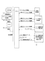
以下、本発明の実施形態に係る画像処理によるトロリ線摩耗測定装置の実施例を図1から図7を用いて説明する。図1は本発明の実施例に係る装置構成の模式図、図2は本発明の実施例に係る二値化ラインセンサ画像の図、図3は本発明の実施例に係るエッジ検出の図、図4は実施例1に係るフローチャート、図5は実施例1に係る装置構成の模式図、図6は実施例2に係る装置構成の模式図、図7は実施例3に係る装置構成の模式図、図8は実施例2に係るトロリ線の傾き補正の図、図9は実施例3に係るトロリ線の傾き補正の図、図10は本発明の実施例に係るパンタグラフ上部位置の高さを測定するフローチャート、図11は本発明の実施例に係るパンタグラフ上部位置の高さを測定する装置構成の模式図である。 Hereinafter, an example of a trolley wire wear measuring apparatus using image processing according to an embodiment of the present invention will be described with reference to FIGS. 1 is a schematic diagram of an apparatus configuration according to an embodiment of the present invention, FIG. 2 is a diagram of a binarized line sensor image according to an embodiment of the present invention, and FIG. 3 is a diagram of edge detection according to the embodiment of the present invention. 4 is a flowchart according to the first embodiment, FIG. 5 is a schematic diagram of a device configuration according to the first embodiment, FIG. 6 is a schematic diagram of a device configuration according to the second embodiment, and FIG. 7 is a schematic diagram of a device configuration according to the third embodiment. FIG. 8 is a diagram of inclination correction of the trolley line according to the second embodiment, FIG. 9 is a diagram of inclination correction of the trolley line according to the third embodiment, and FIG. 10 is the height of the upper position of the pantograph according to the embodiment of the present invention. FIG. 11 is a schematic diagram of an apparatus configuration for measuring the height of the upper position of the pantograph according to the embodiment of the present invention.
図1に示すように検査車輌10の屋根上にはラインセンサ11、ラインセンサ12、照明13、パンタグラフ14がある。本実施例による装置では、画像の取得手段としてラインセンサ11を用い、照明13には通常の白色光源を利用する。
As shown in FIG. 1, there are a
ラインセンサ11を検査車両の屋根上に鉛直上向きに設置し、ラインセンサ11の走査線の方向18が枕木方向と同じ方向になるようにし、ラインセンサ11の走査線がトロリ線16を横切るようにする。また、ラインセンサ12を検査車両の屋根上に斜め上方向きに設置し、ラインセンサ12の走査線の方向19が車両上下方向と同じ方向になるようにし、ラインセンサ12の走査線がパンタグラフ14を横切るようにする。以下に図5に示す装置構成について説明する。
The
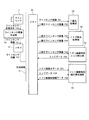
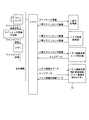
図5に示すように、ラインセンサ11で撮影して得られた走査線の画像信号F50をラインセンサ画像作成部50に送る。ラインセンサ画像作成部50では走査線の画像信号F50を時系列に並べラインセンサ画像F51を作成しメモリ51に保存する。また、走査線の画像信号F50はラインと考えることもできる。メモリ51に保存したラインセンサ画像F50は伝送線路57を介してメモリ52に保存する。
As shown in FIG. 5, an image signal F50 of a scanning line obtained by photographing with the
二値化処理部53では、メモリ52に保存したラインセンサ画像F51に二値化処理を施し、それにより得られた二値化ラインセンサ画像F52をメモリ52に保存する。
ノイズ除去処理部54では、メモリ52に保存したラインセンサ画像F52にノイズ除去処理を施し、それにより得られたノイズ除去処理済み二値化ラインセンサ画像F53をメモリ52に保存する。
The
The noise
トロリ線磨耗部エッジ検出処理部55では、メモリ52に保存したノイズ除去処理済み二値化ラインセンサ画像F53にトロリ線磨耗部エッジ検出処理を施し、それにより得られたエッジデータF54をメモリ52に保存する。
The trolley wire wear part edge
トロリ線磨耗部幅計算処理部56では、メモリ52に保存したエッジデータF54とトロリ線高さデータF55にトロリ線磨耗部幅計算処理を施し、それにより得られたトロリ線摩耗部幅データF58をメモリ52に保存する。ここで用いるトロリ線高さデータF55にはパンタグラフ上部位置高さデータF116を用いる。パンタグラフ上部位置高さデータF116は伝送線路57と伝送線路118を接続してメモリ112に保存してあるパンタグラフ上部位置高さデータF116をメモリ52に保存することで利用できるようにする(図11参照)。
In the trolley wire wear part width
以下、図4に示すトロリ線16の摩耗部の幅を測定するフローチャートを説明する。
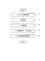
S11において、ラインセンサ11より得られる走査線(x軸)の画像信号を時系列(t軸)に並べラインセンサ画像作成部50でラインセンサ画像F51(平面の画像)を作成し、メモリ51に入力画像として保存する。
Hereinafter, a flowchart for measuring the width of the worn portion of the
In S <b> 11, the scanning line (x-axis) image signals obtained from the
S12において、ラインセンサ画像F51を伝送線路57を介してメモリ52へ保存する。ラインセンサ画像F51で帯状に撮影されたトロリ線摩耗部分とその他の背景部分を切り分けるように二値化処理を行うための閾値を設定し、二値化処理部53により閾値を用いてラインセンサ画像F51に対して二値化処理を行い、二値化ラインセンサ画像F52を得る。
In
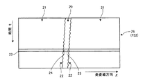
トロリ線16の摩耗部分はトロリ線16がパンタグラフ14により削られた部分であるため、摩耗していない部分に比べて強い光沢がある、このためラインセンサ画像F51上においてもトロリ線16の摩耗部分は背景部分と比較して輝度値の異なる帯状の部分として撮影されている。この処理により図2に示すような二値化ラインセンサ画像F52が得られる。二値化ラインセンサ画像26上ではトロリ線摩耗部分が白20、背景部分が黒21で表される。
The worn portion of the
S13において、ラインセンサ画像F52に二値化処理を施して得られた二値化ラインセンサ画像F52に対し、ノイズ除去処理部54により膨張処理および収縮処理を行うことでノイズを除去する。この処理をノイズ除去処理という。これはラインセンサ画像F51に二値化処理を施すことにより得られる二値化ラインセンサ画像F52にはトロリ線16の摩耗部の傷や背景部分の状態により細かな点々状のノイズが含まれる場合があるためである。
In S13, noise is removed by performing expansion processing and contraction processing by the noise
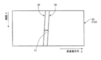
S14において、ノイズ除去後の二値化ラインセンサ画像F53上においてトロリ線摩耗部エッジ検出部55により白20で表されているトロリ線13の摩耗部分の両側のエッジ22を検出する。この処理をトロリ線磨耗部エッジ検出処理という。これらのエッジは、二値化ラインセンサ画像のあるライン23について左から探索した場合、背景の黒21から摩耗部分の白20へ変化する点(以下、アップエッジ)が摩耗部分左側のエッジ24として、また摩耗部分の白20から背景の黒21へ変化する点(以下、ダウンエッジ)を摩耗部分右側のエッジ点25として検出することができる。この処理を画像の上から下へ各ラインごとに行うことで、図3に示すように1枚の二値化ラインセンサ画像F53に関するトロリ線の磨耗部分のエッジ30を検出することができる。
In S14, the
S15において、二値化ラインセンサ画像F53から検出したトロリ線摩耗部分の両側のエッジデータF54を用いて、ラインセンサの一つの走査線上にある両側のエッジ間距離31をトロリ線摩耗部分の画像上の幅として計算する。この処理をトロリ線磨耗部幅計算処理という。
In S15, using the edge data F54 on both sides of the trolley line wear portion detected from the binarized line sensor image F53, the
この時のラインセンサ11からトロリ線16までの高さ、レンズ焦点距離、センサ幅、センサ画素数から1画素[pix]に対する実寸法[mm]の度合いである画像分解能[mm/pix]を計算し、トロリ線摩耗部分の画像上の幅と画像分解能の乗算を行うことでトロリ線摩耗部分の幅を計算する。求めたエッジデータ、トロリ線摩耗部幅、計算に用いたラインセンサ画像や対応する走査線を指し示すデータ等は記録部(図示せず)に記録しておく。
At this time, the image resolution [mm / pix] that is the degree of the actual dimension [mm] with respect to one pixel [pix] is calculated from the height from the
ここで、計算に用いるラインセンサ11からトロリ線16までの高さF55については、パンタグラフ上部位置15の高さを測定して、そのパンタグラフ上部位置15の高さをラインセンサ11からトロリ線16までの高さとすることで、S15でのトロリ線摩耗部分の幅の計算に用いる。このパンタグラフ上部位置15の高さは伝送線路57を通してメモリ52に保存する。
Here, for the height F55 from the
パンタグラフ14の高さを測定するためにラインセンサ12を設け、ラインセンサ12の走査線の方向がパンタグラフ14の下から上へ向かう方向となるように、パンタグラフ14の前方にラインセンサ12を設置する。
A
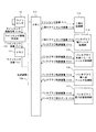
以下に図11に示すパンタグラフの高さ測定装置の構成について説明する。ラインセンサ12で撮影して得られた走査線の画像信号F110はラインセンサ画像作成部110に送られる。ラインセンサ画像作成部110では走査線の画像信号F110を時系列に並べラインセンサ画像F111を作成しメモリ111に保存する。メモリ111に保存したラインセンサ画像F111は伝送線路118を介してメモリ112に保存する。
The configuration of the pantograph height measuring apparatus shown in FIG. 11 will be described below. An image signal F110 of the scanning line obtained by photographing with the
二値化処理部113ではメモリ112に保存したラインセンサ画像F111に二値化処理を施し、それにより得られた二値化ラインセンサ画像F112をメモリ112に保存する。
パンタグラフ幅フィルタ処理部114ではメモリ112に保存した二値化ラインセンサ画像F112にパンタグラフ幅フィルタ処理を施し、得られたパンタグラフ幅フィルタ処理済みパンタグラフ軌跡画像F113をメモリ112に保存する。
The
The pantograph width
パンタグラフ軌跡トレースフィルタ処理部115ではメモリ112に保存したパンタグラフ幅フィルタ処理済みパンタグラフ軌跡画像F113にパンタグラフ軌跡トレースフィルタ処理を施し、得られたパンタグラフ軌跡トレースフィルタ処理済みパンタグラフ軌跡画像F114をメモリ112に保存する。
The pantograph trajectory trace
パンタグラフ単一点フィルタ処理部116ではメモリ112に保存したパンタグラフ軌跡トレースフィルタ処理済みパンタグラフ軌跡画像F114にパンタグラフ単一点フィルタ処理を施し、得られたパンタグラフ単一点フィルタ処理済みパンタグラフ軌跡画像F115をメモリ112に保存する。
The pantograph single-point
パンタグラフ上部位置高さ計算処理部117ではメモリ112に保存したパンタグラフ単一点フィルタ処理済みパンタグラフ軌跡画像F115にパンタグラフ上部位置高さ計算処理を施し、得られたパンタグラフ上部位置高さデータF116をメモリ112に保存する。
The pantograph upper position height
以下に図10に示すパンタグラフ上部位置高さ測定方法のフローチャートについて説明する。
S21において、ラインセンサ12より得られる走査線(y軸)の画像信号を時系列(t軸)に並べラインセンサ画像作成部110でラインセンサ画像F111(平面の画像)を作成し、メモリ111に入力画像として保存する。
Hereinafter, a flowchart of the pantograph upper position height measuring method shown in FIG. 10 will be described.
In S <b> 21, the scanning line (y-axis) image signals obtained from the
S22において、ラインセンサ画像F111に二値化処理を施す。ラインセンサ12でパンタグラフ14を撮影した場合、既存の構造物17がパンタグラフ14と同様にラインセンサ画像F111に撮影されている。このため、パンタグラフ14と既存の構造物17とを切り分ける必要がある。
In S22, the binarization process is performed on the line sensor image F111. When the
ラインセンサ画像F111上において、パンタグラフ14部分は背景部分と比較して輝度値の異なる帯状の部分として撮影される。そこで帯状に撮影されたパンタグラフ14部分とその他の背景部分を切り分けるように閾値を設定し、その閾値を用いてラインセンサ画像F111に二値化処理を行う。このとき、パンタグラフ14部分が白、背景部分が黒となるように二値化ラインセンサ画像F112を構成する。
On the line sensor image F111, the
このときパンタグラフ14部分がパンタグラフ14の厚みに対応したある一定の幅を持った帯として二値化ラインセンサ画像F112上に現れることに注目し、二値化ラインセンサ画像F112上においてパンタグラフ14の幅と同じ幅を持つ白い部分を検出することでパンタグラフ14部分を検出する。
At this time, it is noted that the
S23において、パンタグラフ幅フィルタ処理を行う。二値化ラインセンサ画像F112の1つの走査線に対して走査方向に検査し、アップエッジとダウンエッジを検出する。 In S23, pantograph width filter processing is performed. One scanning line of the binarized line sensor image F112 is inspected in the scanning direction, and an up edge and a down edge are detected.
1つの走査線上にあるアップエッジとダウンエッジの間隔が設定しておいた幅の範囲に入る部分をパンタグラフ14部分として検出し、そのときのダウンエッジをパンタグラフ上部位置として白で残し、他の部分を黒とする処理を行ってパンタグラフ上部位置15の軌跡を求める。この処理をパンタグラフ幅フィルタ処理という。また、このとき作成されるパンタグラフ上部位置の軌跡を表す画像をパンタグラフ軌跡画像F113という。
The part where the interval between the up edge and the down edge on one scanning line falls within the set width is detected as the
しかし、このパンタグラフ幅フィルタ処理によってパンタグラフ上部位置15の軌跡を求めた場合、いくつかの部分でパンタグラフ上部位置15でない部分が検出される場合がある。これはトロリ線16、碍子、トロリ線吊り上げ用ワイヤ類といったパンタグラフ14以外の物体が二値化ラインセンサ画像F112上でパンタグラフ14の幅に近い状態になった場合に発生する。これは、パンタグラフ軌跡画像F113中にノイズとして残るため、これらを消去する必要がある。
However, when the trajectory of the pantograph
S24において、パンタグラフ軌跡トレースフィルタ処理を行う。パンタグラフ14は二値化ラインセンサ画像F112上に一定の幅で継続して存在するため、このパンタグラフ14はパンタグラフ軌跡画像F113ではパンタグラフ上部位置15の点が連続した曲線として存在することに注目し、設定した長さより短い点列はノイズとして消去する。この処理をパンタグラフ軌跡トレースフィルタ処理という。
In S24, a pantograph trajectory trace filter process is performed. Since the
しかし、このパンタグラフ軌跡トレースフィルタ処理によるノイズ消去では、連続しない短い点列となるノイズ部分を削除することはできるが、パンタグラフ上部位置の軌跡と判断するように設定してある長さを満たすノイズ部分については消去することができない。 However, with noise elimination by this pantograph trajectory trace filter processing, it is possible to delete the noise part that becomes a short continuous dot sequence, but the noise part that satisfies the length set to be judged as the trajectory of the upper position of the pantograph Cannot be erased.
パンタグラフ軌跡トレースフィルタ処理とは別のノイズ消去方法として、パンタグラフがラインセンサ画像上で一つのみであるためラインセンサの走査線上においてパンタグラフ上部位置が一点のみであり、また、パンタグラフ幅フィルタ処理によって検出された点はパンタグラフ軌跡画像ではパンタグラフ上部位置の点がほとんどであることに注目する。 As a noise elimination method different from the pantograph trajectory trace filter processing, since there is only one pantograph on the line sensor image, the top position of the pantograph is only one point on the scanning line of the line sensor, and it is detected by pantograph width filter processing. It is noted that most of the pantograph trajectory images are points at the upper position of the pantograph.
S25において、パンタグラフ単一点フィルタ処理を行う。パンタグラフ軌跡画像の点についてラインセンサ走査線方向の1ラインに関して軌跡点が複数存在する場合は軌跡店の平均位置に最も近い点をパンタグラフ上部位置の点としてその他を消去する。この処理をパンタグラフ単一点フィルタ処理という。 In S25, a pantograph single point filter process is performed. When there are a plurality of trajectory points for one line in the line sensor scanning line direction with respect to the points of the pantograph trajectory image, the points closest to the average position of the trajectory store are taken as points at the upper position of the pantograph and the others are deleted. This process is called pantograph single point filter process.
S26において、パンタグラフ上部位置高さ計算処理を行う。ノイズを除去したパンタグラフ軌跡画像を変換しパンタグラフの上部の実際の三次元高さを求める。この変換にはラインセンサの設置位置姿勢データから得られる射影変換を用いる。 In S26, a pantograph upper position height calculation process is performed. The pantograph trajectory image from which noise is removed is converted to obtain the actual three-dimensional height at the top of the pantograph. For this conversion, projective conversion obtained from the installation position and orientation data of the line sensor is used.
このようにして求めたパンタグラフ上部位置高さを、伝送線路118(図11参照)と伝送線路57(図5参照)とを接続し、トロリ線摩耗部幅計算処理部56でトロリ線高さデータF55として利用する。
The pantograph upper position height obtained in this way is connected to the transmission line 118 (see FIG. 11) and the transmission line 57 (see FIG. 5), and the trolley line wear part width
また、トロリ線の高さは架線の保守及び点検等を行うときに必要なため、あらかじめ測定してある場合もあるので、このあらかじめ測定してある値をトロリ線高さデータF55として利用することもできる。 In addition, since the height of the trolley wire is necessary for maintenance and inspection of the overhead wire, it may be measured in advance, so the value measured in advance should be used as the trolley wire height data F55. You can also.
図6に示す本発明による装置では、実施例1に示した装置でトロリ線摩耗部幅の計算処理S15(図4参照)を行う際にトロリ線摩耗部計算処理部60において、トロリ線傾き補正付きトロリ線摩耗部計算処理を行う。
In the apparatus according to the present invention shown in FIG. 6, when the trolley wire wear part width calculation process S15 (see FIG. 4) is performed by the apparatus shown in the first embodiment, the trolley wire wear part
図8に示すように計算対象となっているライン87上の左側のエッジ点80について、近傍の設定した範囲81内のエッジ点を直線82で直線近似し、その直線82に垂直に交わり、計測対象となっているエッジ点80を通る直線83ともう一方のエッジ点85との交点を検出し、計算対象となっているエッジ点80と検出したエッジ交点85との距離86をそのエッジ点80におけるトロリ線摩耗部幅として求める。
As shown in FIG. 8, with respect to the
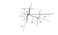
図7に示す本発明による装置では、実施例2に示した装置でトロリ線摩耗部幅の計算処理S15(図4参照)を行う際にトロリ線摩耗部計算処理部70において、トロリ線傾き補正付きトロリ線摩耗部罫線処理を行う。
In the apparatus according to the present invention shown in FIG. 7, when the trolley wire wear part width calculation process S15 (see FIG. 4) is performed by the apparatus shown in the second embodiment, the trolley wire wear part
図9に示すように計測対象となっているライン102上の左側のエッジ点90および右側のエッジ点91について、それら近傍の設定した範囲92内のエッジ点を直線93,94で直接近似し、直線近似した際の近似誤差95,96の総計がより小さい方のエッジ点93もしくはエッジ点94を計測基準点とし、計測基準点を通り直線93もしくは直線94に垂直に交わる直線98もしくは直線101ともう一方のエッジとの交点を求め、計測基準点と検出したエッジ交点との距離をその点におけるトロリ線摩耗部幅として求める。
As shown in FIG. 9, for the
例として左側のエッジ90の誤差の総計が右側のエッジ91よりも小さいとした場合、計測基準点97を通り近似直線93に垂直な傾きを持つ直線98ともう一方のエッジとの交点99を求め、計測基準点97と検出したエッジ交点99との距離100をその点におけるトロリ線摩耗部幅として求める。
For example, when the total error of the
本発明に係る画像処理によるトロリ線摩耗測定装置は、電気鉄道へ電力を供給するためのトロリ線の摩耗測定に用いることができる。 The trolley wire wear measuring apparatus using image processing according to the present invention can be used for measuring trolley wire wear for supplying electric power to an electric railway.
11 ラインセンサ
16 トロリ線
26 二値化ラインセンサ画像
32 エッジ検出
80、97 左側のエッジ点
102 右側のエッジ点
82、93、94 近似直線
83、98、101 近似直線に垂直な傾きを持つ直線
85、99 エッジ交点
23、87、102 ライン
11
Claims (2)
ラインセンサ画像に対して二値化処理を行うことによりトロリ線摩耗部分を強調した二値化ラインセンサ画像とする二値化処理手段と、
前記二値化ラインセンサ画像のノイズを除去するノイズ除去処理手段と、
ノイズ除去後の前記二値化ラインセンサ画像からトロリ線摩耗部のエッジを検出しエッジデータとするエッジ検出処理手段と、
前記エッジデータとラインセンサを基準としたときのトロリ線の高さのデータであるトロリ線高さデータに基づいてトロリ線摩耗部幅の計算を行うトロリ線摩耗部幅計算処理手段と
を有し、
前記トロリ線摩耗部幅計算処理手段に、
計算対象となっているライン上の1つのエッジ点を基準エッジ点とし、前記基準エッジ点の近傍に設定した範囲内にあるエッジ点の近似直線を求め、
その近似直線に垂直で、かつ、前記基準エッジ点を通る垂直直線を求め、
前記垂直直線と前記基準エッジ点があるエッジと対をなす方のエッジとの交点を検出してエッジ交点とし、前記基準エッジ点と前記エッジ交点との距離を前記基準エッジ点におけるトロリ線摩耗部幅として求める処理を加えた
ことを特徴とする画像処理によるトロリ線摩耗測定装置。 Line sensor image creating means for creating a line sensor image using a line sensor;
Binarization processing means to binarize the line sensor image by emphasizing the trolley wire wear part by performing binarization processing on the line sensor image;
Noise removal processing means for removing noise from the binarized line sensor image;
Edge detection processing means for detecting the edge of the trolley wire wear part from the binarized line sensor image after noise removal and using it as edge data;
Possess a trolley wire worn portion width calculation processing means for calculating the trolley wire worn portion width based on the trolley wire height data is the height of the data of the trolley wire when based on the said edge data and the line sensor ,
In the trolley wire wear part width calculation processing means,
Using one edge point on the calculation target line as a reference edge point, an approximate straight line of the edge point within the range set in the vicinity of the reference edge point is obtained,
A vertical straight line that is perpendicular to the approximate straight line and passes through the reference edge point is obtained,
An intersection of the vertical straight line and the edge that forms a pair with the reference edge point is detected as an edge intersection, and the distance between the reference edge point and the edge intersection is a trolley wire wear portion at the reference edge point An apparatus for measuring trolley wire wear by image processing, characterized in that processing for obtaining width is added .
ラインセンサ画像に対して二値化処理を行うことによりトロリ線摩耗部分を強調した二値化ラインセンサ画像とする二値化処理手段と、
前記二値化ラインセンサ画像のノイズを除去するノイズ除去処理手段と、
ノイズ除去後の前記二値化ラインセンサ画像からトロリ線摩耗部のエッジを検出しエッジデータとするエッジ検出処理手段と、
前記エッジデータとラインセンサを基準としたときのトロリ線の高さのデータであるトロリ線高さデータに基づいてトロリ線摩耗部幅の計算を行うトロリ線摩耗部幅計算処理手段と
を有し、
前記トロリ線摩耗部幅計算処理手段に、
計測対象となっているライン上の2つのエッジ点を各々基準エッジ点とし、前記2つの基準エッジ点の近傍に設定した範囲内にあるエッジ点の近似直線を各々求め、この近似直線と前記設定した範囲内にあるエッジ点との誤差の総和を求め、
前記誤差の総和の小さい方の基準エッジ点の近似直線に垂直で、かつ、計測対象となっている前記基準エッジ点を通る垂直直線を求め、
前記垂直直線と基準エッジ点があるエッジと対をなす方のエッジとの交点を検出してエッジ交点とし、前記誤差の総和の小さい方の基準エッジ点と前記エッジ交点との距離を前記誤差の総和の小さい方の基準エッジ点におけるトロリ線摩耗部幅として求める処理を加えた
ことを特徴とする画像処理によるトロリ線摩耗測定装置。 Line sensor image creating means for creating a line sensor image using a line sensor;
Binarization processing means to binarize the line sensor image by emphasizing the trolley wire wear part by performing binarization processing on the line sensor image;
Noise removal processing means for removing noise from the binarized line sensor image;
Edge detection processing means for detecting the edge of the trolley wire wear part from the binarized line sensor image after noise removal and using it as edge data;
A trolley wire wear portion width calculation processing means for calculating a trolley wire wear portion width based on the trolley wire height data, which is trolley wire height data when the edge data and the line sensor are used as a reference;
Have
In the trolley wire wear part width calculation processing means,
Two edge points on the measurement target line are set as reference edge points, respectively, and approximate lines of edge points within a range set in the vicinity of the two reference edge points are obtained, and the approximate line and the set value are obtained. Find the sum of the errors with the edge points in the range
Obtain a vertical straight line that is perpendicular to the approximate straight line of the reference edge point with the smaller sum of errors and that passes through the reference edge point being measured,
The intersection of the vertical straight line and the edge that is paired with the edge with the reference edge point is detected as an edge intersection, and the distance between the reference edge point with the smaller sum of the errors and the edge intersection is calculated as the error. A trolley wire wear measuring apparatus using image processing, characterized in that a process for obtaining a trolley wire wear part width at a reference edge point having a smaller sum is added.
Priority Applications (4)
| Application Number | Priority Date | Filing Date | Title |
|---|---|---|---|
| JP2005068796A JP4635657B2 (en) | 2005-03-11 | 2005-03-11 | Trolley wire wear measuring device by image processing |
| TW095108060A TWI306814B (en) | 2005-03-11 | 2006-03-10 | Image-processing based trolley wire wear measurement apparatus,image-processing based trolley wire wear measurement method and image-processing based trolley wire wear inspector vehicle |
| FR0650819A FR2882973B1 (en) | 2005-03-11 | 2006-03-10 | APPARATUS FOR MEASURING THE WEAR OF AN AIR WIRE EFFECTED ON THE BASIS OF IMAGE PROCESSING |
| CNB2006100547822A CN100494882C (en) | 2005-03-11 | 2006-03-10 | Image processing-based wear measurement device for trolley wires |
Applications Claiming Priority (1)
| Application Number | Priority Date | Filing Date | Title |
|---|---|---|---|
| JP2005068796A JP4635657B2 (en) | 2005-03-11 | 2005-03-11 | Trolley wire wear measuring device by image processing |
Publications (2)
| Publication Number | Publication Date |
|---|---|
| JP2006248411A JP2006248411A (en) | 2006-09-21 |
| JP4635657B2 true JP4635657B2 (en) | 2011-02-23 |
Family
ID=36928530
Family Applications (1)
| Application Number | Title | Priority Date | Filing Date |
|---|---|---|---|
| JP2005068796A Expired - Fee Related JP4635657B2 (en) | 2005-03-11 | 2005-03-11 | Trolley wire wear measuring device by image processing |
Country Status (4)
| Country | Link |
|---|---|
| JP (1) | JP4635657B2 (en) |
| CN (1) | CN100494882C (en) |
| FR (1) | FR2882973B1 (en) |
| TW (1) | TWI306814B (en) |
Cited By (5)
| Publication number | Priority date | Publication date | Assignee | Title |
|---|---|---|---|---|
| CN106601642A (en) * | 2015-10-15 | 2017-04-26 | 三星电子株式会社 | Method of measuring thickness, method of processing image and electronic system performing the same |
| TWI593939B (en) * | 2015-01-30 | 2017-08-01 | Meidensha Electric Mfg Co Ltd | Overhead wire abrasion measuring apparatus and overhead wire abrasion measuring method |
| WO2020129368A1 (en) * | 2018-12-19 | 2020-06-25 | 株式会社明電舎 | Wear measurement device and wear measurement method |
| US10864825B2 (en) | 2016-02-22 | 2020-12-15 | Mitsubishi Heavy Industries Engineering, Ltd. | Wear degree information acquiring device, wear degree information acquiring method, vehicle and program |
| JP2023138303A (en) * | 2022-03-17 | 2023-10-02 | 株式会社明電舎 | Pantograph acceleration measuring device and measuring method |
Families Citing this family (32)
| Publication number | Priority date | Publication date | Assignee | Title |
|---|---|---|---|---|
| JP2007271446A (en) | 2006-03-31 | 2007-10-18 | Meidensha Corp | Instrument for measuring abrasion in trolley wire by imaging processing |
| JP4973108B2 (en) * | 2006-10-05 | 2012-07-11 | 株式会社明電舎 | Trolley wire wear measuring device |
| JP5162874B2 (en) * | 2006-10-05 | 2013-03-13 | 株式会社明電舎 | Trolley wire wear measuring device |
| JP4816567B2 (en) * | 2007-05-25 | 2011-11-16 | 株式会社明電舎 | Trolley wire wear measuring device by image processing |
| JP4858316B2 (en) * | 2007-06-04 | 2012-01-18 | 株式会社明電舎 | Trolley wire wear measuring device by image processing |
| JP5228438B2 (en) * | 2007-10-22 | 2013-07-03 | 株式会社明電舎 | Trolley wire wear amount measuring device |
| JP5245445B2 (en) * | 2008-02-15 | 2013-07-24 | 株式会社明電舎 | Crossover measuring device |
| JP5223472B2 (en) * | 2008-06-06 | 2013-06-26 | 株式会社明電舎 | Wear measuring apparatus and wear measuring method |
| JP5151845B2 (en) * | 2008-09-17 | 2013-02-27 | 株式会社明電舎 | Apparatus and method for measuring vertical acceleration of pantograph by image processing |
| JP5287177B2 (en) * | 2008-11-27 | 2013-09-11 | 株式会社明電舎 | Trolley wire wear and displacement measuring device by image processing |
| JP5418176B2 (en) * | 2009-01-22 | 2014-02-19 | 株式会社明電舎 | Pantograph height measuring device and calibration method thereof |
| DE102009018763B4 (en) * | 2009-04-27 | 2011-10-06 | Db Netz Ag | Method for detecting components in overhead line installations of rail vehicles, in particular railway vehicles |
| JP5321235B2 (en) * | 2009-05-15 | 2013-10-23 | 株式会社明電舎 | Pantograph displacement measuring device and trolley wire hard spot detection method |
| CN101718530B (en) * | 2009-11-18 | 2011-05-18 | 上海理工大学 | On-line detection system of electromagnetic wire lapping |
| JP5423567B2 (en) * | 2010-04-30 | 2014-02-19 | 株式会社明電舎 | Vehicle position measuring device for electric railway maintenance |
| JP5736853B2 (en) * | 2011-03-08 | 2015-06-17 | 株式会社明電舎 | Trolley wire wear condition monitoring device |
| CN102507600B (en) * | 2011-11-08 | 2013-06-05 | 南京大学 | Automatic detection device for wear of pantograph slide plate of high-speed locomotive |
| WO2014024812A1 (en) * | 2012-08-06 | 2014-02-13 | 株式会社 明電舎 | Support detection device using laser measurement |
| JP5656958B2 (en) * | 2012-11-06 | 2015-01-21 | 株式会社アドバンテスト | Pattern inspection method and pattern inspection apparatus |
| FR3001416B1 (en) * | 2013-01-29 | 2015-02-27 | Sncf | DEVICE FOR DETECTING THE WEAR OF A CATENARY CONTACT WIRE |
| JP5534058B1 (en) * | 2013-02-19 | 2014-06-25 | 株式会社明電舎 | Wear measuring apparatus and method |
| JP6069701B2 (en) * | 2013-02-19 | 2017-02-01 | 株式会社明電舎 | Wear measuring apparatus and method |
| CN103776383B (en) * | 2014-01-17 | 2016-06-08 | 太原理工大学 | A kind of mining belt conveyer support roller online non-contact detection method of outer tube wear intensity |
| JP6347069B2 (en) * | 2014-05-30 | 2018-06-27 | 株式会社明電舎 | Apparatus and method for measuring trolley wire wear by image processing |
| JP6427797B2 (en) * | 2015-03-13 | 2018-11-28 | 株式会社明電舎 | Hanger detection device by image processing |
| JP6484855B2 (en) * | 2015-04-21 | 2019-03-20 | 株式会社明電舎 | Trolley wire wear estimation method and apparatus |
| JP6518940B2 (en) * | 2015-06-23 | 2019-05-29 | 株式会社明電舎 | Filament measurement apparatus and method |
| CN105620294B (en) * | 2016-03-21 | 2018-02-02 | 北京科技大学 | A kind of trackless electric car of public traffic is intelligently made contact method and device |
| CN109211120B (en) * | 2018-09-25 | 2019-10-08 | 北京华开领航科技有限责任公司 | Contact line Abrasion detecting device |
| JP6669294B1 (en) | 2019-03-07 | 2020-03-18 | 株式会社明電舎 | Pantograph displacement measuring device and trolley wire hard point detection method |
| CN116804597B (en) * | 2023-08-22 | 2023-12-15 | 梁山华鲁专用汽车制造有限公司 | Trailer connection state detection device and detection method |
| DE102023211983A1 (en) * | 2023-11-30 | 2025-06-05 | Siemens Mobility GmbH | Monitoring wear of a contact strip |
Family Cites Families (6)
| Publication number | Priority date | Publication date | Assignee | Title |
|---|---|---|---|---|
| JPH04260838A (en) * | 1991-02-15 | 1992-09-16 | Toshiba Corp | Electric overhead line abrasion detecting device |
| JPH0596980A (en) * | 1991-10-09 | 1993-04-20 | Mitsubishi Heavy Ind Ltd | Overhead wire inspecting device |
| JPH05124461A (en) * | 1991-11-05 | 1993-05-21 | Toshiba Corp | Wear processing device for electric overhead line |
| JP3553168B2 (en) * | 1994-12-14 | 2004-08-11 | 東海旅客鉄道株式会社 | Image display method of trolley line sliding surface |
| JP3629568B2 (en) * | 1995-10-26 | 2005-03-16 | 川崎重工業株式会社 | Overhead wire inspection method and overhead wire inspection apparatus |
| ITVE20000036A1 (en) * | 2000-07-18 | 2002-01-18 | Tecnogamma S A S Di Zanini E & | DETECTION EQUIPMENT OF THE CHARACTERISTIC PARAMETERS OF A RAILWAY AERIAL LINE. |
-
2005
- 2005-03-11 JP JP2005068796A patent/JP4635657B2/en not_active Expired - Fee Related
-
2006
- 2006-03-10 CN CNB2006100547822A patent/CN100494882C/en not_active Expired - Fee Related
- 2006-03-10 TW TW095108060A patent/TWI306814B/en active
- 2006-03-10 FR FR0650819A patent/FR2882973B1/en not_active Expired - Lifetime
Cited By (7)
| Publication number | Priority date | Publication date | Assignee | Title |
|---|---|---|---|---|
| TWI593939B (en) * | 2015-01-30 | 2017-08-01 | Meidensha Electric Mfg Co Ltd | Overhead wire abrasion measuring apparatus and overhead wire abrasion measuring method |
| CN106601642A (en) * | 2015-10-15 | 2017-04-26 | 三星电子株式会社 | Method of measuring thickness, method of processing image and electronic system performing the same |
| CN106601642B (en) * | 2015-10-15 | 2021-07-09 | 三星电子株式会社 | Method for measuring thickness, method for processing images and electronic system for performing the same |
| US10864825B2 (en) | 2016-02-22 | 2020-12-15 | Mitsubishi Heavy Industries Engineering, Ltd. | Wear degree information acquiring device, wear degree information acquiring method, vehicle and program |
| WO2020129368A1 (en) * | 2018-12-19 | 2020-06-25 | 株式会社明電舎 | Wear measurement device and wear measurement method |
| JP2020098533A (en) * | 2018-12-19 | 2020-06-25 | 株式会社明電舎 | Abrasion measuring apparatus and abrasion measuring method |
| JP2023138303A (en) * | 2022-03-17 | 2023-10-02 | 株式会社明電舎 | Pantograph acceleration measuring device and measuring method |
Also Published As
| Publication number | Publication date |
|---|---|
| TW200708424A (en) | 2007-03-01 |
| CN1837746A (en) | 2006-09-27 |
| FR2882973B1 (en) | 2015-05-01 |
| TWI306814B (en) | 2009-03-01 |
| CN100494882C (en) | 2009-06-03 |
| JP2006248411A (en) | 2006-09-21 |
| FR2882973A1 (en) | 2006-09-15 |
Similar Documents
| Publication | Publication Date | Title |
|---|---|---|
| JP4635657B2 (en) | Trolley wire wear measuring device by image processing | |
| KR101214645B1 (en) | Trolley wire wear measuring device | |
| KR101280243B1 (en) | Measuring system for height and stagger and wear of catenary using machine vision | |
| CN105393080B (en) | Overhead line measurement device and overhead line assay method | |
| EP3252428B1 (en) | Overhead wire wear measurement device and overhead wire wear measurement method | |
| EP2960620B1 (en) | Wear measuring device and method for same | |
| JP5287177B2 (en) | Trolley wire wear and displacement measuring device by image processing | |
| RU2430331C2 (en) | Device to measure contact aerial wear by image processing | |
| JP5223472B2 (en) | Wear measuring apparatus and wear measuring method | |
| JP5162874B2 (en) | Trolley wire wear measuring device | |
| JP4858316B2 (en) | Trolley wire wear measuring device by image processing | |
| JP4779770B2 (en) | Trolley wire wear measuring device by image processing | |
| KR20100020671A (en) | Equipment to measure thickness and distinguish shape of steel materials using vision camera, and method to measure thickness and distinguish shape of steel materials using the same | |
| JP7264001B2 (en) | Wear detection device | |
| JP6268382B2 (en) | Trolley wire wear measuring apparatus and trolley wire wear measuring method by image processing | |
| JP4797568B2 (en) | Slab vertical crack detection method and apparatus |
Legal Events
| Date | Code | Title | Description |
|---|---|---|---|
| A621 | Written request for application examination |
Free format text: JAPANESE INTERMEDIATE CODE: A621 Effective date: 20071220 |
|
| A131 | Notification of reasons for refusal |
Free format text: JAPANESE INTERMEDIATE CODE: A131 Effective date: 20100720 |
|
| A521 | Request for written amendment filed |
Free format text: JAPANESE INTERMEDIATE CODE: A523 Effective date: 20100909 |
|
| TRDD | Decision of grant or rejection written | ||
| A01 | Written decision to grant a patent or to grant a registration (utility model) |
Free format text: JAPANESE INTERMEDIATE CODE: A01 Effective date: 20101026 |
|
| A01 | Written decision to grant a patent or to grant a registration (utility model) |
Free format text: JAPANESE INTERMEDIATE CODE: A01 |
|
| A61 | First payment of annual fees (during grant procedure) |
Free format text: JAPANESE INTERMEDIATE CODE: A61 Effective date: 20101108 |
|
| FPAY | Renewal fee payment (event date is renewal date of database) |
Free format text: PAYMENT UNTIL: 20131203 Year of fee payment: 3 |
|
| R150 | Certificate of patent or registration of utility model |
Ref document number: 4635657 Country of ref document: JP Free format text: JAPANESE INTERMEDIATE CODE: R150 Free format text: JAPANESE INTERMEDIATE CODE: R150 |
|
| LAPS | Cancellation because of no payment of annual fees |