US8071952B2 - Radiographic image detection device - Google Patents
Radiographic image detection device Download PDFInfo
- Publication number
- US8071952B2 US8071952B2 US12/539,628 US53962809A US8071952B2 US 8071952 B2 US8071952 B2 US 8071952B2 US 53962809 A US53962809 A US 53962809A US 8071952 B2 US8071952 B2 US 8071952B2
- Authority
- US
- United States
- Prior art keywords
- radiation
- handle
- radiographic image
- section
- attachment portions
- Prior art date
- Legal status (The legal status is an assumption and is not a legal conclusion. Google has not performed a legal analysis and makes no representation as to the accuracy of the status listed.)
- Active, expires
Links
- 238000001514 detection method Methods 0.000 title claims abstract description 58
- 230000005855 radiation Effects 0.000 claims abstract description 99
- 238000003384 imaging method Methods 0.000 claims abstract description 60
- 238000009423 ventilation Methods 0.000 claims description 7
- 230000001186 cumulative effect Effects 0.000 description 6
- 230000006870 function Effects 0.000 description 5
- 239000011159 matrix material Substances 0.000 description 5
- 230000000694 effects Effects 0.000 description 4
- 239000000758 substrate Substances 0.000 description 4
- 230000000717 retained effect Effects 0.000 description 3
- BUGBHKTXTAQXES-UHFFFAOYSA-N Selenium Chemical compound [Se] BUGBHKTXTAQXES-UHFFFAOYSA-N 0.000 description 2
- 239000000470 constituent Substances 0.000 description 2
- 238000000034 method Methods 0.000 description 2
- 230000000644 propagated effect Effects 0.000 description 2
- 229910052711 selenium Inorganic materials 0.000 description 2
- 239000011669 selenium Substances 0.000 description 2
- 230000005540 biological transmission Effects 0.000 description 1
- 238000010586 diagram Methods 0.000 description 1
- 239000000463 material Substances 0.000 description 1
- 238000007747 plating Methods 0.000 description 1
- 230000033764 rhythmic process Effects 0.000 description 1
- 239000010409 thin film Substances 0.000 description 1
- 230000001131 transforming effect Effects 0.000 description 1
Images


Classifications
-
- G—PHYSICS
- G03—PHOTOGRAPHY; CINEMATOGRAPHY; ANALOGOUS TECHNIQUES USING WAVES OTHER THAN OPTICAL WAVES; ELECTROGRAPHY; HOLOGRAPHY
- G03B—APPARATUS OR ARRANGEMENTS FOR TAKING PHOTOGRAPHS OR FOR PROJECTING OR VIEWING THEM; APPARATUS OR ARRANGEMENTS EMPLOYING ANALOGOUS TECHNIQUES USING WAVES OTHER THAN OPTICAL WAVES; ACCESSORIES THEREFOR
- G03B42/00—Obtaining records using waves other than optical waves; Visualisation of such records by using optical means
- G03B42/02—Obtaining records using waves other than optical waves; Visualisation of such records by using optical means using X-rays
- G03B42/04—Holders for X-ray films
Definitions
- the present invention relates to a radiographic image detection device, and more particularly to a radiographic image detection device that features portability.
- FPDs flat panel detectors
- TFT thin film transistor
- X-rays can be directly converted to digital data.
- portable radiographic image detection devices (below referred to as electronic cassettes) have been realized in which image data, which represents a radiographic image that is expressed by radiation passing through a subject and being irradiated, is generated and the generated image data is stored.
- a handle which functions as a carrying handle, is often provided at this kind of electronic cassette.
- the electronic cassette In a radiographic image detection system that utilizes an electronic cassette, the electronic cassette is disposed to be spaced apart from a radiation generation section that generates radiation such as or the like. At a time of capturing of a radiographic image, a subject of imaging is disposed between the radiation generation section and the electronic cassette. If a condition of imaging is a standing position, the electronic cassette is mounted on a standing position frame, and if the imaging condition is a recumbent position, the electronic cassette is inserted between a bed and the subject of imaging. In either of these imaging conditions, the standing position or the recumbent position, it is necessary that the handle provided at the electronic cassette does not become an impediment to imaging.
- the carrying handle may be an impediment when the electronic cassette is being mounted in a standing position frame or when the electronic cassette is being inserted between a bed and a subject of imaging, or the like.
- the present invention has been made in order to solve the problem described above, and an object is to provide a radiographic image detection device capable of facilitating handling in orientations corresponding to imaging conditions, without impairing portability.
- the present invention provides a radiographic image detection device including:
- a handle is attachable
- the radiation detection portion detecting radiation that has passed through a subject of imaging and been irradiated through the irradiation surface, and outputting image information that represents a radiographic image in accordance with detected radiation amounts;
- a handle portion that is attachable and detachable at the attachment portions.
- the attachment portions to which a handle can be attached are provided at plural locations in side faces of the radiation detection portion, which detects radiation irradiated through the irradiation surface at which radiation is irradiated through a subject of imaging and which outputs image information that represents a radiographic image in accordance with detected radiation amounts, and the handle portion is attachable/detachable with respect to the attachment portions.
- the attachment portions to which the handle portion is attachable are provided at plural locations, when the radiographic image detection device is to be mounted in a standing position frame or inserted between a bed and a subject of imaging, the handle may be attached at a position that is easier to handle in accordance with the orientation in which the radiographic image detection device is to be mounted or inserted. Therefore, without impairing portability, handling in orientations corresponding to imaging conditions may be facilitated.
- the radiation detection portion may be rectangular and formed such that the attachment portions are provided in each of a long edge side face and a short edge side face.
- the handle may be attached to the side face that is easier to handle in accordance with a horizontal orientation, a vertical orientation or the like, and this is effective.
- radiographic image detection device of the present invention may further include:
- a detection section that detects a position of the attachment portion at which the handle portion is attached
- control section that controls such that the position detected by the detection section and the image information outputted from the radiation detection portion are stored in association in a storage section.
- the radiographic image detection device of the present invention may further include an image processing section that, on the basis of the position detected by the detection section, performs image processing that rotates the image information stored in the storage section so as to correspond to an orientation of the radiographic image represented by the image information outputted from the radiation detection portion.
- radiographic image detection device of the present invention may further include:
- a detection section that detects a position of the attachment portion at which the handle portion is attached
- the handle portion may include a reporting section that reports when an attachment position of the handle portion at a previous occasion of detecting radiation and an attachment position of the handle portion at a current occasion of detecting radiation are different.
- a communication section for implementing communications with an external device and a power supply for driving the radiation detection portion may be provided in the handle portion. Because the handle may be attached at, of the plural attachment portions, a position that is easier to handle when the radiographic image detection device is to be mounted or inserted at a standing position frame or between a bed and a subject of imaging, the handle portion may be attached at a position that will not be covered by the subject of imaging.
- the communication section is disposed in the handle portion that is accordingly not covered by the subject of imaging, connection of a cable is easier in a case of wired communication and transmission problems due to the effect of the subject of imaging may be avoided in a case of wireless communication.
- the radiation detection portion may be reduced in size.
- a ventilation aperture for ventilating air inside the radiation detection portion may be formed in one or more of the attachment portions. Because there are plural attachment portions at which the handle is attachable/detachable, whichever attachment portion the handle is attached to, the remaining attachment portions may function as ventilation apertures.
- radiographic image detection device of the present invention as described above, an effect is provided in that handling in orientations corresponding to imaging conditions is facilitated without impairing portability.
- FIG. 1A is a schematic view illustrating disposition during radiographic imaging of an electronic cassette relating to an exemplary embodiment
- FIG. 1B is a schematic perspective view illustrating internal structure of the electronic cassette of the exemplary embodiment
- FIG. 2 is a perspective view illustrating the exterior of the electronic cassette of the exemplary embodiment
- FIG. 3 is a schematic view illustrating an attachment portion of the handle
- FIG. 4 is a block diagram illustrating schematic structure of the electronic cassette of the exemplary embodiment
- FIG. 5A is a view illustrating disposition of the electronic cassette in a horizontal orientation
- FIG. 5B is a view illustrating disposition of the electronic cassette in a vertical orientation
- FIG. 6 is a view illustrating handling of the electronic cassette
- FIG. 7 is a flowchart illustrating a processing routine of image data generation processing of a first exemplary embodiment
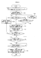
- FIG. 8 is a flowchart illustrating a processing routine of image data generation processing of a second exemplary embodiment.
- a portable radiographic image detection device (hereafter referred to as an electronic cassette) 10 relating to a first exemplary embodiment is disposed to be spaced apart from a radiation generation section 18 , which generates radiation such as X-rays or the like, at a time of capturing of a radiographic image.
- An imaging position for a subject of imaging 19 to be disposed in, is formed between the radiation generation section 18 and the electronic cassette 10 at this time.
- the radiation generation section 18 emits radiation in a radiation amount corresponding to imaging conditions provided in advance or the like.
- the radiation emitted from the radiation generation section 18 passes through the subject of imaging 19 disposed at the imaging position and, carrying image information, is irradiated onto the electronic cassette 10 .
- the electronic cassette 10 is structured with a radiation detector 11 and a handle 16 .
- the radiation detector 11 is covered by a flat plate-form casing 20 that has some thickness and is formed of a material that transmits radiation X.
- a grid 24 Inside the casing 20 , a grid 24 , a radiographic detection panel 26 and a lead plate 28 are arranged in this order from, of the casing 20 , the side of an irradiation surface 22 onto which the radiation X is irradiated.
- the grid 24 eliminates scattered rays of the radiation X that are generated as the radiation X passes through the subject of imaging 19 .
- the radiographic detection panel 26 detects the radiation X.
- the lead plate 28 absorbs back-scattered rays of the radiation X.
- the irradiation surface 22 of the casing 20 may be constituted by the grid 24 .
- a case 30 that accommodates various circuitry including a microcomputer is disposed at one end of the interior of the casing 20 .
- lead plating or the like it is desirable for lead plating or the like to be disposed at the irradiation surface 22 side of the case 30 .
- the handle 16 which serves as a carrying handle for carrying the electronic cassette 10 , is provided at the electronic cassette 10 .
- the handle 16 includes attachment portions 60 a and 60 b for attachment to the radiation detector 11 .
- attachment portions 54 a and 54 b are provided, to which the attachment portions 60 a and 60 b of the handle 16 are detachably connected.
- attachment portions 55 a and 55 b are provided, to which the attachment portions 60 a and 60 b of the handle 16 are detachably connected.
- the handle 16 is attachable/detectable with respect to the radiation detector 11 , and functions as a carrying handle of the electronic cassette 10 when mounted to the radiation detector 11 .
- the handle 16 is formed in a letter U shape.
- the shape functions as a carrying handle, it may be any shape forming a cavity, such as a letter T shape, a letter U shape, a circle or the like.
- it may be a non-penetrated structure, that is, a structure not having a cavity through which a hand (or a portion of the hand such as a finger or the like) is inserted.
- it may be a handle in which a recess is formed for engaging a hand (or a portion of the hand such as a finger or the like), a handle on which a graspable protrusion is formed, or the like.
- the attachment portion for attaching the handle 16 is not limited to the side faces at two edges of the casing 20 of the radiation detector 11 , and may be provided at three edges or four edges.
- Holes for inserting the attachment portions 60 a and 60 b of the handle 16 into the casing 20 are formed at the radiation detector 11 in the attachment portions 54 a , 54 b , 55 a and 55 b .
- the attachment portions 60 a and 60 b at the handle 16 are provided with stoppers 62 at side faces of the handle 16 .
- the stoppers 62 have distal ends with hook forms and are attached to the main body of the handle 16 by resilient members. In a usual state, the hook-form distal ends of the stoppers 62 are at positions protruding beyond the width of the handle 16 . When the portions arrowed in FIG. 3 are pressed, the hook portions are accommodated within the width range of the handle 16 .
- the holes in the casing 20 that are formed to serve as the attachment portions 54 a , 54 b , 55 a and 55 b of the radiation detector 11 function as ventilation apertures for ventilating air inside the radiation detector 11 . Because the attachment portions are provided in a long edge side face and a short edge side face of the electronic cassette 10 , when the handle 16 is mounted to the attachment portions 55 a and 55 b in the long edge side face, the attachment portions 54 a and 54 b in the short edge side face act as ventilation apertures, and when the handle 16 is mounted to the attachment portions 54 a and 54 b in the short edge side face, the attachment portions 55 a and 55 b in the long edge side face act as ventilation apertures.
- the radiation detector 11 is structured by a charge generation layer, which absorbs radiation and converts the same to electric charges, being layered onto a TFT active matrix substrate 32 , which is shown in FIG. 4 .
- the charge generation layer is formed of, for example, noncrystalline a-Se (amorphous selenium) of which selenium is a principal component (for example, a proportional content of at least 50%).
- the charge generation layer When radiation is irradiated thereon, the charge generation layer generates electric charges (electron-hole pairs) thereinside with a charge amount corresponding to the irradiated radiation amount. Thus, the irradiated radiation is converted to electric charges.
- Cumulative capacitances which accumulate the charges generated in the charge generation layer, and pixel portions, which are provided with TFTs for reading out the charges accumulated in the cumulative capacitances, are numerously provided in a matrix form on the TFT active matrix substrate 32 .
- the charges that are generated in the charge generation layer in accordance with irradiation of radiation onto the radiation detector 11 are accumulated in the individual cumulative capacitances of the pixel portions.
- image information carried by the radiation irradiated onto the radiation detector 11 is converted to electric charge information and retained in the radiation detector 11 .
- the gate lines extend in a certain direction (a column direction) and are for turning the TFTs of the pixel portions on and off.
- the data lines are provided in a direction crossing the gate lines (a row direction) and are for reading out the accumulated charges from the cumulative capacitances via the TFTs that have been turned on.
- the respective gate lines are connected to a gate line driver 46 , and the respective data lines are connected to a signal processing section 48 .
- the TFTs of the pixel portions are turned on sequentially, column by column, by signals provided through the gate lines from the gate line driver 46 .
- the charges accumulated in the cumulative capacitances of the pixel portions for which the TFTs have been turned on are propagated through the data lines as charge signals and inputted to the signal processing section 48 .
- the signal processing section 48 is provided with amplifiers and sample and hold circuits, which are provided for each of the data lines.
- the charge signals propagated through the respective data lines are amplified by the amplifiers and then retained in the sample and hold circuits.
- a multiplexer and an A/D converter are provided, in this order, at the output sides of the sample and hold circuits.
- the charge signals retained by the respective sample and hold circuits are sequentially (serially) inputted into the multiplexers and converted to digital image data by the A/D converters.
- An image memory 50 is connected to the signal processing section 48 , and the image data outputted from the A/D converters of the signal processing section 48 is sequentially stored in the image memory 50 .
- the electronic cassette 10 is provided, at the radiation detector 11 , with a mounting detection section 56 , which detects whether or not the handle 16 is mounted to the radiation detector 11 , and a control section 70 .
- a communication section 52 , a reporting section 66 and a power supply section 80 are provided at the handle 16 .
- the communication section 52 is for implementing communication with external devices such as a power supply device and a console or the like.
- the reporting section 66 is for reporting errors relating to operations of the electronic cassette.
- the power supply section 80 provides electrical power to the various circuits and components for operating the electronic cassette 10 .
- the mounting detection section 56 is provided with signal lines from the radiation detector 11 to the handle 16 , which are connected at the attachment portions 54 a , 54 b , 55 a and 55 b , for each of the attachment portions 54 a and 54 b in the short edge side face and the attachment portions 55 a and 55 b in the long edge side face.
- the mounting detection section 56 detects whether or not the handle 16 is mounted to the radiation detector 11 , and whether the handle 16 is mounted to the attachment portions of the short edge side face or the long edge side face, by sensing outputs of the signal lines.
- a constitution may be formed that detects whether or not the handle 16 is mounted to the radiation detector 11 using light such as infrared rays or the like, an electrostatic effect (for example, a method of detecting whether inductors are close together or not by electrostatic capacitance), or the like, and a constitution may be formed that detects when attachment portions relatively reach predetermined positions by sensors.
- the control section 70 is constituted by a microcomputer that includes: a CPU which administers overall control of the electronic cassette 10 ; a ROM which serves as a storage medium that stores a later-described program for image data generation processing; a RAM which serves as a work area and temporarily stores data; and a memory which serves as a storage unit in which various kinds of information are stored.
- the control section is not limited to controlling operations of the whole device as in the present exemplary embodiment, and may be a section that controls operations of a portion of the device.
- the communication section 52 is provided with a connector 52 a , for connecting a coaxial cable 64 for implementing provision of electric power and propagation of data, and a wireless communication section 52 b .
- Wired communications are implemented when a cable is connected to the connector 52 a
- wireless communications are implemented when no cable is connected.
- the reporting section 66 is structured with an LED lamp and a speaker for outputting buzzer sounds, or the like. Errors are reported by plurally providing LED lamps and illuminating LED lamps selected in accordance with categories of error, outputting buzzer sounds with altered rhythms in accordance with categories of error, and the like.
- the power supply section 80 a structure that incorporates a battery (a rechargeable secondary cell) so as not to impair portability of the electronic cassette 10 and provides power to the various circuits and elements from the charged battery will be excellent.
- the power supply section 80 may employ a primary cell as a battery, or may be constituted to be continuously connected to a commercial power source through a power supply cable connected to the connector 52 a of the communication section 52 , rectifying and transforming power provided from the commercial power source and providing this power to the various circuits and elements.
- the power supply section is not limited to a section that provides electric power to constituent sections of the whole device as in the present exemplary embodiment, and may provide electric power to constituent sections of a portion of the device.
- a structure including plural power supply sections is possible.
- FIG. 5A An arrangement in which the long edge of the electronic cassette 10 is parallel with a direction orthogonal to the head-foot direction (a direction from the head toward the feet), as shown in FIG. 5A , is referred to as the horizontal orientation, and an arrangement in which the long edge of the electronic cassette 10 is parallel with the head-foot direction, as shown in FIG. 5B , is referred to as the vertical orientation.
- the electronic cassette 10 When, for example, the electronic cassette 10 is to be inserted between a bed and the subject of imaging 19 , as shown in FIG. 6 , it is usual for an operator 17 of the electronic cassette 10 to grasp the handle 16 and insert the electronic cassette 10 between the bed and the subject of imaging 19 , leading with the side of the opposite edge from the edge at which the handle 16 is mounted.
- the handle 16 In a horizontal orientation case, the handle 16 is easier to handle when attached to the short edge side face of the radiation detector 11 , and in a vertical orientation case, the handle 16 is easier to handle when attached to the long edge side face of the radiation detector 11 .
- image data representing a radiographic image is generated with the long edge at the side at which the attachment portions 55 a and 55 b are provided in the long edge side face being at the top. Further, the attachment portions 54 a and 54 b are provided in the short edge side face that is adjacent in a right-turning direction to the long edge in which the attachment portions 55 a and 55 b are provided. Moreover, the operator 17 inserts the electronic cassette 10 from what is the left-hand side of the subject of imaging 19 if the subject of imaging 19 is face up.
- Which of the edges of the electronic cassette 10 is to correspond with the top of a radiographic image may be specified in advance from the positional relationship of the subject of imaging 19 and the operator 17 or the like. From the relationships between the edge corresponding to the top of the radiographic image and the edges at which the attachment portions are provided, the relationship between a mounting position of the handle 16 and the orientation of a radiographic image may be ascertained.
- the relationship between a mounting position of the handle 16 and the orientation of a radiographic image may be ascertained similarly.
- step 100 it is judged whether or not the handle 16 is mounted to the radiation detector 11 . If mounting is detected, the processing advances to step 102 , and if mounting is not detected, the processing waits until mounting is detected.
- step 102 the mounting position of the handle 16 is acquired by detecting through which of the attachment portions, the attachment portions 54 a and 54 b at the short edge side face or the attachment portions 55 a and 55 b at the long edge side face, the handle 16 is mounted to the radiation detector 11 .
- step 104 it is detected whether or not the coaxial cable 64 is connected to the connector 52 a of the communication section 52 . This judgment is performed by sensing output of a signal line through the coaxial cable 64 . If connection is detected, the processing advances to step 110 , and if no connection is detected, the processing advances to step 106 .
- step 106 it is judged whether or not a remaining battery charge, which is an amount of electric power stored in the power supply section 80 , is stored to an amount of electric power required for performing radiographic imaging. If this amount is stored, the processing advances to step 110 , and if this amount is not stored, the processing advances to step 108 , a battery error is reported by the reporting section 66 , by illuminating LEDs, outputting a buzzer sound or the like, and the processing returns to step 104 .
- a remaining battery charge which is an amount of electric power stored in the power supply section 80 .
- step 110 if, according to the result of the judgment in the above-described step 104 , the coaxial cable 64 is connected to the connector 52 a , implementation of wired communication is specified, and if the coaxial cable 64 is not connected, implementation of wireless communication is specified.
- the electronic cassette 10 is inserted between a bed and the subject of imaging 19 by handling as illustrated in FIG. 6 , then, as illustrated in FIG. 5A and FIG. 5B , the handle 16 is not covered by the subject of imaging 19 . Therefore, in a case of wired communication, connection of the coaxial cable 64 to the connector 52 a provided in the handle 16 is simple, and in a case of wireless communication, propagation failures due to the effect of the human body may be prevented.
- step 112 communication with an external device is implemented by the communication method specified in the above-described step 110 , and information on imaging conditions and the like is acquired and stored in a predetermined area.
- the imaging conditions include information such as a radiation irradiation duration, an image data size and the like.
- step 114 it is judged whether or not irradiation of the radiation has started.
- a radiation irradiation start switch is turned on at an external device or the like and a radiation irradiation start signal is transmitted to the radiation generation section 18 .
- this judgment is determined by whether or not the radiation irradiation start signal, which is also transmitted to the electronic cassette 10 , has been received. If the start signal has been received, the processing advances to step 116 , and if the start signal has not been received, the processing waits until the start signal is received.
- step 116 by reference to the imaging conditions stored in the above-described step 112 , it is judged whether or not the predetermined radiation irradiation duration has passed. If the duration has passed, the processing advances to step 118 , charges accumulated by the radiation irradiation are read out and image data is generated, and the generated image data is stored in the image memory 50 . At this time, information on the handle mounting position that was acquired in step 102 is stored in association with the image data. Because the handle mounting position is associated therewith, when the radiographic image is to be checked or the like, it may be verified whether the electronic cassette 10 was in the horizontal orientation or was in the vertical orientation at the time of imaging. If the predetermined duration has not passed, the processing waits until it has passed.
- step 120 it is judged whether or not the arrangement of the electronic cassette 10 is the horizontal orientation, on the basis of the handle mounting position acquired in step 102 . If the handle mounting position is in the long edge side face, the arrangement is the vertical orientation, the judgment is negative, and the processing advances to step 122 . If the handle mounting position is in the short edge side face, the arrangement is the horizontal orientation, the judgment is positive, and the processing ends.
- step 122 the image data stored in the image memory 50 is read out, and image processing is applied to turn the image data 90° to the right.
- image data is obtained that represents a radiographic image with the head side of the subject of imaging 19 to the top.
- suitable rotation direction and rotation angle image processing are applied in accordance with which edge of the electronic cassette 10 is specified as being at the top of the radiographic image.
- the image data to which the image processing has been applied is again stored in the image memory 50 , and the processing ends.
- a handle provided in consideration of portability is made attachable to a long edge side face and a short edge side face of a radiographic detector.
- the handle may be mounted at a position at which handling of the electronic cassette is easier. Therefore, handling of the electronic cassette is facilitated.
- the orientation of a radiographic image that is generated may be ascertained, by detecting a mounting position of the handle, and image data may be rotated so as to match the orientation of the radiographic image.
- the image processing may be applied when the image data stored in the image memory is being transmitted to an external device.
- an electronic cassette relating to a second exemplary embodiment will be described.
- the electronic cassette 10 relating to the first exemplary embodiment a case has been described in which the orientation of the image is made to match in accordance with the handle mounting position.
- the second exemplary embodiment differs, however, in that the handle mounting position at a current time of imaging is compared with a previous time of imaging.
- the structure of the electronic cassette of the second exemplary embodiment is the same as the structure of the electronic cassette 10 of the first exemplary embodiment, so will not be described.
- a processing routine of image data generation processing of the second exemplary embodiment will be described with reference to FIG. 8 . Processing that is the same as in the image data generation processing of the first exemplary embodiment is assigned the same reference numerals and will not be described.
- the information of imaging conditions and the like is acquired and stored in the predetermined area.
- the imaging conditions acquired in this case include, in addition to information such as the radiation irradiation duration, the image data size and the like, information on the handle mounting position at the previous time of imaging.
- step 200 on the basis of the information on the handle mounting position at the previous time of imaging that is included in the imaging conditions acquired in the above-described step 112 and the information on the handle mounting position that was acquired in the earlier described step 102 , it is judged whether or not the current and the previous handle mounting positions match. If the handle mounting positions match, the processing advances to the processing of step 114 to step 118 and image data is generated.
- the information on the handle mounting position that is stored in association with the image data in step 118 is used, when an image is to be checked or the like, to verify whether the electronic cassette 10 at the time of imaging was in the horizontal orientation or was in the vertical orientation, and is used for the imaging conditions at a next time of imaging, or the like.
- step 202 a handle mounting position error is reported by the reporting section 66 , by illuminating LEDs, outputting a buzzer sound or the like, and the processing returns to step 100 .
- the judgment of step 100 is positive, and the subsequent processing is executed.
- whether the arrangement of the electronic cassette is the horizontal orientation or the vertical orientation may be ascertained by detecting the position at which the handle is mounted to the radiation detector. Therefore, in a case in which imaging should be performed in the same conditions as at a previous time of imaging, for re-imaging or suchlike, or the like, an error is reported if the electronic cassette is arranged in a different arrangement from the previous time of imaging, and imaging with different imaging conditions may be prevented.
Abstract
Description
-
- includes an irradiation surface at which radiation is irradiated and
- is provided, at a plurality of locations on side faces, with attachment portions at which
-
- performs image processing that, on the basis of the position detected by the detection section, rotates the image information so as to correspond to an orientation of a radiographic image represented by the image information outputted from the radiation detection portion, and
- controls so as to store the image information in a storage section.
Claims (6)
Applications Claiming Priority (2)
| Application Number | Priority Date | Filing Date | Title |
|---|---|---|---|
| JP2008209815A JP5553976B2 (en) | 2008-08-18 | 2008-08-18 | Radiation image detection device |
| JP2008-209815 | 2008-08-18 |
Publications (2)
| Publication Number | Publication Date |
|---|---|
| US20100038549A1 US20100038549A1 (en) | 2010-02-18 |
| US8071952B2 true US8071952B2 (en) | 2011-12-06 |
Family
ID=41680645
Family Applications (1)
| Application Number | Title | Priority Date | Filing Date |
|---|---|---|---|
| US12/539,628 Active 2030-04-13 US8071952B2 (en) | 2008-08-18 | 2009-08-12 | Radiographic image detection device |
Country Status (2)
| Country | Link |
|---|---|
| US (1) | US8071952B2 (en) |
| JP (1) | JP5553976B2 (en) |
Cited By (2)
| Publication number | Priority date | Publication date | Assignee | Title |
|---|---|---|---|---|
| US20160029993A1 (en) * | 2012-04-19 | 2016-02-04 | Canon Kabushiki Kaisha | Radiation imaging apparatus and radiation imaging system |
| US11357459B2 (en) * | 2017-04-19 | 2022-06-14 | Canon Kabushiki Kaisha | Radiation imaging apparatus configured to receive a power in a non-contact manner, radiation imaging system, radiation imaging method, and computer-readable medium |
Families Citing this family (9)
| Publication number | Priority date | Publication date | Assignee | Title |
|---|---|---|---|---|
| JP4980317B2 (en) * | 2008-08-22 | 2012-07-18 | パナソニック株式会社 | Information processing device |
| JP2011203724A (en) * | 2010-03-03 | 2011-10-13 | Fujifilm Corp | Portable radiographic image capture device |
| JP5908668B2 (en) * | 2010-04-12 | 2016-04-26 | 富士フイルム株式会社 | Portable radiography system |
| JP5475574B2 (en) * | 2010-07-02 | 2014-04-16 | 富士フイルム株式会社 | Radiation detection element and radiographic imaging device |
| JP5599681B2 (en) * | 2010-08-31 | 2014-10-01 | 富士フイルム株式会社 | Radiation imaging equipment |
| JP5964558B2 (en) * | 2011-06-30 | 2016-08-03 | 富士フイルム株式会社 | Radiation imaging system, connection device, program, and power supply method for connection device |
| JP5854700B2 (en) * | 2011-08-22 | 2016-02-09 | キヤノン株式会社 | X-ray imaging apparatus, handle unit, and X-ray imaging unit |
| JP6428223B2 (en) * | 2014-04-09 | 2018-11-28 | コニカミノルタ株式会社 | Radiation imaging equipment |
| KR102043176B1 (en) * | 2018-03-06 | 2019-11-12 | 주식회사 뷰웍스 | A Handle for radiation detectors |
Citations (2)
| Publication number | Priority date | Publication date | Assignee | Title |
|---|---|---|---|---|
| JP2004077641A (en) | 2002-08-13 | 2004-03-11 | Canon Inc | Electronic cassette |
| US6805484B2 (en) * | 2002-12-19 | 2004-10-19 | Canon U.S.A., Inc. | Handle for digital radiography panel |
Family Cites Families (3)
| Publication number | Priority date | Publication date | Assignee | Title |
|---|---|---|---|---|
| US5661309A (en) * | 1992-12-23 | 1997-08-26 | Sterling Diagnostic Imaging, Inc. | Electronic cassette for recording X-ray images |
| JP5020460B2 (en) * | 2000-06-27 | 2012-09-05 | キヤノン株式会社 | Digital X-ray imaging device |
| JP2007117754A (en) * | 2003-02-10 | 2007-05-17 | Kanazawa Inst Of Technology | Bag |
-
2008
- 2008-08-18 JP JP2008209815A patent/JP5553976B2/en active Active
-
2009
- 2009-08-12 US US12/539,628 patent/US8071952B2/en active Active
Patent Citations (2)
| Publication number | Priority date | Publication date | Assignee | Title |
|---|---|---|---|---|
| JP2004077641A (en) | 2002-08-13 | 2004-03-11 | Canon Inc | Electronic cassette |
| US6805484B2 (en) * | 2002-12-19 | 2004-10-19 | Canon U.S.A., Inc. | Handle for digital radiography panel |
Cited By (3)
| Publication number | Priority date | Publication date | Assignee | Title |
|---|---|---|---|---|
| US20160029993A1 (en) * | 2012-04-19 | 2016-02-04 | Canon Kabushiki Kaisha | Radiation imaging apparatus and radiation imaging system |
| US10531856B2 (en) * | 2012-04-19 | 2020-01-14 | Canon Kabushiki Kaisha | Radiation imaging apparatus and radiation imaging system |
| US11357459B2 (en) * | 2017-04-19 | 2022-06-14 | Canon Kabushiki Kaisha | Radiation imaging apparatus configured to receive a power in a non-contact manner, radiation imaging system, radiation imaging method, and computer-readable medium |
Also Published As
| Publication number | Publication date |
|---|---|
| JP5553976B2 (en) | 2014-07-23 |
| US20100038549A1 (en) | 2010-02-18 |
| JP2010044324A (en) | 2010-02-25 |
Similar Documents
| Publication | Publication Date | Title |
|---|---|---|
| US8071952B2 (en) | Radiographic image detection device | |
| US8053738B2 (en) | Radiographic image detection device and radiographic image detection system | |
| US8237127B2 (en) | Electronic cassette | |
| US7581885B2 (en) | Method and system of aligning x-ray detector for data acquisition | |
| CN101765405B (en) | Radiation detecting cassette and radiation image picking-up system | |
| US7777192B2 (en) | Cassette system | |
| US8053737B2 (en) | Radiographic image detection device and radiographic image detection system | |
| US7807976B2 (en) | Radiation image detection apparatus and radiation image photographing system | |
| US8265225B2 (en) | Radiation imaging system, power supplying apparatus, charging apparatus, and radiation imaging method | |
| US20100044574A1 (en) | Portable radiation detector | |
| JP5090245B2 (en) | Electronic cassette charging device, electronic cassette charging system, and electronic cassette charging method | |
| US7740405B2 (en) | Cassette | |
| US20090026377A1 (en) | Cassette | |
| US20110293070A1 (en) | Portable radiographic apparatus system | |
| JP5296431B2 (en) | Radiation imaging system | |
| EP2624161A1 (en) | Electronic cassette and electronic cassette device | |
| US7977644B2 (en) | Portable radiation detector | |
| JP2010025984A (en) | Portable radiation detector | |
| JP2009205103A (en) | Portable radiograph conversion device | |
| JP5554257B2 (en) | Storage device and radiographic imaging system | |
| JP5679926B2 (en) | Radiographic imaging system, connection device, fall detection method and program for radiographic imaging device | |
| JP2009028332A (en) | Cassette and radiation image photographing system | |
| JP2009276390A (en) | Radiation ray image radiating device and radiation ray image detecting system | |
| JP2009028374A (en) | Radiation image photographing system | |
| JP5964558B2 (en) | Radiation imaging system, connection device, program, and power supply method for connection device |
Legal Events
| Date | Code | Title | Description |
|---|---|---|---|
| AS | Assignment |
Owner name: FUJIFILM CORPORATION,JAPAN Free format text: ASSIGNMENT OF ASSIGNORS INTEREST;ASSIGNORS:NISHINO, NAOYUKI;YOSHIDA, YUTAKA;OHTA, YASUNORI;AND OTHERS;REEL/FRAME:023093/0346 Effective date: 20090722 Owner name: FUJIFILM CORPORATION, JAPAN Free format text: ASSIGNMENT OF ASSIGNORS INTEREST;ASSIGNORS:NISHINO, NAOYUKI;YOSHIDA, YUTAKA;OHTA, YASUNORI;AND OTHERS;REEL/FRAME:023093/0346 Effective date: 20090722 |
|
| STCF | Information on status: patent grant |
Free format text: PATENTED CASE |
|
| FEPP | Fee payment procedure |
Free format text: PAYOR NUMBER ASSIGNED (ORIGINAL EVENT CODE: ASPN); ENTITY STATUS OF PATENT OWNER: LARGE ENTITY |
|
| FPAY | Fee payment |
Year of fee payment: 4 |
|
| MAFP | Maintenance fee payment |
Free format text: PAYMENT OF MAINTENANCE FEE, 8TH YEAR, LARGE ENTITY (ORIGINAL EVENT CODE: M1552); ENTITY STATUS OF PATENT OWNER: LARGE ENTITY Year of fee payment: 8 |
|
| MAFP | Maintenance fee payment |
Free format text: PAYMENT OF MAINTENANCE FEE, 12TH YEAR, LARGE ENTITY (ORIGINAL EVENT CODE: M1553); ENTITY STATUS OF PATENT OWNER: LARGE ENTITY Year of fee payment: 12 |