US8071043B2 - Electrode cap for electrical discharge reactor - Google Patents
Electrode cap for electrical discharge reactor Download PDFInfo
- Publication number
- US8071043B2 US8071043B2 US12/016,276 US1627608A US8071043B2 US 8071043 B2 US8071043 B2 US 8071043B2 US 1627608 A US1627608 A US 1627608A US 8071043 B2 US8071043 B2 US 8071043B2
- Authority
- US
- United States
- Prior art keywords
- cap
- electrode
- base cap
- tube
- base
- Prior art date
- Legal status (The legal status is an assumption and is not a legal conclusion. Google has not performed a legal analysis and makes no representation as to the accuracy of the status listed.)
- Expired - Fee Related, expires
Links
Images


Classifications
-
- H—ELECTRICITY
- H01—ELECTRIC ELEMENTS
- H01J—ELECTRIC DISCHARGE TUBES OR DISCHARGE LAMPS
- H01J5/00—Details relating to vessels or to leading-in conductors common to two or more basic types of discharge tubes or lamps
- H01J5/50—Means forming part of the tube or lamps for the purpose of providing electrical connection to it
Definitions
- the invention is in the field of electrical discharge reactors.
- Electrical discharge reactors are used in ozone generators, UV disinfection devices, and pollution control devices.
- An example is described in U.S. Pat. No. 6,132,692, which is not admitted to being prior art by its mention in this Background section.
- Some of the different types of electrical discharges include glow, corona, and dielectric barrier discharge.
- dielectric barrier discharge reactors include a high voltage electrode, which is usually a wire or thin rod. This is disposed inside a tube that is typically made of glass or fused quartz. The tube forms the dielectric barrier. The inside of the tube may be filled with a gas, air, or a vacuum.
- Reactors are made by providing a plurality of tube and electrode assemblies physically and electrically connected to plates.
- the electrode assemblies were capped with a metal cap on one end and secured to the plate with an extension and a screw. The electrode wire sticks out the end of the cap, and can be secured by welding.
- This configuration has several disadvantages. First, centering the electrode assembly is not assured, and misalignment is possible. It is also difficult to secure the screws if there are many electrode assemblies close together. The electrode must make a sharp bend, which may damage it. Furthermore, the sharp end of the wire and corners of the cap might generate corona, which must be avoided. The tube seal is also susceptible to damage from vibration and rough handling. Finally, the old configuration does not allow for thermal expansion. These disadvantages tend to cause breakage and failure of the electrode.
- an electrode cap for an electrical discharge reactor that is easy to install, assures proper alignment, inhibits corona, provides some cushion to avoid damages, and permits thermal expansion.
- the invention is an apparatus that satisfies the need for an electrode cap for an electrical discharge reactor that is easy to install, assures proper alignment, inhibits corona, provides some cushion to avoid damages, and permits thermal expansion.
- the invention is an electrode cap comprising a horseshoe-shaped conductor clip comprising an opening at a closed end for receiving an electrode, the conductor clip adapted to fit over a tube crimp; a substantially cylindrical base cap comprising an elongated bump at one end of the base cap parallel to the axis of the base cap; and a substantially cylindrical top cap closed on one end, having an inside diameter larger than the outside diameter of the base cap; and a spring means for pressing a plate against the base cap.
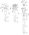
- FIG. 1 is a cutaway view of an electrode cap of the present invention attached to a plate.
- FIG. 2 is a plan view of the electrode cap without the plate.
- FIG. 3 is a cutaway plan view.
- FIG. 4 is an exploded plan view.
- FIG. 5 is a side elevation of the electrode cap without the plate.
- FIG. 6 is a cutaway side elevation.
- FIG. 7 is an exploded side elevation.
- Electrode Cap Assembly 102 Top Cap 104 Base Cap 106 Cap Spring 108 Conductor Clip 110 Wave Spring 112 Plate 114 Tube 116 Electrode 118 Crimp 120 Flap 122 Window 124 Bump
- the invention is an electrode cap comprising a horseshoe-shaped conductor clip comprising an opening at a closed end for receiving an electrode, the conductor clip adapted to fit over a tube crimp; a substantially cylindrical base cap comprising an elongated bump at one end of the base cap parallel to the axis of the base cap; and a substantially cylindrical top cap closed on one end, having an inside diameter larger than the outside diameter of the base cap; and a spring means for pressing a plate against the base cap.
- an electrode tube comprising a tube 114 and an electrode 116 disposed within the tube 114 .
- the tube 114 is usually hollow, and can be filled with a gas to form a gas filled electrode (“GFE”).
- GFE gas filled electrode
- One end of the tube has a crimp 118 that is capable of containing gas within the tube 114 , while the electrode 116 extends beyond the crimp.
- An electrode cap assembly 100 is provided, that is made up of several parts. The parts are preferably made of an electrically conductive material, like stainless steel.
- a conductor clip 108 is secured to the crimp 118 .
- the conductor clip is horseshoe shaped in cross section.
- the closed end of the conductor clip 108 has an opening for receiving the electrode.
- the conductor clip 108 is sized to fit over the crimp 118 .
- a base cap 104 is provided. It is substantially cylindrical in that it has two sections of different diameters. The smaller diameter is sized to just slide over the outside diameter of the tube 114 . The smaller diameter also has one or more elongated bumps 124 a , 124 b parallel to the axis of the base cap 104 . These bumps are for locking the electrode assembly 100 into a plate 112 .
- a substantially cylindrical top cap 102 is also provided.
- the top cap is closed on one end and open on the other.
- the inside diameter of the top cap 102 is sized to have a sliding fit with the outside diameter of the base cap 104 to provide an electrical connection and inhibit contamination.
- the junction of the top cap 102 cylinder and closed end is rounded, as is shown in FIG. 1 .
- the rounded quality inhibits for the formation of corona.
- a helical compression cap spring 106 can be provided that has an outside diameter smaller than the inside diameter of the base cap 104 .
- the cap spring 106 provides electrical connection and compression between the conductor clip 108 and top cap 102 .
- a spring means 110 is placed over the base cap 104 .
- the spring means 110 is preferably a wave spring, such as those conforming to DIN 137 , although other springs could be used.
- Other spring means could be used, such as a helical spring, conical washer, or Belleville washer.
- the spring means 110 keeps the electrode assembly 100 secure in the plate 112 after being inserted and twisted to lock it in place.
- a typical plate that would be used in this application is 12 gauge stainless steel.
- a wave spring is shown compressed flat.
- FIG. 2 is a plan view of the electrode assembly 100 without the plate.
- the spring means 110 is shown as an uncompressed wave spring. This view also shows a flap 120 of the base cap 104 that has been received and secured by a window in the top cap 102 .
- FIG. 3 is a cutaway view of the plan view of FIG. 2 .
- FIG. 4 is an exploded view of the plan view.
- the flap 120 of the base cap 104 can be a rectangular section punched out of the base cap, and extending outward toward the bump.
- the window 122 of the top cap 102 is sized to receive and secure the base cap flap 120 .
- FIG. 5 is a side elevation of the electrode cap of the present invention.
- the configuration of the elongated bump 124 a is shown.
- the bump is on the end of the base cap 104 with the smaller diameter, and is parallel to the axis of the base cap. More than one bump can be provided.
- the base cap flap 120 b and window 122 a are shown. Since the flap extends through the top cap 102 , the top cap is locked while under compression. The top cap can be released by compressing the top cap and pressing in the flap so that it clears the window. Other mechanisms that are known in the art can be used to secure the top cap 102 .
- FIG. 6 is the cutaway view of FIG. 5 , and exposes an elongated bump 124 b placed opposite that shown in FIG. 5 . It is clear to see how the conductor clip 108 fits over the crimp 118 .
- FIG. 7 is an exploded view of the side elevation. Details of two base cap flaps 120 a , 120 b and the top cap windows 122 a , 122 b are shown in this view.
- the electrode assembly is installed by placing a horseshoe-shaped conductor clip 108 over the crimp 118 ; securing the electrode 116 to the conductor clip 108 ; placing a substantially cylindrical base cap 104 over the tube 114 at the crimp end, the base cap 104 having an elongated bump 124 at one end of the base cap 104 parallel to the axis of the base cap, and having an external flap 120 extending toward the bump 124 . Then one places a helical compression cap spring 106 inside the base cap 104 and in contact with the conductor clip 108 . Next, one assembles the top cap 102 so that the base cap flap 120 engages the top cap window 122 and locks.
- the next step is assembling a spring means 110 over the base cap 104 .
- Assembling to a plate 112 is completed by inserting the electrode assembly 100 into the plate 112 having a hole to receive the base cap 104 and a groove to receive the bump 124 and twisting the electrode assembly to lock it in place.
Landscapes
- Physical Or Chemical Processes And Apparatus (AREA)
Abstract
An electrode cap having a horseshoe-shaped conductor clip that has an opening at a closed end for receiving an electrode, the conductor clip fitted over a tube crimp; a cylindrical base cap having an elongated bump at one end of the base cap parallel to the axis of the base cap; and a cylindrical top cap closed on one end, having an inside diameter larger than the outside diameter of the base cap; and a spring for pressing a plate against the base cap.
Description
1. Field of the Invention
The invention is in the field of electrical discharge reactors.
2. Description of the Related Art
Electrical discharge reactors are used in ozone generators, UV disinfection devices, and pollution control devices. An example is described in U.S. Pat. No. 6,132,692, which is not admitted to being prior art by its mention in this Background section. Some of the different types of electrical discharges include glow, corona, and dielectric barrier discharge.
Some of the common parts of dielectric barrier discharge reactors include a high voltage electrode, which is usually a wire or thin rod. This is disposed inside a tube that is typically made of glass or fused quartz. The tube forms the dielectric barrier. The inside of the tube may be filled with a gas, air, or a vacuum.
Reactors are made by providing a plurality of tube and electrode assemblies physically and electrically connected to plates. In the past, the electrode assemblies were capped with a metal cap on one end and secured to the plate with an extension and a screw. The electrode wire sticks out the end of the cap, and can be secured by welding.
This configuration has several disadvantages. First, centering the electrode assembly is not assured, and misalignment is possible. It is also difficult to secure the screws if there are many electrode assemblies close together. The electrode must make a sharp bend, which may damage it. Furthermore, the sharp end of the wire and corners of the cap might generate corona, which must be avoided. The tube seal is also susceptible to damage from vibration and rough handling. Finally, the old configuration does not allow for thermal expansion. These disadvantages tend to cause breakage and failure of the electrode.
What is needed, therefore, is an electrode cap for an electrical discharge reactor that is easy to install, assures proper alignment, inhibits corona, provides some cushion to avoid damages, and permits thermal expansion.
The invention is an apparatus that satisfies the need for an electrode cap for an electrical discharge reactor that is easy to install, assures proper alignment, inhibits corona, provides some cushion to avoid damages, and permits thermal expansion. The invention is an electrode cap comprising a horseshoe-shaped conductor clip comprising an opening at a closed end for receiving an electrode, the conductor clip adapted to fit over a tube crimp; a substantially cylindrical base cap comprising an elongated bump at one end of the base cap parallel to the axis of the base cap; and a substantially cylindrical top cap closed on one end, having an inside diameter larger than the outside diameter of the base cap; and a spring means for pressing a plate against the base cap. These and other features, aspects, and advantages of the present invention will become better understood with regard to the following description, claims, and accompanying drawings.
| TABLE OF |
| 100 | Electrode Cap |
| 102 | |
| 104 | |
| 106 | Cap Spring |
| 108 | |
| 110 | |
| 112 | |
| 114 | |
| 116 | Electrode |
| 118 | Crimp |
| 120 | Flap |
| 122 | Window |
| 124 | Bump |
The invention is an electrode cap comprising a horseshoe-shaped conductor clip comprising an opening at a closed end for receiving an electrode, the conductor clip adapted to fit over a tube crimp; a substantially cylindrical base cap comprising an elongated bump at one end of the base cap parallel to the axis of the base cap; and a substantially cylindrical top cap closed on one end, having an inside diameter larger than the outside diameter of the base cap; and a spring means for pressing a plate against the base cap.
Turning to FIG. 1 an electrode tube is provided comprising a tube 114 and an electrode 116 disposed within the tube 114. The tube 114 is usually hollow, and can be filled with a gas to form a gas filled electrode (“GFE”). One end of the tube has a crimp 118 that is capable of containing gas within the tube 114, while the electrode 116 extends beyond the crimp.
An electrode cap assembly 100 is provided, that is made up of several parts. The parts are preferably made of an electrically conductive material, like stainless steel. First, a conductor clip 108 is secured to the crimp 118. The conductor clip is horseshoe shaped in cross section. The closed end of the conductor clip 108 has an opening for receiving the electrode. The conductor clip 108 is sized to fit over the crimp 118.
A base cap 104 is provided. It is substantially cylindrical in that it has two sections of different diameters. The smaller diameter is sized to just slide over the outside diameter of the tube 114. The smaller diameter also has one or more elongated bumps 124 a, 124 b parallel to the axis of the base cap 104. These bumps are for locking the electrode assembly 100 into a plate 112.
A substantially cylindrical top cap 102 is also provided. The top cap is closed on one end and open on the other. The inside diameter of the top cap 102 is sized to have a sliding fit with the outside diameter of the base cap 104 to provide an electrical connection and inhibit contamination. Preferably, the junction of the top cap 102 cylinder and closed end is rounded, as is shown in FIG. 1 . The rounded quality inhibits for the formation of corona.
A helical compression cap spring 106 can be provided that has an outside diameter smaller than the inside diameter of the base cap 104. The cap spring 106 provides electrical connection and compression between the conductor clip 108 and top cap 102. One can also use a conical helical spring with the point of the cone contacting the conductor clip 108, or other types of springs that are known in the art.
A spring means 110 is placed over the base cap 104. The spring means 110 is preferably a wave spring, such as those conforming to DIN 137, although other springs could be used. Other spring means could be used, such as a helical spring, conical washer, or Belleville washer.
The spring means 110 keeps the electrode assembly 100 secure in the plate 112 after being inserted and twisted to lock it in place. A typical plate that would be used in this application is 12 gauge stainless steel. In FIG. 1 , a wave spring is shown compressed flat.
In this view, details of the base cap flap 120 b and window 122 a are shown. Since the flap extends through the top cap 102, the top cap is locked while under compression. The top cap can be released by compressing the top cap and pressing in the flap so that it clears the window. Other mechanisms that are known in the art can be used to secure the top cap 102.
In operation, the electrode assembly is installed by placing a horseshoe-shaped conductor clip 108 over the crimp 118; securing the electrode 116 to the conductor clip 108; placing a substantially cylindrical base cap 104 over the tube 114 at the crimp end, the base cap 104 having an elongated bump 124 at one end of the base cap 104 parallel to the axis of the base cap, and having an external flap 120 extending toward the bump 124. Then one places a helical compression cap spring 106 inside the base cap 104 and in contact with the conductor clip 108. Next, one assembles the top cap 102 so that the base cap flap 120 engages the top cap window 122 and locks. The next step is assembling a spring means 110 over the base cap 104. Assembling to a plate 112 is completed by inserting the electrode assembly 100 into the plate 112 having a hole to receive the base cap 104 and a groove to receive the bump 124 and twisting the electrode assembly to lock it in place.
Although the preferred embodiments of the present invention have been described herein, the above description is merely illustrative. Further modification of the invention herein disclosed will occur to those skilled in the respective arts and all such modifications are deemed to be within the scope of the invention as defined by the appended claims.
Claims (9)
1. An electrode cap for removably securing an electrode to a plate comprising:
a tube comprising a tube crimp at one end;
a horseshoe-shaped conductor clip comprising an opening at a closed end for receiving an electrode, the conductor clip adapted to fit over a tube crimp;
a substantially cylindrical base cap comprising an elongated bump at one end of the base cap parallel to the axis of the base cap;
a substantially cylindrical top cap closed on one end, having an inside diameter larger than the outside diameter of the base cap;
a spring means for pressing a plate against the base cap; and
an electrode disposed within the tube and crimp adapted to be coupled with the conductor clip.
2. The electrode cap of claim 1 , the base cap further comprising an external flap extending toward the elongated bump.
3. The electrode cap of claim 2 , the top cap further comprising a window sized to receive and retain the external flap and to provide an electrical connection when assembled.
4. The electrode cap of claim 1 , wherein the spring means is a wave spring.
5. The electrode cap of claim 1 , wherein the conductor clip, base cap, top cap, and spring means are made from an electrically conductive material.
6. The electrode cap of claim 1 , further comprising a helical compression cap spring having an outside diameter smaller than the top cap inside diameter for providing compression and electrical connection between the top cap and the conductor clip when assembled.
7. The electrode cap of claim 6 , further comprising an electrically conductive plate for removably securing the electrode and providing electricity.
8. The electrode cap of claim 6 , wherein the substantially cylindrical top cap comprises a substantially cylindrical portion, a closed end portion and a junction between the substantially cylindrical portion and the closed end portion, wherein the junction is rounded so as to prevent the formation of corona in operation.
9. A method of removably securing an electrode in a place comprising the steps of:
providing an electrode tube comprising a tube, a crimp at one end of the tube, and an electrode disposed within the tube and crimp;
placing a horseshoe-shaped conductor clip over the crimp;
securing the electrode to the conductor clip;
placing a substantially cylindrical base cap over the tube at the crimp end, the base cap having an elongated bump at one end of the base cap parallel to the axis of the base cap, and having an external flap extending toward the bump;
placing a helical compression cap spring inside the base cap and in contact with the conductor clip;
assembling a substantially cylindrical top cap that is closed on one end, having an inside diameter larger than the outside diameter of the base cap and having a window sized to receive and retain the base cap flap, so that the base cap flap engages the window and locks;
assembling a wave spring over the base cap;
inserting the electrode assembly into a plate having a hole to receive the base cap and a groove to receive the bump; and
twisting the electrode assembly to lock it in place.
Priority Applications (1)
| Application Number | Priority Date | Filing Date | Title |
|---|---|---|---|
| US12/016,276 US8071043B2 (en) | 2008-01-18 | 2008-01-18 | Electrode cap for electrical discharge reactor |
Applications Claiming Priority (1)
| Application Number | Priority Date | Filing Date | Title |
|---|---|---|---|
| US12/016,276 US8071043B2 (en) | 2008-01-18 | 2008-01-18 | Electrode cap for electrical discharge reactor |
Publications (2)
| Publication Number | Publication Date |
|---|---|
| US20090184620A1 US20090184620A1 (en) | 2009-07-23 |
| US8071043B2 true US8071043B2 (en) | 2011-12-06 |
Family
ID=40875920
Family Applications (1)
| Application Number | Title | Priority Date | Filing Date |
|---|---|---|---|
| US12/016,276 Expired - Fee Related US8071043B2 (en) | 2008-01-18 | 2008-01-18 | Electrode cap for electrical discharge reactor |
Country Status (1)
| Country | Link |
|---|---|
| US (1) | US8071043B2 (en) |
Cited By (4)
| Publication number | Priority date | Publication date | Assignee | Title |
|---|---|---|---|---|
| US9067837B2 (en) | 2013-03-15 | 2015-06-30 | Three D Stack, LLC | Cleaning stack gas |
| US9153427B2 (en) | 2012-12-18 | 2015-10-06 | Agilent Technologies, Inc. | Vacuum ultraviolet photon source, ionization apparatus, and related methods |
| US9919269B2 (en) | 2013-03-15 | 2018-03-20 | 3D Clean Coal Emissions Stack Llc | Clean coal stack |
| US10486105B2 (en) | 2016-05-14 | 2019-11-26 | 3D Clean Coal Emissions Stack, Llc | Clean gas stack |
Families Citing this family (2)
| Publication number | Priority date | Publication date | Assignee | Title |
|---|---|---|---|---|
| USD959524S1 (en) * | 2020-09-28 | 2022-08-02 | Thomas Chad Middlebrook | Lid for welding electrode storage |
| JP7549294B2 (en) * | 2021-02-03 | 2024-09-11 | ウシオ電機株式会社 | Excimer Lamp |
Citations (6)
| Publication number | Priority date | Publication date | Assignee | Title |
|---|---|---|---|---|
| US4155827A (en) * | 1977-06-30 | 1979-05-22 | Robert Bosch Gmbh | Electro-chemical sensor construction |
| US6132692A (en) | 1996-10-09 | 2000-10-17 | Powerspan Corp. | Barrier discharge conversion of SO2 and NOx to acids |
| US20040129566A1 (en) * | 2002-12-20 | 2004-07-08 | Denso Corporation | Gas sensor having improved structure for minimizing thermal damage |
| US20050034973A1 (en) | 2001-11-15 | 2005-02-17 | Timothy Kelley | Discharge reactor fuse link |
| US20060148300A1 (en) * | 2004-06-18 | 2006-07-06 | Advanced Connectek Inc. | USB connector with latching arrangement |
| US20070243760A1 (en) * | 2006-04-13 | 2007-10-18 | Ngk Spark Plug Co., Ltd. | Gas sensor |
-
2008
- 2008-01-18 US US12/016,276 patent/US8071043B2/en not_active Expired - Fee Related
Patent Citations (6)
| Publication number | Priority date | Publication date | Assignee | Title |
|---|---|---|---|---|
| US4155827A (en) * | 1977-06-30 | 1979-05-22 | Robert Bosch Gmbh | Electro-chemical sensor construction |
| US6132692A (en) | 1996-10-09 | 2000-10-17 | Powerspan Corp. | Barrier discharge conversion of SO2 and NOx to acids |
| US20050034973A1 (en) | 2001-11-15 | 2005-02-17 | Timothy Kelley | Discharge reactor fuse link |
| US20040129566A1 (en) * | 2002-12-20 | 2004-07-08 | Denso Corporation | Gas sensor having improved structure for minimizing thermal damage |
| US20060148300A1 (en) * | 2004-06-18 | 2006-07-06 | Advanced Connectek Inc. | USB connector with latching arrangement |
| US20070243760A1 (en) * | 2006-04-13 | 2007-10-18 | Ngk Spark Plug Co., Ltd. | Gas sensor |
Cited By (5)
| Publication number | Priority date | Publication date | Assignee | Title |
|---|---|---|---|---|
| US9153427B2 (en) | 2012-12-18 | 2015-10-06 | Agilent Technologies, Inc. | Vacuum ultraviolet photon source, ionization apparatus, and related methods |
| US9067837B2 (en) | 2013-03-15 | 2015-06-30 | Three D Stack, LLC | Cleaning stack gas |
| US9737849B2 (en) | 2013-03-15 | 2017-08-22 | 3 D Clean Coal Emissions Stack, Llc | Cleaning stack gas |
| US9919269B2 (en) | 2013-03-15 | 2018-03-20 | 3D Clean Coal Emissions Stack Llc | Clean coal stack |
| US10486105B2 (en) | 2016-05-14 | 2019-11-26 | 3D Clean Coal Emissions Stack, Llc | Clean gas stack |
Also Published As
| Publication number | Publication date |
|---|---|
| US20090184620A1 (en) | 2009-07-23 |
Similar Documents
| Publication | Publication Date | Title |
|---|---|---|
| US8071043B2 (en) | Electrode cap for electrical discharge reactor | |
| CN1405807A (en) | Insulating operating rod | |
| CN117368620B (en) | Composite insulator aging experimental device | |
| DE102012109762B4 (en) | Corona ignition device with gastight HF connector | |
| CN104685588B (en) | Device for airtight guiding of conductors through housing walls | |
| RU2285968C2 (en) | Method for manufacturing high-voltage bushing insulator | |
| DE102008000494A1 (en) | Gas tight electric bushing for use in gas-cooled electrical generator, has sleeve with front side loosely surrounding electrical conductor, and bush, funnel-shaped element and sleeve consisting of electric insulating material | |
| JP4659370B2 (en) | Active part of the arrester | |
| CN101359814A (en) | Electrical connection device between two medium- or high-voltage cells and distribution substation containing at least one such device | |
| CN106952701A (en) | Overvoltage protection arrester | |
| EP1147534B1 (en) | Discharge lamp | |
| DE102014103387B4 (en) | Process for producing a corona ignition device | |
| CN118112380A (en) | Environment-friendly gas insulation equipment component insulation test fixture | |
| CN120188235A (en) | Arrester modules and arresters | |
| CN117558520A (en) | lightning arrester | |
| CN2513223Y (en) | Closed high voltage fuse | |
| JP4550750B2 (en) | Arresta | |
| USRE29391E (en) | Surge protector assembly | |
| CN103608870B (en) | Suspension Mechanism of Cathode Shell of Electron Beam Device | |
| JP2004335140A (en) | Apparatus and method for inspecting spark plug integrated with coil | |
| DE102010002769A1 (en) | Electric lamp with an outer bulb and a built-in lamp and associated manufacturing method | |
| CN121460385A (en) | Capacitor bank | |
| US2231490A (en) | Mounting for electron tubes | |
| CN113009190B (en) | Single-branch insulation pull rod test tool and test equipment for GIS | |
| KR102152703B1 (en) | Current Lead for High Voltage Apparatus |
Legal Events
| Date | Code | Title | Description |
|---|---|---|---|
| AS | Assignment |
Owner name: POWERSPAN CORP., NEW HAMPSHIRE Free format text: ASSIGNMENT OF ASSIGNORS INTEREST;ASSIGNORS:COMO, KEVIN;STERNDALE, ROBERT;CROTO, KEITH;AND OTHERS;REEL/FRAME:020382/0338 Effective date: 20080116 |
|
| REMI | Maintenance fee reminder mailed | ||
| LAPS | Lapse for failure to pay maintenance fees | ||
| STCH | Information on status: patent discontinuation |
Free format text: PATENT EXPIRED DUE TO NONPAYMENT OF MAINTENANCE FEES UNDER 37 CFR 1.362 |
|
| STCH | Information on status: patent discontinuation |
Free format text: PATENT EXPIRED DUE TO NONPAYMENT OF MAINTENANCE FEES UNDER 37 CFR 1.362 |
|
| FP | Lapsed due to failure to pay maintenance fee |
Effective date: 20151206 |