US8070945B2 - Filtration module including unitary filter cartridge-bowl construction - Google Patents
Filtration module including unitary filter cartridge-bowl construction Download PDFInfo
- Publication number
- US8070945B2 US8070945B2 US12/215,539 US21553908A US8070945B2 US 8070945 B2 US8070945 B2 US 8070945B2 US 21553908 A US21553908 A US 21553908A US 8070945 B2 US8070945 B2 US 8070945B2
- Authority
- US
- United States
- Prior art keywords
- cartridge
- bowl
- collar
- filtration
- filtration module
- Prior art date
- Legal status (The legal status is an assumption and is not a legal conclusion. Google has not performed a legal analysis and makes no representation as to the accuracy of the status listed.)
- Expired - Fee Related, expires
Links
Images


Classifications
-
- B—PERFORMING OPERATIONS; TRANSPORTING
- B01—PHYSICAL OR CHEMICAL PROCESSES OR APPARATUS IN GENERAL
- B01D—SEPARATION
- B01D46/00—Filters or filtering processes specially modified for separating dispersed particles from gases or vapours
- B01D46/88—Replacing filter elements
-
- B—PERFORMING OPERATIONS; TRANSPORTING
- B01—PHYSICAL OR CHEMICAL PROCESSES OR APPARATUS IN GENERAL
- B01D—SEPARATION
- B01D29/00—Filters with filtering elements stationary during filtration, e.g. pressure or suction filters, not covered by groups B01D24/00 - B01D27/00; Filtering elements therefor
- B01D29/11—Filters with filtering elements stationary during filtration, e.g. pressure or suction filters, not covered by groups B01D24/00 - B01D27/00; Filtering elements therefor with bag, cage, hose, tube, sleeve or like filtering elements
- B01D29/13—Supported filter elements
- B01D29/15—Supported filter elements arranged for inward flow filtration
- B01D29/21—Supported filter elements arranged for inward flow filtration with corrugated, folded or wound sheets
-
- B—PERFORMING OPERATIONS; TRANSPORTING
- B01—PHYSICAL OR CHEMICAL PROCESSES OR APPARATUS IN GENERAL
- B01D—SEPARATION
- B01D29/00—Filters with filtering elements stationary during filtration, e.g. pressure or suction filters, not covered by groups B01D24/00 - B01D27/00; Filtering elements therefor
- B01D29/96—Filters with filtering elements stationary during filtration, e.g. pressure or suction filters, not covered by groups B01D24/00 - B01D27/00; Filtering elements therefor in which the filtering elements are moved between filtering operations; Particular measures for removing or replacing the filtering elements; Transport systems for filters
-
- B—PERFORMING OPERATIONS; TRANSPORTING
- B01—PHYSICAL OR CHEMICAL PROCESSES OR APPARATUS IN GENERAL
- B01D—SEPARATION
- B01D35/00—Filtering devices having features not specifically covered by groups B01D24/00 - B01D33/00, or for applications not specifically covered by groups B01D24/00 - B01D33/00; Auxiliary devices for filtration; Filter housing constructions
- B01D35/30—Filter housing constructions
- B01D35/306—Filter mounting adapter
-
- B—PERFORMING OPERATIONS; TRANSPORTING
- B01—PHYSICAL OR CHEMICAL PROCESSES OR APPARATUS IN GENERAL
- B01D—SEPARATION
- B01D2201/00—Details relating to filtering apparatus
- B01D2201/30—Filter housing constructions
- B01D2201/301—Details of removable closures, lids, caps, filter heads
- B01D2201/302—Details of removable closures, lids, caps, filter heads having inlet or outlet ports
-
- B—PERFORMING OPERATIONS; TRANSPORTING
- B01—PHYSICAL OR CHEMICAL PROCESSES OR APPARATUS IN GENERAL
- B01D—SEPARATION
- B01D2201/00—Details relating to filtering apparatus
- B01D2201/30—Filter housing constructions
- B01D2201/301—Details of removable closures, lids, caps, filter heads
- B01D2201/305—Snap, latch or clip connecting means
-
- B—PERFORMING OPERATIONS; TRANSPORTING
- B01—PHYSICAL OR CHEMICAL PROCESSES OR APPARATUS IN GENERAL
- B01D—SEPARATION
- B01D2201/00—Details relating to filtering apparatus
- B01D2201/40—Special measures for connecting different parts of the filter
- B01D2201/4015—Bayonet connecting means
-
- B—PERFORMING OPERATIONS; TRANSPORTING
- B01—PHYSICAL OR CHEMICAL PROCESSES OR APPARATUS IN GENERAL
- B01D—SEPARATION
- B01D2201/00—Details relating to filtering apparatus
- B01D2201/40—Special measures for connecting different parts of the filter
- B01D2201/4084—Snap or Seeger ring connecting means
Definitions
- the present invention relates to membrane filtration modules that are more sanitary and are easier to replace and install than presently available filtration modules. More particularly, the present invention relates to membrane filtration modules formed from a filtration cartridge, retaining bowl and manifold together.
- a second filtration modular design locates all of the connections at the same end of the module.
- the feed and permeate ports are typically horizontally oriented at the top or “head” end of the module on opposite sides thereof. Due to their shape, these modules are referred to as having a T, L or U configuration.
- This configuration facilitates connection of the head to the remaining portion of the filtration module comprising the bowl and the filtration cartridge positioned within the bowl.
- the bowl and filtration cartridge comprise separate elements.
- the filtration cartridge and the bowl are separately secured to and sealed to the manifold head.
- the bowl and cartridge are separately removed from the head.
- This separate removal requires that the bowl be moved a distance substantially greater than the entire length of the cartridge in order to expose the cartridge to permit its removal. Thereafter, the exposed cartridge is removed by hand or with a hand tool. Since the filter cartridge is saturated with the liquid being filtered which is often times corrosive or toxic, the cartridge removal step presents a danger to the worker. In addition, since the bowl must be moved the length of the cartridge, the space within which the bowl and cartridge are positioned must accommodate this removal step.
- the cartridge when it is desired to remove the cartridge from the bowl upon completion of a filtration process, the cartridge must be rotated and lifted from the bowl in a single motion. Since removal of the cartridge from the bowl requires application of force on the fluid conduit located at the top of the cartridge, and since the diameter of this conduit is smaller than the cartridge diameter there is no leverage of the application force on the cartridge. This, in turn, requires application of considerable force on the cartridge when effecting its removal from the bowl that may require the use of hand held tool. The application of a rotational force and a lifting force as a single motion increases the difficulty of separating the bowl from the filter cartridge. Separation of the cartridge from the bowl is particularly difficult when toxic or corrosive fluids have been filtered by this filtration device.
- a filtration module construction which avoids the need to remove the filtration cartridge separately than the bowl from the manifold while permitting the filter cartridge and bowl to be removed from a manifold as a single unit.
- Such a construction would promote ease of separating the cartridge and bowl from the manifold, would eliminate the danger to the worker in removing the filtration cartridge subsequent to filtration and would reduce the space required to install the filtration module.
- the cartridge and the bowl as a unitary structure and securing that structure to the manifold, the problem of the cartridge becoming dislodged from the manifold when subjected to back pressure is avoided.
- a filtration module comprising a manifold, and the combination of a filtration cartridge and bowl wherein the filtration cartridge and bowl are either formed of one piece or wherein they can be locked together to be installed and removed as one piece from the manifold.
- the filter cartridge and bow are formed from separate pieces, they are joined together by application of a force in a single direction at a given time such as force in a single direction at a given time such as a force in a vertical direction.
- the bowl and filter cartridge are joined together by a snap fit wherein mating elements on the bowl and filter cartridge are shaped so the elements are held together by friction which requires a force to decouple the bowl and filter cartridge.
- the means for a coupling the filtration cartridge and bowl to the manifold prior to use and during use can be constructed so that when it is desired to remove the filtration cartridge and bowl from the manifold, the filtration cartridge and bowl can be removed as one piece of manifold.
- FIG. 1 is a cross sectional view of a manifold useful in that present invention.
- FIG. 2 is a cross sectional view of an alternative manifold use in the present invention.
- FIG. 3 a is an isometric view of a cartridge construction of this invention.
- FIG. 3 b is an isometric view of a bowl used in conjunction with the cartridge of FIG. 3 a.
- FIG. 3 c is a top view illustrating inserting the cartridge of FIG. 3 a into the bowl of FIG. 3 b.
- FIG. 3 d is a side cross sectional view of the bowl and cartridge of FIG. 3 c.
- FIG. 3 e is a top view illustrating partially inserting the cartridge of FIG. 3 a into the bowl of FIG. 3 b.
- FIG. 3 f is a side cross sectional view of the bowl and cartridge of FIG. 3 e.
- FIG. 3 g is a top view illustrating fully inserting the cartridge of FIG. 3 a into the bow of FIG. 3 b.
- FIG. 3 h is a side cross sectional view of the bowl and cartridge of FIG. 3 g.
- FIG. 4 is a cross sectional view of a one-piece filter cartridge-bowl construction useful in the present invention.
- FIG. 5 is a cross sectional view of the construction of FIG. 4 in a bowl and including means for sealing it to a manifold it to a manifold.
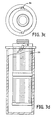
- FIG. 7 a is a cross sectional view of an alternative bowl construction of this invention.
- FIG. 7 b is a partial top view of the bowl of FIG. 7 a.
- FIG. 7 c is a cross sectional view of a filter cartridge of this invention being positioned into the bowl of FIG. 7 a.
- FIG. 7 d is a cross sectional view of the filter cartridge of FIG. 7 c fully positioned into the bowl of FIG. 7 a.
- FIG. 7 e is a partial top view of the bowl and cartridge of FIG. 7 d.
- FIG. 8 is an isometric view of a filter cartridge of this invention having flanges that snap fit into a bowl.
- FIG. 9 a is a partial isometric view of an inner surface of a bowl into which fits the filter cartridge of FIG. 9 a.
- FIG. 9 b is a partial isometric view of an inner surface of a bowl into which fits the filter cartridge of FIG. 9 a.
- FIG. 9 c is a side view of the cartridge of FIG. 9 a fit into the bowl of FIG. 9 b.
- FIG. 9 d is a top view of the construction of FIG. 9 c.
- FIG. 9 e is a side view illustrating the separation of the filter cartridge from the bowl of FIG. 9 c.
- FIG. 9 f is a top view of the construction of FIG. 9 e.
- FIG. 9 b illustrates a means for separating the filter cartridge of FIG. 9 a from the bowl.
- FIG. 11 is a cross sectional view of the collar of fin. 10 positioned about a filter cartridge.
- FIG. 12 is a top two of the collar of FIG. 10 when opened.
- FIG. 13 is a top view of a collar positioned about a filter cartridge.
- FIG. 14 is a partial isometric view of a filter cartridge having a partial collar.
- FIG. 15 is a partial side view of the collar of FIG. 14 .
- FIG. 16 is an exploded cross sectional view of a filtration module of this invention.
- FIG. 17 illustrates the tightening of the filter cartridge of FIG. 5 .
- FIG. 18 is a cross sectional view showing the filtration module of FIG. 17 .
- FIG. 19 is a cross sectional view illustrating the removal of the filtration cartridge from a manifold.
- FIG. 20 is a cross sectional view showing the alignment fins in the bowl.
- FIG. 21 is planar view of another embodiment of the present invention.
- FIG. 22 is a cross sectional view showing the filtration module of FIG. 21 .
- FIG. 24 is a planar view of an additional embodiment of the present invention.
- FIG. 25 is a planar view of an additional embodiment of the present invention.
- FIG. 25 a is a planar, top down view of a further embodiment of the present invention and FIG. 25 b;
- the present invention provides a filtration module formed of a manifold, a filtration cartridge and a bowl.
- the manifold provides fluid pathways for fluid feed into the filtration cartridge and permeate removal from the filtration cartridge.
- the bowl provides a means of storing fluid feed to permit its introduction into the filtration cartridge or to store permeate from the filtration cartridge to be directed to the manifold and then from the filtration module.
- Fluid feed can be introduced into the filtration cartridge through the manifold either from the outside of the filtration cartridge or from within the interior of the filtration cartridge.
- the fluid in the bowl adjacent the filtration cartridge can be either fluid feed or permeate. In any event, the fluid feed is introduced from a manifold into the filtration module and permeate is removed from the filtration module from the manifold.
- the filtration module and bowl are constructed so that they are sealed with the manifold or removed from contact with the manifold as one piece.
- the bowl and filtration module can be formed as one piece or can be formed from two pieces which are interlocked together by moving the bowl and filter cartridge in only one direction relative to each other at a given time. After the bowl and filtration module have been connected to the manifold, they are locked together so that, during use in filtering of fluid, they do not become separated.
- the bowl and filtration module are removed from the manifold as a single piece rather than as two separate pieces. Since the bowl and filtration module are removed together, the filtration module need not be removed form the bowl. Thus, a space substantially equal to the length of the filtration module and the bowl together need not be provided. Only a space as long as substantially the length of the bowl need be provided. This permits one to install a filtration module of this invention within a smaller space as compared to the space required with present filtration modules. In addition, since the filtration module is removed with the bowl, it need not be handled by a worker either by hand or with a hand tool. Furthermore, any fluid positioned between the bowl and the filtration module upon completion of filtration need not be removed. This substantially reduces the possibility of contacting fluid within the bowl with a worker. Alternatively, the bowl could contain a drain for removing fluid before removal.
- the manifold 10 includes an inlet 12 , external threads 13 for connecting the bowl and an outlet 14 .
- Fluid passageway 16 permits introduction of feed fluid into a bowl (not shown) to the outlet 14 .
- the filter cartridge 26 having an outlet 32 also has flanges 35 from which extend lugs 36 .
- the lugs as shown in the Figures are oval or ellipsoid in shape, although they can be of any shape suitable for securing the cartridge to the bowl, including circular or polygonal such as square or octogonal.
- the lugs 36 fit into slots 37 of bowl 39 , the slots 37 are provided with a shoulder 38 .
- the lugs 36 are positioned into slots 37 .
- FIGS. 3 c and 3 d the lugs 36 are positioned into slots 37 .
- the lugs are moved within slots until they contact shoulders 38 .
- the cartridge 26 is in a position where it is not centered within bowl 39 when the lugs 36 contact shoulder 38 .
- the lugs 36 are positioned at the ends 41 of slot 37 by rotating cartridge 26 so that it is substantially centered within bowl 39 .
- the lugs 36 are snap fit between ends 41 and shoulder 38 . While a snap fit is preferred to ensure a good retention, simple interference fitting may also be used.
- the filtration cartridge 26 is positioned within bowl 28 .
- the filtration cartridge 26 includes a cartridge such as a pleated cartridge 27 surrounded by supporting ribs 29 . However as the filtration cartridge 26 is sealed within the bowl 28 , one may use a cartridge which has no cage as the bowl 28 itself provides the protection of the filtration cartridge 26 during use and handling.
- the bowl 28 includes a plurality of fluid inlets 30 through which a fluid feed is introduced into bowl 28 .
- the bowl 28 is provided with an outlet 32 through which permeate is recovered from the filtration cartridge 26 .
- the fluid flow can be reversed whereby fluid feed is introduced through outlet (now inlet) 32 and permeate is removed through inlet (now outlet) 30 .
- the filtration cartridge 26 and bowl 28 can be joined together to form a single piece by any conventional means such as by molding or by the use of adhesive, thermal bonding, acoustic bonding or the like.
- the filter cartridge-bowl construction of FIG. 4 which includes a means for securing the cartridge-bowl construction to a manifold (not shown) wherein the construction includes the bowl 28 and the filter cartridge 26 .
- the outer flange 40 of the bowl 28 is supported by the inner flange 42 of the rotatable ring 34 .
- the ring 34 includes threads 35 on its inner surface which mate with threads 13 on the manifold of FIG. 1 or 2 .
- the ring 34 is supported about bowl 28 by rods 36 that are formed integrally with the bowl 28 such as by being molded thereto.
- the ring 34 By virtue of the ring 34 being supported by the rods 36 , it is free to rotate in either the clockwise direction or in the counterclockwise direction.
- the outlet 32 having O rings 33 thereon is raised to become sealed within outlet 15 of manifold 10 or 11 ( FIG. 1 or 2 ).
- the arrangement and number of O rings used is not critical to the invention and varies from maker to maker and application to application. Since the bowl 28 and filter cartridge 26 are formed integrally, the bowl 28 and cartridge 26 are raised or lowered as a single unit when the ring 34 is rotated with respect to the manifold 10 or 11 .
- the bowl 28 and filter cartridge 26 need not be moved relative to each other to position the filter construction of this invention in place or to remove the bowl 28 and filter cartridge 26 from the manifold 10 or 11 ( FIGS. 1 and 2 ).
- the length of space to assemble or disassemble the filter construction of this invention is the length of the outlet 32 rather than the entire length of the bowl 28 or the cartridge 26 .
- the bowl 28 includes the ring 34 and internal threads 35 .
- the bowl 28 also includes slots 40 .
- the flanges 70 of filter cartridge 68 fit into slots 40 so that the flanges are snap fit to be positioned within slots 40 . This positioning of the filter cartridge locks it into position and permits the cartridge 68 to be moved as a unit with the bowl 28 away from or in sealing contact with a manifold (not shown).
- the bowl 41 includes, on its inner surface 43 two spaced apart flanges 45 and a third flange 47 having a notch 49 .
- a filter cartridge 51 having a flange 53 is first positioned so that flange 53 is positioned between flange 47 and flanges 45 ( FIG. 7 c ). The cartridge 51 then is slid into the position shown in FIG. 7 d so that flange 53 having shoulder 55 is positioned so that shoulder 55 fits into notch 49 thereby retaining cartridge 51 on bowl 41 .
- two sets of the flanges shown are positioned about 180 degrees apart on the inside surface 43 of the bowl 42 . Since the shoulder 55 is slightly larger than the slight extensions 60 surrounding the notch 49 , the shoulder 55 is held in place within notch 49 by friction. Thus, the shoulder 55 is snap fit in notch 49 .
- the top portion 57 of filter cartridge 59 having fluid outlet or inlet 61 includes arms 65 which are snap fit into slots 67 within the inner surface periphery of a bowl 69 . After the arms 65 are snap fit into the slots 67 , the bowl 69 and filter cartridge 59 can be sealed into a manifold (not shown) as a single unit.
- the flange 65 is provided with a wedge shaped element 70 secured to surface 71 and spaced apart from surface 72 . When separation of the bowl 69 from the cartridge 59 is desired, a hand held tool can be slid along surface 70 a and under wedge 70 to bend flange 65 away from slot to effect removal therefrom.
- a collar 80 is illustrated which is utilized in conjunction with a filter cartridge free of a flange which can be snap fit into a slot of a bowl as discussed above.
- the collar 80 provides the advantage that it can be removed from a used filter cartridge prior to discarding the used cartridge so that the collar 80 can be reused with a fresh filter cartridge.
- the collar 80 is provided with feed inlets 82 to the bowl 28 ( FIG. 6 ).
- the collar 80 attaches to a flange 86 of a filter cartridge 84 .
- the collar 80 is provided with flanges 88 that are fit into slots of a bowl as described above.
- the design of the flanges can be of any design provided they produce the desired retention function.
- the collar 80 includes a hinge 81 so that a portion of it can be rotated to engage hook elements 83 and 85 to engage or disengage the collar 80 with or from the filter cartridge 84 . Permeate is removed from the filter cartridge through outlet 81 .
- FIGS. 13 , 14 and 15 an alternative collar construction is shown that includes two hinges 90 and 91 as well as mating hooks 92 and 93 .
- the collar fits about the periphery of filter cartridge 94 which includes a permeate outlet 95 .
- the flanges 96 fit into mating slots of a bowl as described above with reference to FIG. 6 .
- FIGS. 17 , 18 and 19 illustrate the installation and removal of the filtration module of this invention shown in with respect to the filter cartridge-bowl construction shown in FIG. 5 .
- the threads 38 of ring 34 are contacted with the threads 13 of manifold 37 .
- the ring 34 then is rotated counterclockwise as illustrated by arrow 39 moves the filter cartridge 96 and bowl 28 toward the manifold 37 until the filter cartridge 26 and bowl 28 are in the position relative to the manifold 37 shown in FIG. 18 .
- This relative movement is achieved by virtue of rotation of the ring 34 and because the ring 34 is supported by the rods 36 .
- the filter cartridge 26 and bowl 28 move as a unit since the filter cartridge is locked into bowl 28 as described above with reference to FIG.
- One or more alignment fins 200 are formed on the lower inner surface 201 of the bowl 202 . Those fins allow the cartridge 203 to be trued in a vertical alignment as it is placed into the bowl 202 .
- the number of fins 200 used preferably is at least from 2 to 6 with 3 being the most preferred.
- the fins 200 preferably are equally spaced from each other around the circumference of the inner surface 201 .
- the fins 200 are of a stepped configuration with the upper portion being on angle less than that of vertical and the lower portion being substantially vertical in orientation. This preferred embodiment allows for the cartridge 203 to be easily inserted into the housing and rest adjacent the bottom of the housing. If desired, other arrangements of fins as to angle, length, height may be used and are not critical to the invention so long as they provide adequate mounting and demounting of the cartridge from the housing.
- the collar feature of the present invention as shown in FIGS. 10-12 may be comprised of a collar that contains no hinges. Such an embodiment is shown in FIG. 21 .
- the collar 210 is simply snap-fit over the end of the cartridge portion 211 to which it is attached and held in place to the cartridge by the snap-fit design.
- the design of this embodiment or the embodiment of FIGS. 10-12 may use the flange as shown in FIGS. 10-12 or it may use a bayonet or lug 212 as shown in FIG. 21 as the means for attaching the cartridge to the housing
- the selection of the attachment means is not critical to the invention.
- FIG. 22 shows the embodiment of FIG. 21 in cross section as attached to the cartridge.
- the attachment devices used to secure the cartridge to the housing may be mounted to any portion of the cartridge.
- the flanges and attachment devices are mounted to the end cap of the cartridge.
- the attachment devices 220 may be formed on the body of the cartridge 221 itself such as the sleeve portion 222 of FIG. 24 or the attachment devices 231 may be formed on or attached to the cartridge adaptor 230 of FIGS. 25 a and 25 b.
- This media may be formed of any material typically used in filtration such as paper, other cellulosic materials such as regenerated cellulose or nitrocellulose, glass fiber and fabric, metal such as stainless steel, nickel, chromium and alloys and blends thereof, ceramics, plastics, preferably thermoplastic materials such as polyolefins, homopolymers, copolymers or terpolymers, including polyethylene such as ultrahigh molecular weight polyethylene, polypropylene and the like, PVDF, PTFE resin, PFA, ECTFE and other fluorinated resins, particularly perfluorinated thermoplastic resins, PVC, nylons, polyamides, polysulphones, modified polysulphones such as polyethersulphones, polyarylsulphones and polyphenylsulphones, polyimides, polycarbonates, PET and the like.
- thermoplastic materials such as polyolefins, homopolymers, copolymers or terpolymers, including polyethylene such as ultrahigh molecular
- the bowl and manifold may be made of a plastic, preferably a thermoplastic including polyolefins such as polyethylene, ultrahigh molecular weight polyethylene or polypropylene, copolymers or terpolymers of polyolefins, nylons, PTFE resin, PFA, PVDF, ECTFE and other fluorinated resins, particularly perfluorinated thermoplastic resins, polycarbonates, polysulphones, modified polysulphones such as polyethersulphone, polyarylsulphones or polyphenylsulphones, any glass or other reinforced plastic or a metal such as stainless steel, aluminum, copper, bronze, brass, nickel, chromium or titanium or alloys or blends thereof.
- polyolefins such as polyethylene, ultrahigh molecular weight polyethylene or polypropylene, copolymers or terpolymers of polyolefins, nylons, PTFE resin, PFA, PVDF, ECTFE and other fluorinated resins, particularly per
Landscapes
- Chemical & Material Sciences (AREA)
- Chemical Kinetics & Catalysis (AREA)
- Separation Using Semi-Permeable Membranes (AREA)
Abstract
Description
Claims (9)
Priority Applications (1)
| Application Number | Priority Date | Filing Date | Title |
|---|---|---|---|
| US12/215,539 US8070945B2 (en) | 1998-10-09 | 2008-06-27 | Filtration module including unitary filter cartridge-bowl construction |
Applications Claiming Priority (6)
| Application Number | Priority Date | Filing Date | Title |
|---|---|---|---|
| US10364698P | 1998-10-09 | 1998-10-09 | |
| PCT/US1999/022347 WO2000021640A1 (en) | 1998-10-09 | 1999-09-28 | Filtration module including unitary filter cartridge-bowl construction |
| US10/019,836 US6533933B1 (en) | 1998-10-09 | 1999-09-28 | Filtration module including unitary filter cartridge-bowl construction |
| US10/246,248 US20030141235A1 (en) | 2001-10-22 | 2002-09-18 | Filtration module including unitary filter cartridge-bowl construction |
| US10/956,892 US7445710B2 (en) | 1998-10-09 | 2004-09-30 | Filtration module including unitary filter cartridge-bowl construction |
| US12/215,539 US8070945B2 (en) | 1998-10-09 | 2008-06-27 | Filtration module including unitary filter cartridge-bowl construction |
Related Parent Applications (1)
| Application Number | Title | Priority Date | Filing Date |
|---|---|---|---|
| US10/956,892 Continuation US7445710B2 (en) | 1998-10-09 | 2004-09-30 | Filtration module including unitary filter cartridge-bowl construction |
Publications (2)
| Publication Number | Publication Date |
|---|---|
| US20090184043A1 US20090184043A1 (en) | 2009-07-23 |
| US8070945B2 true US8070945B2 (en) | 2011-12-06 |
Family
ID=34198797
Family Applications (2)
| Application Number | Title | Priority Date | Filing Date |
|---|---|---|---|
| US10/956,892 Expired - Lifetime US7445710B2 (en) | 1998-10-09 | 2004-09-30 | Filtration module including unitary filter cartridge-bowl construction |
| US12/215,539 Expired - Fee Related US8070945B2 (en) | 1998-10-09 | 2008-06-27 | Filtration module including unitary filter cartridge-bowl construction |
Family Applications Before (1)
| Application Number | Title | Priority Date | Filing Date |
|---|---|---|---|
| US10/956,892 Expired - Lifetime US7445710B2 (en) | 1998-10-09 | 2004-09-30 | Filtration module including unitary filter cartridge-bowl construction |
Country Status (1)
| Country | Link |
|---|---|
| US (2) | US7445710B2 (en) |
Cited By (11)
| Publication number | Priority date | Publication date | Assignee | Title |
|---|---|---|---|---|
| US20140041346A1 (en) * | 2011-04-20 | 2014-02-13 | Ufi Innovation Center S.R.L. | Filter group |
| US20140224725A1 (en) * | 2013-02-08 | 2014-08-14 | Tea Spot, Inc. | Cold infusion device for water bottles |
| USD717395S1 (en) * | 2012-10-29 | 2014-11-11 | Parker Hannifin Industria E Comercio Ltda. | Filter element cap |
| USD726869S1 (en) * | 2013-06-25 | 2015-04-14 | Baldwin Filters, Inc. | Filter element |
| US9089805B2 (en) | 2013-06-25 | 2015-07-28 | Baldwin Filters, Inc. | Air filter and inlet tube assembly |
| US9937451B2 (en) | 2011-09-15 | 2018-04-10 | Whirlpool Corporation | Filter unit |
| US10010820B1 (en) | 2011-09-15 | 2018-07-03 | Whirlpool Corporation | Water filter system |
| US20180243669A1 (en) * | 2015-09-23 | 2018-08-30 | Volvo Truck Corporation | A filter insert and a filter arrangement |
| US10525387B2 (en) | 2017-04-06 | 2020-01-07 | Whirlpool Corporation | Filter cartridge |
| US10584040B2 (en) | 2017-10-06 | 2020-03-10 | Whirlpool Corporation | Filter cartridge |
| US10807025B2 (en) | 2018-08-06 | 2020-10-20 | Whirlpool Corporation | Blind attachment interface for filter housing assembly |
Families Citing this family (25)
| Publication number | Priority date | Publication date | Assignee | Title |
|---|---|---|---|---|
| DE202005007870U1 (en) * | 2005-05-13 | 2006-09-21 | Mann + Hummel Gmbh | Filter device, in particular for liquid filtration in internal combustion engines |
| GB0715247D0 (en) * | 2007-08-04 | 2007-09-12 | Parker Hannifin Ltd | Filter assembly |
| GB0715269D0 (en) * | 2007-08-04 | 2007-09-12 | Parker Hannifin Ltd | Filter assembly |
| US20090200222A1 (en) * | 2008-02-08 | 2009-08-13 | Dellemonache Mauro G | System and method for filter containment |
| KR20100081827A (en) * | 2009-01-07 | 2010-07-15 | 삼성전자주식회사 | Water filter assembly and valve assembly and water purifier having the same |
| DE102010005390A1 (en) * | 2010-01-22 | 2011-07-28 | MAHLE International GmbH, 70376 | filtering device |
| USD654564S1 (en) | 2011-09-15 | 2012-02-21 | Whirlpool Corporation | Filter unit |
| USD654561S1 (en) | 2011-09-15 | 2012-02-21 | Whirlpool Corporation | Filter unit |
| USD654560S1 (en) | 2011-09-15 | 2012-02-21 | Whirlpool Corporation | Filter unit |
| USD654562S1 (en) | 2011-09-15 | 2012-02-21 | Whirlpool Corporation | Filter unit |
| US8580109B2 (en) | 2011-09-15 | 2013-11-12 | Whirlpool Corporation | Electronic interface for water filter system |
| USD654559S1 (en) | 2011-09-15 | 2012-02-21 | Whirlpool Corporation | Filter unit |
| USD654563S1 (en) | 2011-09-15 | 2012-02-21 | Whirlpool Corporation | Filter unit |
| US8413818B1 (en) | 2011-09-15 | 2013-04-09 | Whirlpool Corporation | Filter unit |
| USD655377S1 (en) | 2011-09-15 | 2012-03-06 | Whirlpool Corporation | Filter unit |
| USD655378S1 (en) | 2011-09-15 | 2012-03-06 | Whirlpool Corporation | Filter unit |
| US8950052B2 (en) | 2011-09-15 | 2015-02-10 | Whirlpool Corporation | Method of installing a filter unit |
| US8591736B2 (en) | 2011-09-15 | 2013-11-26 | Whirlpool Corporation | Water filter unit |
| USD654565S1 (en) | 2011-09-15 | 2012-02-21 | Whirlpool Corporation | Filter unit |
| USD654566S1 (en) | 2011-09-15 | 2012-02-21 | Whirlpool Corporation | Filter unit |
| CN109562324B (en) * | 2016-06-27 | 2022-04-26 | 恩特格里斯公司 | High retention polyamide hollow fiber membranes made via controlled shrinkage |
| JP2020157236A (en) * | 2019-03-27 | 2020-10-01 | 三菱日立パワーシステムズ株式会社 | Metal filter and method for producing the same |
| KR20220015825A (en) | 2020-07-31 | 2022-02-08 | 코웨이 주식회사 | Filter frame and air clearner including the same |
| CN113332814A (en) * | 2021-06-02 | 2021-09-03 | 张婕 | Garbage combustion flue gas purification device |
| EP4426463A4 (en) * | 2021-11-04 | 2025-09-03 | Entegris Inc | FILTER CARTRIDGE ASSEMBLY |
Citations (49)
| Publication number | Priority date | Publication date | Assignee | Title |
|---|---|---|---|---|
| US2955712A (en) * | 1958-05-08 | 1960-10-11 | Parmatic Engineering Ltd | High pressure oil filter unit having threaded bowl assembly valve actuating means |
| US2991885A (en) * | 1957-07-15 | 1961-07-11 | New York Business Dev Corp | Oil filter unit |
| US3118836A (en) | 1960-06-23 | 1964-01-21 | Southwick W Briggs | Filter |
| US3399776A (en) | 1965-09-02 | 1968-09-03 | Robert R. Knuth | Detachable snap-on filter for a hydraulic system |
| US3696933A (en) | 1970-06-15 | 1972-10-10 | Pall Corp | Inertia filter |
| SU528108A1 (en) | 1975-06-23 | 1976-09-15 | Предприятие П/Я Г-4371 | Hydraulic filter |
| US4028254A (en) | 1975-10-14 | 1977-06-07 | Nupro Company | Fluid filter |
| SU583810A1 (en) | 1975-06-16 | 1977-12-15 | Предприятие П/Я Г-4371 | Hydraulic filter |
| SU605626A1 (en) | 1976-09-06 | 1978-05-05 | Предприятие П/Я Г-4371 | Filter for high-pressure hydraulic systems |
| US4172798A (en) | 1977-02-28 | 1979-10-30 | Ultrafilter Gmbh | Filter housing |
| SU755291A1 (en) | 1978-06-27 | 1980-08-15 | Anatolij A Rogovskij | HYDRAULIC FILTER 1 2 |
| US4316801A (en) | 1980-07-22 | 1982-02-23 | Pall Corporation | Filter assembly with jacked filter cannister |
| US4645601A (en) | 1984-08-31 | 1987-02-24 | Everpure, Inc. | Quick change reverse osmosis assembly |
| US4678576A (en) | 1981-09-16 | 1987-07-07 | Nalge Company | Reusable filter unit with recoverable filter membrane |
| US4719012A (en) | 1986-05-30 | 1988-01-12 | Caterpillar Inc. | Twist on disposable filter |
| US4735716A (en) | 1986-01-27 | 1988-04-05 | Cuno Corporated | Quick-change filter cartridge and head therefor |
| US4876005A (en) | 1988-02-12 | 1989-10-24 | The Perkin-Elmer Corporation | High pressure column assembly for a liquid chromatograph system |
| EP0364299A2 (en) | 1988-10-13 | 1990-04-18 | Everpure, Inc. | Filtering system |
| US4948505A (en) | 1986-01-27 | 1990-08-14 | Cuno, Inc. | Quick-change filter cartridge and head therefor |
| US5035797A (en) | 1990-02-14 | 1991-07-30 | Stanadyne Automotive Corp. | Key system for filter assembly |
| US5089131A (en) | 1988-11-08 | 1992-02-18 | Halliburton Company | Corrosion resistant filter unit |
| US5114572A (en) | 1988-09-09 | 1992-05-19 | Process Scientific Innovations Limited | Filter assembly and cartridge therefor |
| US5133858A (en) | 1989-11-30 | 1992-07-28 | Layton Manufacturing Corporation | Reverse osmosis water purification apparatus |
| US5354464A (en) | 1990-03-14 | 1994-10-11 | Water Factory Systems | Multi-port connecting device |
| EP0657201A2 (en) | 1993-12-13 | 1995-06-14 | Stanadyne Automotive Corp. | Module for filter assembly base |
| GB2290486A (en) | 1994-06-27 | 1996-01-03 | Pall Corp | Filter assemblies |
| US5549821A (en) | 1993-09-29 | 1996-08-27 | Fleetguard, Inc. | Fluid filter assembly for vehicles |
| US5548893A (en) | 1995-03-20 | 1996-08-27 | Koelfgen; Douglas F. | Spin-on oil filter replacement element |
| US5556542A (en) | 1993-09-29 | 1996-09-17 | Fleetguard, Inc. | Fluid filter assembly |
| DE19623681A1 (en) | 1995-06-17 | 1996-12-19 | Knecht Filterwerke Gmbh | Lubricating oil filter for ic. engines |
| US5591329A (en) | 1995-05-31 | 1997-01-07 | H-Tech, Inc. | Fluid filter with pleated septum |
| US5595651A (en) | 1995-01-23 | 1997-01-21 | Pavel; Augustin | All-plastic hand-assembled super-strength reverse osmosis membrane housing |
| US5601711A (en) | 1994-10-31 | 1997-02-11 | Gelman Sciences Inc. | Selective separation filter device |
| US5609757A (en) | 1994-02-08 | 1997-03-11 | Hytec Flow Systems | Housing assembly for the filtration of corrosive liquids and a method for temporary sealing of a housing assembly |
| WO1997047891A1 (en) | 1996-06-12 | 1997-12-18 | Knecht Filterwerke Gmbh | Snap-lock connection for two parts which can rotate in relation to each other |
| US5753107A (en) | 1996-08-08 | 1998-05-19 | Wtc Ecomaster Corporation | Dripless purification manifold and cartridge |
| US5770054A (en) | 1995-03-16 | 1998-06-23 | Firma Ing. Walter Hengst Gmbh & Co. Kg | Fluid filter with filter bypass valve and sealing surface on filter element side |
| US5837137A (en) | 1996-08-21 | 1998-11-17 | Stanadyne Automotive Corp. | Base/cartridge location and key system for fuel filter assembly |
| US5891334A (en) * | 1997-06-19 | 1999-04-06 | Plymouth Products, Inc. | Filter cartridge retaining assembly |
| US5956822A (en) | 1996-06-12 | 1999-09-28 | Knecht Filterwerke Gmbh | Snap-lock connection for two parts which can rotate in relation to each other |
| US6006924A (en) | 1997-05-14 | 1999-12-28 | Pti Technologies, Inc. | Multi-media filtration system with reusable and demountable filter cartridge |
| WO2000021640A1 (en) | 1998-10-09 | 2000-04-20 | Millipore Corporation | Filtration module including unitary filter cartridge-bowl construction |
| WO2001026777A1 (en) | 1999-10-14 | 2001-04-19 | Millipore Corporation | Filter housing |
| US20020014452A1 (en) | 2000-02-16 | 2002-02-07 | Janik Leon P. | Ecological fuel filter cartridge and element |
| US20020046969A1 (en) | 2000-06-14 | 2002-04-25 | The Procter & Gamble Company | Spraying device |
| WO2003002229A1 (en) | 2001-06-28 | 2003-01-09 | Mykrolis Corporation | Filtration module including unitary filter cartridge-bowl construction |
| WO2003002228A1 (en) | 2001-06-28 | 2003-01-09 | Mykrolis Corporation | Filtration module including unitary filter cartridge-bowl construction |
| WO2003082435A1 (en) | 2002-03-28 | 2003-10-09 | Mykrolis Corporation | Filter cartridge construction |
| WO2003082434A1 (en) | 2002-03-28 | 2003-10-09 | Mykrolis Corporation | Filter cartridge construction |
Family Cites Families (3)
| Publication number | Priority date | Publication date | Assignee | Title |
|---|---|---|---|---|
| US14452A (en) * | 1856-03-18 | Etui-machine | ||
| US46969A (en) * | 1865-03-21 | Improved cane-juice evaporator | ||
| US5679251A (en) | 1995-07-24 | 1997-10-21 | The Oilguard Company, Llc | Wound oil filter |
-
2004
- 2004-09-30 US US10/956,892 patent/US7445710B2/en not_active Expired - Lifetime
-
2008
- 2008-06-27 US US12/215,539 patent/US8070945B2/en not_active Expired - Fee Related
Patent Citations (52)
| Publication number | Priority date | Publication date | Assignee | Title |
|---|---|---|---|---|
| US2991885A (en) * | 1957-07-15 | 1961-07-11 | New York Business Dev Corp | Oil filter unit |
| US2955712A (en) * | 1958-05-08 | 1960-10-11 | Parmatic Engineering Ltd | High pressure oil filter unit having threaded bowl assembly valve actuating means |
| US3118836A (en) | 1960-06-23 | 1964-01-21 | Southwick W Briggs | Filter |
| US3399776A (en) | 1965-09-02 | 1968-09-03 | Robert R. Knuth | Detachable snap-on filter for a hydraulic system |
| US3696933A (en) | 1970-06-15 | 1972-10-10 | Pall Corp | Inertia filter |
| SU583810A1 (en) | 1975-06-16 | 1977-12-15 | Предприятие П/Я Г-4371 | Hydraulic filter |
| SU528108A1 (en) | 1975-06-23 | 1976-09-15 | Предприятие П/Я Г-4371 | Hydraulic filter |
| US4028254A (en) | 1975-10-14 | 1977-06-07 | Nupro Company | Fluid filter |
| SU605626A1 (en) | 1976-09-06 | 1978-05-05 | Предприятие П/Я Г-4371 | Filter for high-pressure hydraulic systems |
| US4172798A (en) | 1977-02-28 | 1979-10-30 | Ultrafilter Gmbh | Filter housing |
| SU755291A1 (en) | 1978-06-27 | 1980-08-15 | Anatolij A Rogovskij | HYDRAULIC FILTER 1 2 |
| US4316801A (en) | 1980-07-22 | 1982-02-23 | Pall Corporation | Filter assembly with jacked filter cannister |
| US4678576A (en) | 1981-09-16 | 1987-07-07 | Nalge Company | Reusable filter unit with recoverable filter membrane |
| US4645601A (en) | 1984-08-31 | 1987-02-24 | Everpure, Inc. | Quick change reverse osmosis assembly |
| US4948505A (en) | 1986-01-27 | 1990-08-14 | Cuno, Inc. | Quick-change filter cartridge and head therefor |
| US4735716A (en) | 1986-01-27 | 1988-04-05 | Cuno Corporated | Quick-change filter cartridge and head therefor |
| US4719012A (en) | 1986-05-30 | 1988-01-12 | Caterpillar Inc. | Twist on disposable filter |
| US4876005A (en) | 1988-02-12 | 1989-10-24 | The Perkin-Elmer Corporation | High pressure column assembly for a liquid chromatograph system |
| US5114572A (en) | 1988-09-09 | 1992-05-19 | Process Scientific Innovations Limited | Filter assembly and cartridge therefor |
| EP0364299A2 (en) | 1988-10-13 | 1990-04-18 | Everpure, Inc. | Filtering system |
| US5089131A (en) | 1988-11-08 | 1992-02-18 | Halliburton Company | Corrosion resistant filter unit |
| US5133858A (en) | 1989-11-30 | 1992-07-28 | Layton Manufacturing Corporation | Reverse osmosis water purification apparatus |
| US5035797A (en) | 1990-02-14 | 1991-07-30 | Stanadyne Automotive Corp. | Key system for filter assembly |
| US5354464A (en) | 1990-03-14 | 1994-10-11 | Water Factory Systems | Multi-port connecting device |
| US5556542A (en) | 1993-09-29 | 1996-09-17 | Fleetguard, Inc. | Fluid filter assembly |
| US5549821A (en) | 1993-09-29 | 1996-08-27 | Fleetguard, Inc. | Fluid filter assembly for vehicles |
| EP0657201A2 (en) | 1993-12-13 | 1995-06-14 | Stanadyne Automotive Corp. | Module for filter assembly base |
| US5609757A (en) | 1994-02-08 | 1997-03-11 | Hytec Flow Systems | Housing assembly for the filtration of corrosive liquids and a method for temporary sealing of a housing assembly |
| GB2290486A (en) | 1994-06-27 | 1996-01-03 | Pall Corp | Filter assemblies |
| US5601711A (en) | 1994-10-31 | 1997-02-11 | Gelman Sciences Inc. | Selective separation filter device |
| US5595651A (en) | 1995-01-23 | 1997-01-21 | Pavel; Augustin | All-plastic hand-assembled super-strength reverse osmosis membrane housing |
| US5770054A (en) | 1995-03-16 | 1998-06-23 | Firma Ing. Walter Hengst Gmbh & Co. Kg | Fluid filter with filter bypass valve and sealing surface on filter element side |
| US5548893A (en) | 1995-03-20 | 1996-08-27 | Koelfgen; Douglas F. | Spin-on oil filter replacement element |
| US5591329A (en) | 1995-05-31 | 1997-01-07 | H-Tech, Inc. | Fluid filter with pleated septum |
| US5814215A (en) | 1995-06-17 | 1998-09-29 | Knecht Filterwerke Gmbh | Oil filter including an integral filter support and housing drain valve assembly |
| DE19623681A1 (en) | 1995-06-17 | 1996-12-19 | Knecht Filterwerke Gmbh | Lubricating oil filter for ic. engines |
| WO1997047891A1 (en) | 1996-06-12 | 1997-12-18 | Knecht Filterwerke Gmbh | Snap-lock connection for two parts which can rotate in relation to each other |
| US5956822A (en) | 1996-06-12 | 1999-09-28 | Knecht Filterwerke Gmbh | Snap-lock connection for two parts which can rotate in relation to each other |
| US5753107A (en) | 1996-08-08 | 1998-05-19 | Wtc Ecomaster Corporation | Dripless purification manifold and cartridge |
| US5837137A (en) | 1996-08-21 | 1998-11-17 | Stanadyne Automotive Corp. | Base/cartridge location and key system for fuel filter assembly |
| US6006924A (en) | 1997-05-14 | 1999-12-28 | Pti Technologies, Inc. | Multi-media filtration system with reusable and demountable filter cartridge |
| US5891334A (en) * | 1997-06-19 | 1999-04-06 | Plymouth Products, Inc. | Filter cartridge retaining assembly |
| WO2000021640A1 (en) | 1998-10-09 | 2000-04-20 | Millipore Corporation | Filtration module including unitary filter cartridge-bowl construction |
| US6533933B1 (en) | 1998-10-09 | 2003-03-18 | Mykrolis Corporation | Filtration module including unitary filter cartridge-bowl construction |
| WO2001026777A1 (en) | 1999-10-14 | 2001-04-19 | Millipore Corporation | Filter housing |
| US6635175B2 (en) | 1999-10-14 | 2003-10-21 | Mykrolis Corporation | Filter housing |
| US20020014452A1 (en) | 2000-02-16 | 2002-02-07 | Janik Leon P. | Ecological fuel filter cartridge and element |
| US20020046969A1 (en) | 2000-06-14 | 2002-04-25 | The Procter & Gamble Company | Spraying device |
| WO2003002229A1 (en) | 2001-06-28 | 2003-01-09 | Mykrolis Corporation | Filtration module including unitary filter cartridge-bowl construction |
| WO2003002228A1 (en) | 2001-06-28 | 2003-01-09 | Mykrolis Corporation | Filtration module including unitary filter cartridge-bowl construction |
| WO2003082435A1 (en) | 2002-03-28 | 2003-10-09 | Mykrolis Corporation | Filter cartridge construction |
| WO2003082434A1 (en) | 2002-03-28 | 2003-10-09 | Mykrolis Corporation | Filter cartridge construction |
Cited By (20)
| Publication number | Priority date | Publication date | Assignee | Title |
|---|---|---|---|---|
| US9314724B2 (en) * | 2011-04-20 | 2016-04-19 | Ufi Innovation Center S.R.L. | Filter group |
| US20140041346A1 (en) * | 2011-04-20 | 2014-02-13 | Ufi Innovation Center S.R.L. | Filter group |
| US9604171B2 (en) * | 2011-04-20 | 2017-03-28 | Ufi Innovation Center S.R.L. | Filter group |
| US10022658B2 (en) | 2011-09-15 | 2018-07-17 | Whirlpool Corporation | Water filter system |
| US9937451B2 (en) | 2011-09-15 | 2018-04-10 | Whirlpool Corporation | Filter unit |
| US10010820B1 (en) | 2011-09-15 | 2018-07-03 | Whirlpool Corporation | Water filter system |
| US10653985B2 (en) | 2011-09-15 | 2020-05-19 | Whirlpool Corporation | Water filter system |
| US11291937B2 (en) | 2011-09-15 | 2022-04-05 | Whirlpool Corporation | Water filter system |
| US11247156B2 (en) | 2011-09-15 | 2022-02-15 | Whirlpool Corporation | Water filter system |
| USD717395S1 (en) * | 2012-10-29 | 2014-11-11 | Parker Hannifin Industria E Comercio Ltda. | Filter element cap |
| US20140224725A1 (en) * | 2013-02-08 | 2014-08-14 | Tea Spot, Inc. | Cold infusion device for water bottles |
| US9089805B2 (en) | 2013-06-25 | 2015-07-28 | Baldwin Filters, Inc. | Air filter and inlet tube assembly |
| USD726869S1 (en) * | 2013-06-25 | 2015-04-14 | Baldwin Filters, Inc. | Filter element |
| US20180243669A1 (en) * | 2015-09-23 | 2018-08-30 | Volvo Truck Corporation | A filter insert and a filter arrangement |
| US11247152B2 (en) * | 2015-09-23 | 2022-02-15 | Volvo Truck Corporation | Filter insert and a filter arrangement |
| US10967313B2 (en) | 2017-04-06 | 2021-04-06 | Whirlpool Corporation | Filter cartridge |
| US10525387B2 (en) | 2017-04-06 | 2020-01-07 | Whirlpool Corporation | Filter cartridge |
| US10584040B2 (en) | 2017-10-06 | 2020-03-10 | Whirlpool Corporation | Filter cartridge |
| US10807025B2 (en) | 2018-08-06 | 2020-10-20 | Whirlpool Corporation | Blind attachment interface for filter housing assembly |
| US11691098B2 (en) | 2018-08-06 | 2023-07-04 | Whirlpool Corporation | Blind attachment interface for filter housing assembly |
Also Published As
| Publication number | Publication date |
|---|---|
| US7445710B2 (en) | 2008-11-04 |
| US20090184043A1 (en) | 2009-07-23 |
| US20050040095A1 (en) | 2005-02-24 |
Similar Documents
| Publication | Publication Date | Title |
|---|---|---|
| US8070945B2 (en) | Filtration module including unitary filter cartridge-bowl construction | |
| US6533933B1 (en) | Filtration module including unitary filter cartridge-bowl construction | |
| US6635175B2 (en) | Filter housing | |
| US7101479B2 (en) | Filter cartridge construction | |
| US20040182777A1 (en) | Filtration module including unitary filter cartridge-bowl construction | |
| US7169302B2 (en) | Filter cartridge construction | |
| US20030141235A1 (en) | Filtration module including unitary filter cartridge-bowl construction | |
| US20040159600A1 (en) | Filtration module including unitary filter cartridge-bowl construction | |
| CN102814066B (en) | Filter alignment device | |
| EP1417017A1 (en) | Filtration module including unitary filter cartridge-bowl construction | |
| EP1498169B1 (en) | Filtration module | |
| WO2001002084A1 (en) | Detachable separation module | |
| JPWO2001002084A1 (en) | Detachable separation module |
Legal Events
| Date | Code | Title | Description |
|---|---|---|---|
| AS | Assignment |
Owner name: WELLS FARGO BANK, NATIONAL ASSOCIATION, AS AGENT,M Free format text: SECURITY AGREEMENT;ASSIGNOR:ENTEGRIS, INC.;REEL/FRAME:022354/0784 Effective date: 20090302 Owner name: WELLS FARGO BANK, NATIONAL ASSOCIATION, AS AGENT, Free format text: SECURITY AGREEMENT;ASSIGNOR:ENTEGRIS, INC.;REEL/FRAME:022354/0784 Effective date: 20090302 |
|
| ZAAA | Notice of allowance and fees due |
Free format text: ORIGINAL CODE: NOA |
|
| ZAAB | Notice of allowance mailed |
Free format text: ORIGINAL CODE: MN/=. |
|
| AS | Assignment |
Owner name: ENTEGRIS, INC., MASSACHUSETTS Free format text: RELEASE BY SECURED PARTY;ASSIGNOR:WELLS FARGO BANK NATIONAL ASSOCIATION;REEL/FRAME:026764/0880 Effective date: 20110609 |
|
| STCF | Information on status: patent grant |
Free format text: PATENTED CASE |
|
| AS | Assignment |
Owner name: GOLDMAN SACHS BANK USA, AS COLLATERAL AGENT, NEW YORK Free format text: SECURITY INTEREST;ASSIGNORS:ENTEGRIS, INC.;POCO GRAPHITE, INC.;ATMI, INC.;AND OTHERS;REEL/FRAME:032815/0852 Effective date: 20140430 Owner name: GOLDMAN SACHS BANK USA, AS COLLATERAL AGENT, NEW Y Free format text: SECURITY INTEREST;ASSIGNORS:ENTEGRIS, INC.;POCO GRAPHITE, INC.;ATMI, INC.;AND OTHERS;REEL/FRAME:032815/0852 Effective date: 20140430 |
|
| AS | Assignment |
Owner name: GOLDMAN SACHS BANK USA, AS COLLATERAL AGENT, NEW YORK Free format text: SECURITY INTEREST;ASSIGNORS:ENTEGRIS, INC.;POCO GRAPHITE, INC.;ATMI, INC.;AND OTHERS;REEL/FRAME:032812/0192 Effective date: 20140430 Owner name: GOLDMAN SACHS BANK USA, AS COLLATERAL AGENT, NEW Y Free format text: SECURITY INTEREST;ASSIGNORS:ENTEGRIS, INC.;POCO GRAPHITE, INC.;ATMI, INC.;AND OTHERS;REEL/FRAME:032812/0192 Effective date: 20140430 |
|
| FPAY | Fee payment |
Year of fee payment: 4 |
|
| AS | Assignment |
Owner name: POCO GRAPHITE, INC., MASSACHUSETTS Free format text: RELEASE BY SECURED PARTY;ASSIGNOR:GOLDMAN SACHS BANK USA, AS COLLATERAL AGENT;REEL/FRAME:047477/0032 Effective date: 20181106 Owner name: ADVANCED TECHNOLOGY MATERIALS, INC., CONNECTICUT Free format text: RELEASE BY SECURED PARTY;ASSIGNOR:GOLDMAN SACHS BANK USA, AS COLLATERAL AGENT;REEL/FRAME:047477/0032 Effective date: 20181106 Owner name: ENTEGRIS, INC., MASSACHUSETTS Free format text: RELEASE BY SECURED PARTY;ASSIGNOR:GOLDMAN SACHS BANK USA, AS COLLATERAL AGENT;REEL/FRAME:047477/0032 Effective date: 20181106 Owner name: ATMI PACKAGING, INC., CONNECTICUT Free format text: RELEASE BY SECURED PARTY;ASSIGNOR:GOLDMAN SACHS BANK USA, AS COLLATERAL AGENT;REEL/FRAME:047477/0032 Effective date: 20181106 Owner name: ATMI, INC., CONNECTICUT Free format text: RELEASE BY SECURED PARTY;ASSIGNOR:GOLDMAN SACHS BANK USA, AS COLLATERAL AGENT;REEL/FRAME:047477/0032 Effective date: 20181106 Owner name: ATMI PACKAGING, INC., CONNECTICUT Free format text: RELEASE BY SECURED PARTY;ASSIGNOR:GOLDMAN SACHS BANK USA, AS COLLATERAL AGENT;REEL/FRAME:047477/0151 Effective date: 20181106 Owner name: ATMI, INC., CONNECTICUT Free format text: RELEASE BY SECURED PARTY;ASSIGNOR:GOLDMAN SACHS BANK USA, AS COLLATERAL AGENT;REEL/FRAME:047477/0151 Effective date: 20181106 Owner name: POCO GRAPHITE, INC., MASSACHUSETTS Free format text: RELEASE BY SECURED PARTY;ASSIGNOR:GOLDMAN SACHS BANK USA, AS COLLATERAL AGENT;REEL/FRAME:047477/0151 Effective date: 20181106 Owner name: ADVANCED TECHNOLOGY MATERIALS, INC., CONNECTICUT Free format text: RELEASE BY SECURED PARTY;ASSIGNOR:GOLDMAN SACHS BANK USA, AS COLLATERAL AGENT;REEL/FRAME:047477/0151 Effective date: 20181106 Owner name: ENTEGRIS, INC., MASSACHUSETTS Free format text: RELEASE BY SECURED PARTY;ASSIGNOR:GOLDMAN SACHS BANK USA, AS COLLATERAL AGENT;REEL/FRAME:047477/0151 Effective date: 20181106 |
|
| AS | Assignment |
Owner name: GOLDMAN SACHS BANK USA, NEW YORK Free format text: SECURITY INTEREST;ASSIGNORS:ENTEGRIS, INC.;SAES PURE GAS, INC.;REEL/FRAME:048811/0679 Effective date: 20181106 |
|
| MAFP | Maintenance fee payment |
Free format text: PAYMENT OF MAINTENANCE FEE, 8TH YEAR, LARGE ENTITY (ORIGINAL EVENT CODE: M1552); ENTITY STATUS OF PATENT OWNER: LARGE ENTITY Year of fee payment: 8 |
|
| AS | Assignment |
Owner name: MORGAN STANLEY SENIOR FUNDING, INC., MARYLAND Free format text: ASSIGNMENT OF PATENT SECURITY INTEREST RECORDED AT REEL/FRAME 048811/0679;ASSIGNOR:GOLDMAN SACHS BANK USA;REEL/FRAME:050965/0035 Effective date: 20191031 |
|
| FEPP | Fee payment procedure |
Free format text: MAINTENANCE FEE REMINDER MAILED (ORIGINAL EVENT CODE: REM.); ENTITY STATUS OF PATENT OWNER: LARGE ENTITY |
|
| LAPS | Lapse for failure to pay maintenance fees |
Free format text: PATENT EXPIRED FOR FAILURE TO PAY MAINTENANCE FEES (ORIGINAL EVENT CODE: EXP.); ENTITY STATUS OF PATENT OWNER: LARGE ENTITY |
|
| STCH | Information on status: patent discontinuation |
Free format text: PATENT EXPIRED DUE TO NONPAYMENT OF MAINTENANCE FEES UNDER 37 CFR 1.362 |
|
| FP | Lapsed due to failure to pay maintenance fee |
Effective date: 20231206 |