US8070237B2 - Brake control method and system - Google Patents
Brake control method and system Download PDFInfo
- Publication number
- US8070237B2 US8070237B2 US12/161,367 US16136706A US8070237B2 US 8070237 B2 US8070237 B2 US 8070237B2 US 16136706 A US16136706 A US 16136706A US 8070237 B2 US8070237 B2 US 8070237B2
- Authority
- US
- United States
- Prior art keywords
- pressure
- brake
- predetermined value
- value
- predetermined
- Prior art date
- Legal status (The legal status is an assumption and is not a legal conclusion. Google has not performed a legal analysis and makes no representation as to the accuracy of the status listed.)
- Active, expires
Links
- 238000000034 method Methods 0.000 title claims description 17
- 230000004044 response Effects 0.000 claims description 16
- 239000012530 fluid Substances 0.000 claims description 10
- 238000007599 discharging Methods 0.000 claims description 4
- 238000001514 detection method Methods 0.000 description 15
- 238000010586 diagram Methods 0.000 description 8
- 238000005516 engineering process Methods 0.000 description 4
- 238000004891 communication Methods 0.000 description 2
- 230000000694 effects Effects 0.000 description 2
- 230000005856 abnormality Effects 0.000 description 1
- 230000010485 coping Effects 0.000 description 1
- 230000005484 gravity Effects 0.000 description 1
- 230000002123 temporal effect Effects 0.000 description 1
Images




Classifications
-
- B—PERFORMING OPERATIONS; TRANSPORTING
- B60—VEHICLES IN GENERAL
- B60T—VEHICLE BRAKE CONTROL SYSTEMS OR PARTS THEREOF; BRAKE CONTROL SYSTEMS OR PARTS THEREOF, IN GENERAL; ARRANGEMENT OF BRAKING ELEMENTS ON VEHICLES IN GENERAL; PORTABLE DEVICES FOR PREVENTING UNWANTED MOVEMENT OF VEHICLES; VEHICLE MODIFICATIONS TO FACILITATE COOLING OF BRAKES
- B60T8/00—Arrangements for adjusting wheel-braking force to meet varying vehicular or ground-surface conditions, e.g. limiting or varying distribution of braking force
- B60T8/17—Using electrical or electronic regulation means to control braking
- B60T8/176—Brake regulation specially adapted to prevent excessive wheel slip during vehicle deceleration, e.g. ABS
- B60T8/1766—Proportioning of brake forces according to vehicle axle loads, e.g. front to rear of vehicle
-
- B—PERFORMING OPERATIONS; TRANSPORTING
- B60—VEHICLES IN GENERAL
- B60T—VEHICLE BRAKE CONTROL SYSTEMS OR PARTS THEREOF; BRAKE CONTROL SYSTEMS OR PARTS THEREOF, IN GENERAL; ARRANGEMENT OF BRAKING ELEMENTS ON VEHICLES IN GENERAL; PORTABLE DEVICES FOR PREVENTING UNWANTED MOVEMENT OF VEHICLES; VEHICLE MODIFICATIONS TO FACILITATE COOLING OF BRAKES
- B60T8/00—Arrangements for adjusting wheel-braking force to meet varying vehicular or ground-surface conditions, e.g. limiting or varying distribution of braking force
- B60T8/17—Using electrical or electronic regulation means to control braking
- B60T8/1701—Braking or traction control means specially adapted for particular types of vehicles
- B60T8/1706—Braking or traction control means specially adapted for particular types of vehicles for single-track vehicles, e.g. motorcycles
-
- B—PERFORMING OPERATIONS; TRANSPORTING
- B60—VEHICLES IN GENERAL
- B60T—VEHICLE BRAKE CONTROL SYSTEMS OR PARTS THEREOF; BRAKE CONTROL SYSTEMS OR PARTS THEREOF, IN GENERAL; ARRANGEMENT OF BRAKING ELEMENTS ON VEHICLES IN GENERAL; PORTABLE DEVICES FOR PREVENTING UNWANTED MOVEMENT OF VEHICLES; VEHICLE MODIFICATIONS TO FACILITATE COOLING OF BRAKES
- B60T8/00—Arrangements for adjusting wheel-braking force to meet varying vehicular or ground-surface conditions, e.g. limiting or varying distribution of braking force
- B60T8/26—Arrangements for adjusting wheel-braking force to meet varying vehicular or ground-surface conditions, e.g. limiting or varying distribution of braking force characterised by producing differential braking between front and rear wheels
- B60T8/261—Arrangements for adjusting wheel-braking force to meet varying vehicular or ground-surface conditions, e.g. limiting or varying distribution of braking force characterised by producing differential braking between front and rear wheels specially adapted for use in motorcycles
-
- B—PERFORMING OPERATIONS; TRANSPORTING
- B60—VEHICLES IN GENERAL
- B60T—VEHICLE BRAKE CONTROL SYSTEMS OR PARTS THEREOF; BRAKE CONTROL SYSTEMS OR PARTS THEREOF, IN GENERAL; ARRANGEMENT OF BRAKING ELEMENTS ON VEHICLES IN GENERAL; PORTABLE DEVICES FOR PREVENTING UNWANTED MOVEMENT OF VEHICLES; VEHICLE MODIFICATIONS TO FACILITATE COOLING OF BRAKES
- B60T8/00—Arrangements for adjusting wheel-braking force to meet varying vehicular or ground-surface conditions, e.g. limiting or varying distribution of braking force
- B60T8/32—Arrangements for adjusting wheel-braking force to meet varying vehicular or ground-surface conditions, e.g. limiting or varying distribution of braking force responsive to a speed condition, e.g. acceleration or deceleration
- B60T8/321—Arrangements for adjusting wheel-braking force to meet varying vehicular or ground-surface conditions, e.g. limiting or varying distribution of braking force responsive to a speed condition, e.g. acceleration or deceleration deceleration
- B60T8/3225—Systems specially adapted for single-track vehicles, e.g. motorcycles
-
- B—PERFORMING OPERATIONS; TRANSPORTING
- B60—VEHICLES IN GENERAL
- B60T—VEHICLE BRAKE CONTROL SYSTEMS OR PARTS THEREOF; BRAKE CONTROL SYSTEMS OR PARTS THEREOF, IN GENERAL; ARRANGEMENT OF BRAKING ELEMENTS ON VEHICLES IN GENERAL; PORTABLE DEVICES FOR PREVENTING UNWANTED MOVEMENT OF VEHICLES; VEHICLE MODIFICATIONS TO FACILITATE COOLING OF BRAKES
- B60T2240/00—Monitoring, detecting wheel/tyre behaviour; counteracting thereof
- B60T2240/06—Wheel load; Wheel lift
Definitions
- the present invention relates to a two-wheeled motor vehicle brake control method and system and in particular to the improvement of controllability with respect to rear wheel lifting.
- JP-A-2002-29403 there is disclosed a technology that enables more rapid detection of rear wheel lifting on the basis of a pseudo vehicle body deceleration.
- control of brake force for controlling lifting of the rear wheel is executed after the determination result of rear wheel lifting and after a detection signal has been obtained, so there is the problem that a situation where a temporal delay to a certain extent basically cannot be avoided until the effect of control appears.
- the '370 application is directed to a two-wheeled motor vehicle brake control method and system which enables a more rapid and reliable securement of safety with respect to rear wheel lifting;
- the '223 application is directed to a two-wheeled motor vehicle brake control method and system that can reliably control and prevent rear wheel lifting caused by an abrupt brake operation;
- the '220 application is directed to a two-wheeled motor vehicle brake control method and system that can prevent a so-called no-brake state;
- the '626 application is directed to a two-wheeled motor vehicle brake control method and system for securement of high safety with respect to rear wheel lifting by reducing a pressure increase gradient of a wheel cylinder pressure of the front wheel immediately after rear wheel lifting.
- the present invention has been made in view of the above-described situation and provides a brake control method and system that predictively determine the occurrence of rear wheel lifting before actual lifting of a rear wheel occurs and enable control of brake force.
- a two-wheeled motor vehicle brake control method comprising: determining whether or not the value of a predetermined parameter that has been preselected as an index for predicting the potential for lifting of a rear wheel exceeds a first predetermined value; determining that the potential for lifting of the rear wheel is large when the value of the predetermined parameter exceeds the first predetermined value and controlling generation of brake force; and next determining whether or not the value of the predetermined parameter has fallen below a second predetermined value and, when it is determined that the predetermined parameter has fallen below the second predetermined value, releasing the control of the brake force.
- a two-wheeled motor vehicle brake control system configured to be capable of transmitting oil pressure arising in a front brake master cylinder in response to operation of a first brake operator to a front wheel cylinder via an oil pressure system, capable of transmitting oil pressure arising in a rear brake master cylinder in response to operation of a second brake operator to a rear wheel cylinder via an oil pressure system, and capable of discharging brake fluid of the front wheel cylinder to a front reservoir as desired
- the brake control system is configured to determine whether or not the value of a predetermined parameter that has been preselected as an index for predicting the potential for lifting of a rear wheel exceeds a first predetermined value, determine that the potential for lifting of the rear wheel is large when the value of the predetermined parameter exceeds the first predetermined value and control generation of brake force by the front wheel cylinder, and next determine whether or not the value of the predetermined parameter has fallen below a second predetermined value and, when it is determined that the predetermined parameter has fallen
- FIG. 1 is a configural diagram showing an example of the configuration of a two-wheeled motor vehicle brake control system in an embodiment of the present invention
- FIG. 2 is a sub-routine flowchart showing a first example of brake control processing that is executed by an electronic control unit that configures the brake control system shown in FIG. 1 ;
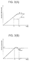
- FIG. 3 is a general characteristic line diagrams for describing the relationship between vehicle body deceleration and brake pressure in the brake control shown in FIG. 2 , with FIG. 3(A) being a characteristic line diagram generally showing an example of a change in brake pressure and FIG. 3(B) being a characteristic line diagram generally showing an example of a change in vehicle body deceleration when the change in brake in pressure shown in FIG. 3(A) occurs;
- FIG. 4 is a sub-routine flowchart showing a second example of brake control processing that is executed by the electronic control unit that configures the brake control system shown in FIG. 1 ;
- FIG. 5 is a general characteristic line diagrams for describing the relationship between vehicle body deceleration and brake pressure in the brake control shown in FIG. 4 , with FIG. 5(A) being a characteristic line diagram generally showing an example of a change in brake pressure and FIG. 5(B) being a characteristic line diagram generally showing an example of a change in vehicle body deceleration when the change in brake pressure shown in FIG. 5(A) occurs; and
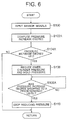
- FIG. 6 is a sub-routine flowchart showing a procedure of brake control processing when the magnitude of pressure increase of a front wheel cylinder is used as an index for judging whether or not there is the potential for rear wheel lifting.
- This brake control system S is broadly divided into a front brake master cylinder 1 that is disposed so as to be capable of converting the operational force of a brake handle 35 serving as a first brake operator into oil pressure, a rear brake master cylinder 2 that is disposed so as to be capable of converting the operational force of a brake pedal 36 serving as a second brake operator into oil pressure, a front wheel cylinder 3 that imparts brake force to a front wheel 37 in response to the oil pressure from the front brake master cylinder 1 , a rear wheel cylinder 4 that imparts brake force to a rear wheel 38 in response to the oil pressure from the rear brake master cylinder 2 , and an antilock brake control system 101 that is disposed between the front and rear brake master cylinders 1 and 2 and the front and rear wheel cylinders 3 and 4 .
- the front brake master cylinder 1 and the front wheel cylinder 3 are interconnected by a first main oil pressure tube 5 , and a front main oil pressure tube-use throttle 6 and a first electromagnetic valve 7 that is ordinarily in an opened state are disposed in order from the front brake master cylinder 1 side midway along the first main oil pressure tube 5 .
- a front main oil pressure tube-use check valve 8 is disposed so as to bypass the front main oil pressure tube-use throttle 6 and the first electromagnetic valve 7 and in a direction where it deters the reverse flow of brake oil (brake fluid) from the front wheel cylinder 3 to the front brake master cylinder 1 .
- the rear brake master cylinder 2 and the rear wheel cylinder 4 are interconnected by a second main oil pressure tube 9 , and a rear main oil pressure tube-use throttle 10 and a second electromagnetic valve 11 that is ordinarily in an opened state are disposed in order from the rear brake master cylinder 2 side midway along the second main oil pressure tube 9 .
- a rear main oil pressure tube-use check valve 12 is disposed so as to bypass the rear main oil pressure tube-use throttle 10 and the second electromagnetic valve 11 and in a direction where it deters the reverse flow of brake oil from the rear wheel cylinder 4 to the rear brake master cylinder 2 .
- a front reservoir connection-use oil pressure tube 13 is connected to an appropriate position of the first main oil pressure tube 5 between the first electromagnetic valve 7 and the front wheel cylinder 3 , a front reservoir-use throttle 14 and a front reservoir inflow control-use electromagnetic valve 15 are disposed in order from the front wheel cylinder 3 side midway along the front reservoir connection-use oil pressure tube 13 , and a front reservoir 16 is connected via these.
- the front reservoir inflow control-use electromagnetic valve 15 is ordinarily in a closed state.
- a front return-use oil pressure tube 17 that is communicated with the front brake master cylinder 1 is connected to the front reservoir connection-use oil pressure tube 13 at an appropriate position between the front reservoir inflow control-use electromagnetic valve 15 and the front reservoir 16 , and a front return path-use throttle 18 , a first front return path-use check valve 19 and a second front return path-use check valve 20 are disposed in order from the front brake master cylinder 1 side midway along the front return-use oil pressure tube 17 .
- a rear reservoir connection-use oil pressure tube 21 is connected to an appropriate position of the second main oil pressure tube 9 between the second electromagnetic valve 11 and the rear wheel cylinder 4 , a rear reservoir-use throttle 22 and a rear reservoir inflow control-use electromagnetic valve 23 are disposed in order from the rear wheel cylinder 4 side midway along the rear reservoir connection-use oil pressure tube 21 , and a rear reservoir 24 is connected via these.
- the rear reservoir inflow control-use electromagnetic valve 23 is ordinarily in a closed state.
- a front return-use oil pressure tube 25 that is communicated with the rear brake master cylinder 2 is connected to the rear reservoir connection-use oil pressure tube 21 at an appropriate position between the rear reservoir inflow control-use electromagnetic valve 23 and the rear reservoir 24 , and a rear return path-use throttle 26 , a first rear return path-use check valve 27 and a second rear return path-use check valve 28 are disposed in order from the rear brake master cylinder 2 side midway along the rear return-use oil pressure tube 25 .
- an oil pressure pump device 31 that is shared between the front brake and the rear brake is disposed in the antilock brake control system 101 . That is, the oil pressure pump device 31 is generally configured by a motor 32 and two plungers 33 a and 33 b that are reciprocally moved by an unillustrated fixed cam that is fixedly attached to an output shaft (not shown) of the motor 32 .
- the one plunger 33 a is connected between the first front return path-use check valve 19 and the second front return path-use check valve 20
- the other plunger 33 b is connected between the first rear return path-use check valve 27 and the second rear return path-use check valve 28
- the brake oil of the front reservoir 16 is sucked up and refluxed to the front brake master cylinder 1
- the brake oil of the rear reservoir 24 is sucked up and refluxed to the rear brake master cylinder 2 by the reciprocating motion of the plungers 33 a and 33 b.
- Control of the operation of each of the first and second electromagnetic valves 7 and 11 , the front reservoir inflow control-use electromagnetic valve 15 , the rear reservoir inflow control-use electromagnetic valve 23 and the motor 32 is performed by an electronic control unit (notated as “ECU” in FIG. 1 ) 51 .
- the electronic control unit 51 is configured to be disposed with a microcomputer (not shown) that has a publicly known/commonly known configuration and memory elements (not shown) such as a RAM and a ROM.
- the electronic control unit 51 executes various control programs for controlling the traveling of the vehicle that are stored in the unillustrated memory elements and performs various operation controls necessary for the driving and traveling of the vehicle. Examples of such operational controls of the vehicle include engine control, ABS control (Antilock Brake System), and processing to monitor the wheel velocities for determining whether or not there is an abnormality in wheel velocity sensors. Moreover, in the embodiment of the present invention, later-described brake control processing is executed.
- detection signals of wheel velocity sensors 45 and 46 that are correspondingly disposed in order to detect in the wheel velocities of the front wheel 37 and the rear wheel 38 , a detection signal of a first pressure sensor 47 that detects the generated pressure of the front brake master cylinder 1 , and a detection signal of a second pressure sensor 48 that detects the generated pressure of the front wheel cylinder 3 are inputted to the electronic control unit 51 .
- detection signals of a brake lever actuation switch (not shown) that detects actuation of the brake handle 35 and a brake pedal actuation switch (not shown) that detects actuation of the brake pedal 36 are also inputted to the electronic control unit 51 .
- a motor drive circuit 41 that generates and outputs a drive signal with respect to the motor 32 in response to a control signal from the electronic control unit 51 is disposed.
- an electromagnetic valve drive circuit 42 that controls the driving of the first and second electromagnetic valves 7 and 11 , the front reservoir inflow control-use electromagnetic valve 15 and the rear reservoir inflow control-use electromagnetic valve 23 in response to control signals from the electronic control unit 51 is disposed. It will be noted that, in FIG. 1 , the connections between the electromagnetic valve drive circuit 42 and the respective electromagnetic valves are omitted in order to simplify the drawing and make the drawing easier to understand.
- a predetermined detection signal corresponding to the fact that that operation has been detected by the actuation switch (not shown) that detects operation of the brake handle 35 is inputted to the electronic control unit 51 .
- brake fluid of an oil pressure corresponding to operation of the brake handle 35 is supplied from the brake master cylinder 1 to the wheel cylinder 3 , brake force is generated, and the brake force acts on the front wheel 37 .
- the electronic control unit 51 when it is judged that antilock brake control is necessary, the first electromagnetic valve 7 is excited, the first main oil pressure tube 5 is placed in a non-communicated state, and the oil pressure of the front wheel cylinder 3 is held at a constant. Then, in the electronic control unit 51 , when it is judged that the brake should be eased, the front reservoir inflow control-use electromagnetic valve 15 is excited. As a result, the brake fluid of the front wheel cylinder 3 is discharged to the front reservoir 16 via the front reservoir inflow control-use electromagnetic valve 15 , and the brake is eased.
- the motor 32 is driven by the electronic control unit 51 via the motor drive circuit 41 , and the brake fluid stored in the front reservoir 16 is sucked up by the motion of the plunger 33 a and refluxed to the front brake master cylinder 1 .
- brake force with respect to the wheel 38 is obtained in basically the same manner as in the case of the brake handle 35 aforementioned, and alleviation of the brake force is performed, so description here will be omitted.
- step S 100 When processing is started, first, at least the detection signals (sensor signals) of the wheel velocity sensors 45 and 46 are inputted to the electronic control unit 51 and temporarily saved in an unillustrated predetermined memory region (refer to step S 100 of FIG. 2 ). It will be noted that, in step S 100 , other sensor signals, that is, the detection signals of the pressure sensors 47 and 48 and the like, may also be inputted, and those input signals can be delivered when they are needed by other control processing outside of brake control processing.
- vehicle body deceleration (deceleration of vehicle body velocity) is performed on the basis of the detection signals of the wheel velocity sensors 45 and 46 that have been inputted (refer to step S 102 of FIG. 2 ).
- This vehicle body deceleration is calculated as an index for predicting the potential for lifting of the rear wheel resulting from sudden braking of the front wheel 37 , and this vehicle body deceleration is determined as follows. That is, first, pseudo vehicle body velocities are calculated by a predetermined arithmetic expression on the basis of the wheel velocities that have been detected by the wheel velocity sensors 45 and 46 .
- vehicle body deceleration is determined as being equal to (V 1 ⁇ V 2 )/ ⁇ t assuming that V 1 represents a pseudo vehicle body velocity at a given time t 1 and that V 2 represents a pseudo vehicle body velocity at a time t 2 after the elapse of a minute amount of time ⁇ t from time t 1 . It will be noted that, in the following description, “deceleration” means vehicle body deceleration.
- step S 104 it is determined whether or not the vehicle body deceleration that has been calculated as mentioned above exceeds a predetermined value K 1 (refer to step S 104 of FIG. 2 ), and when it is determined that the vehicle body deceleration does not exceed the predetermined value K 1 (in the case of NO), then the series of processing is ended and the sub-routine returns to an unillustrated main routine.
- step S 104 when it is determined that the vehicle body deceleration exceeds the predetermined value K 1 (in the case of YES), then it is determined that there is a large potential for rear wheel lifting, the sub-routine moves to the processing of the next step S 106 , and forced pressure reduction and holding of the pressure of the front wheel cylinder 3 are performed.
- predetermined signals for placing the first electromagnetic valve 7 in a closed state and for placing the front reservoir inflow control-use electromagnetic valve 15 in an opened state are outputted from the electronic control unit 51 to the electromagnetic valve drive circuit 42 , and the first electromagnetic valve 7 is placed in a closed state and the front reservoir inflow control-use electromagnetic valve 15 is placed in an opened state.
- communication between the front brake master cylinder 1 and the front wheel cylinder 3 is cut off, the brake fluid of the front wheel cylinder 3 is discharged to the front reservoir 16 , and pressure reduction of the front wheel cylinder 3 is performed. It is suitable for this pressure reduction of the front wheel cylinder 3 to be pressure reduction of a predetermined amount on the basis of the detection result of the second pressure sensor 48 , for example.
- FIG. 3(A) and FIG. 3(B) there are shown characteristic line diagrams generally showing a change in brake pressure and a change in vehicle body deceleration in the aforementioned brake control, and the same drawings will be described below.
- the pressure of the front brake master cylinder 1 and the front wheel cylinder 3 are substantially the same until time t 1 when pressure reduction of the front wheel cylinder 3 is performed, and that change in pressure is appropriately represented by a solid line, and the change in the pressure of the front wheel cylinder 3 from time t 1 on is represented by a two-dotted chain line.
- FIG. 3(A) there is shown by a solid line an example of a state where a sudden brake operation of the brake handle 35 is performed and brake pressure, that is, the pressures of the front brake master cylinder 1 and the front wheel cylinder 3 , increases substantially linearly as time elapses until time t 1 , and just the front brake master cylinder 1 still increases pressure from time t 1 on until it finally reaches a maximum pressure.
- FIG. 3(B) is an example of a change in vehicle body deceleration, and in this example, there is shown a state where vehicle body deceleration also increases together with the increase in brake pressure shown in FIG. 3(A) , exceeds the predetermined value K 1 at time t 1 , thereafter increases somewhat by the pressure reduction of the front wheel cylinder 3 that has been mentioned before, changes to a decrease, and then falls below the predetermined value K 1 .
- step S 106 the processing of step S 106 is executed as mentioned above, and thereafter it is determined whether or not vehicle body deceleration has dropped to a predetermined level (refer to step S 108 of FIG. 2 ).
- the predetermined level for judging a drop in vehicle body deceleration not just the previous predetermined value K 1 at the time of the rise in the amount of change, but a level (K 1 ⁇ ) equal to a predetermined amount a subtracted from the predetermined value K 1 is used as a judgment criterion, and a so-called hysteresis is disposed between the judgment level at the time of a rise in vehicle body deceleration and the judgment level at the time of a decrease.
- step S 108 when it is determined that vehicle body deceleration has fallen below the predetermined level (K 1 ⁇ ) (refer to the point in time of time t 2 of FIG. 3 (B)), the sub-routine proceeds to the processing of step S 110 , and forced pressure reduction of the front wheel cylinder 3 is stopped. That is, the first electromagnetic valve 7 is placed in an opened state by the electronic control unit 51 via the electromagnetic valve drive circuit 42 , and the front brake master cylinder 1 and the front wheel cylinder 3 return to a communicated state. For that reason, the pressure of the front brake master cylinder 1 is transmitted to the front wheel cylinder 3 , so the brake pressure resulting from the front wheel cylinder 3 rises (refer to time t 2 on of FIG. 3(A) ).
- step S 110 the sub-routine returns to the unillustrated main routine after the processing of step S 110 . Then, normal brake control is performed.
- FIG. 5(A) and FIG. 5(B) correspond to FIG. 3(A) and FIG. 3(B) , respectively, and as will be described below, just the way of a change in brake pressure resulting from a difference in pressure control of the front wheel cylinder 3 is different, and the remaining portions are basically the same as those shown in FIG. 3(A) and FIG. 3(B) .
- step S 104 when it is determined that vehicle body deceleration exceeds the predetermined value K 1 (in the case of YES), then the sub-routine proceeds to the processing of the next step S 106 A, and holding of the pressure of the front wheel cylinder 3 is performed. That is, a predetermined signal for placing the first electromagnetic valve 7 in a closed state is outputted from the electronic control unit 51 to the electromagnetic valve drive circuit 42 , the first electromagnetic valve 7 is placed in a closed state, and communication between the front brake master cylinder 1 and the front wheel cylinder 3 is cut off. For that reason, the pressure of the front wheel cylinder 3 is held at the pressure at that point in time (refer to the point in time of time t 1 of FIG. 5(A) and FIG. 5(B) ).
- step S 106 A it is determined whether or not vehicle body deceleration has fallen below the predetermined level (K 1 ⁇ ) (refer to step S 108 of FIG. 4 ), and when it is determined that vehicle body deceleration has fallen below the predetermined level (K 1 ⁇ ) (refer to the point in time of time t 2 of FIG. 5 (B)), then the sub-routine proceeds to the processing of step S 110 A, and holding of the pressure of the front wheel cylinder 3 is released. That is, the first electromagnetic valve 7 is placed in an opened state by the electronic control unit 51 via the electromagnetic valve drive circuit 42 , and the front brake master cylinder 1 and the front wheel cylinder 3 return to a communicated state. For that reason, the pressure of the front brake master cylinder 1 is transmitted to the front wheel cylinder 3 , and the brake pressure resulting from the front wheel cylinder 3 rises (refer to time t 2 on of FIG. 5(A) ).
- step S 110 A the sub-routine returns to the unillustrated main routine and normal brake control is performed.
- the brake control system was configured to determine whether or not there is the potential for rear wheel lifting by the magnitude of vehicle body deceleration, but the brake control system may also use the magnitude of the pressure increase degree of the front wheel cylinder 3 , or in other words, the amount of change in brake force, as a judgment index instead of vehicle body deceleration.
- FIG. 6 there is shown a sub-routine flowchart showing a procedure of brake control processing when the magnitude of the pressure increase degree of the front wheel cylinder 3 is used as an index for judging whether or not there is the potential for rear wheel lifting, and this control processing will be described below with reference to the drawing.
- step numbers will be given to steps having the same processing content as those in the sub-routine flowchart shown in FIG. 2 , detailed description of those steps having the same processing content will be omitted, and the points that are different will be mainly described below.
- step S 100 it is necessary for at least the detection signal of the second pressure sensor 48 to be inputted.
- step S 102 A the pressure increase degree of the front wheel cylinder 3 is computed and calculated on the basis of the detection signal of the second pressure sensor 48 .
- the pressure increase degree is determined as ⁇ p(t 0 + ⁇ t) ⁇ p(t 0 ) ⁇ / ⁇ t assuming that p(t 0 ) represents the pressure of the front wheel cylinder 3 at a given time t 0 and that p(t 0 + ⁇ t) represents the pressure of the front wheel cylinder 3 at a point in time after the elapse of a minute amount of time ⁇ t from there.
- step S 104 A when it is determined that the pressure increase degree exceeds the predetermined value P 1 (in the case of NO), then the series of processing is ended and the sub-routine returns to the unillustrated main routine.
- step S 104 A when it is determined that the pressure increase degree exceeds the predetermined value P 1 (in the case of YES), then it is determined that there is a large potential for rear wheel lifting, the sub-routine proceeds to the next step S 106 , and forced pressure reduction and holding of the pressure of the front wheel cylinder 3 are performed.
- step S 108 A of FIG. 6 it is determined whether or not the pressure increase degree has dropped to a predetermined level. It will be noted that, similar to what has been previously described in the processing of step S 108 of FIG. 2 , it is suitable for the determination level of the drop of the pressure increase degree to include a so-called hysteresis characteristic as a pressure increase degree (P 1 ⁇ ) that is lower by a predetermined value ⁇ with respect to the aforementioned predetermined value P 1 .
- P 1 ⁇ hysteresis characteristic
- pressure reduction stop processing is performed (refer to step S 110 of FIG. 6 ).
- the brake control system may also be configured to hold the pressure at the pressure of the front wheel cylinder 3 at that time is the same as the example described in FIG. 4 , so detailed description using a drawing corresponding to FIG. 4 will be omitted here.
- the present invention can be applied to a two-wheeled motor vehicle of which the demand for safety is high because of quick and accurate control of lifting of a rear wheel resulting from predicting lifting of the rear wheel by the value of a predetermined parameter and performing control of brake force in response to that prediction result.
- the invention is configured to predict the potential for lifting of the rear wheel before lifting of the rear wheel actually occurs and to control brake force in response thereto, whereby the invention provides the effects that, contrary to what has conventionally been the case where control of brake force has been performed in response to actual lifting of the rear wheel, brake control that can control the rear wheel lifting quickly and accurately and shorten brake distance can be realized, and therefore a vehicle whose safety in and reliability are higher in comparison to what has conventionally been the case can be provided.
Landscapes
- Engineering & Computer Science (AREA)
- Transportation (AREA)
- Mechanical Engineering (AREA)
- Hydraulic Control Valves For Brake Systems (AREA)
- Regulating Braking Force (AREA)
Applications Claiming Priority (1)
| Application Number | Priority Date | Filing Date | Title |
|---|---|---|---|
| PCT/JP2006/301037 WO2007086103A1 (ja) | 2006-01-24 | 2006-01-24 | ブレーキ制御方法及びその装置 |
Publications (2)
| Publication Number | Publication Date |
|---|---|
| US20100225158A1 US20100225158A1 (en) | 2010-09-09 |
| US8070237B2 true US8070237B2 (en) | 2011-12-06 |
Family
ID=38308913
Family Applications (1)
| Application Number | Title | Priority Date | Filing Date |
|---|---|---|---|
| US12/161,367 Active 2027-02-09 US8070237B2 (en) | 2006-01-24 | 2006-01-24 | Brake control method and system |
Country Status (6)
| Country | Link |
|---|---|
| US (1) | US8070237B2 (de) |
| EP (1) | EP1980461B1 (de) |
| JP (1) | JP5014159B2 (de) |
| DE (1) | DE602006018366D1 (de) |
| ES (1) | ES2355929T3 (de) |
| WO (1) | WO2007086103A1 (de) |
Cited By (3)
| Publication number | Priority date | Publication date | Assignee | Title |
|---|---|---|---|---|
| US20100138122A1 (en) * | 2007-02-23 | 2010-06-03 | Helge Westerfeld | Brake Control Method And Brake Control Device For Two-Wheeled Motor Vehicle |
| US20130018561A1 (en) * | 2010-03-31 | 2013-01-17 | Bosch Corporation | Brake hydraulic control method and system |
| US10640096B2 (en) * | 2017-03-14 | 2020-05-05 | Nissin Kogyo Co., Ltd. | Brake fluid pressure control device for vehicles with bar handle |
Families Citing this family (3)
| Publication number | Priority date | Publication date | Assignee | Title |
|---|---|---|---|---|
| US20090048753A1 (en) * | 2006-01-31 | 2009-02-19 | Takahiro Ogawa | Two-wheeled motor vehicle brake control method and system |
| JP2019209710A (ja) | 2018-05-31 | 2019-12-12 | ロベルト・ボッシュ・ゲゼルシャフト・ミト・ベシュレンクテル・ハフツングRobert Bosch Gmbh | ブレーキ液圧制御装置、鞍乗型車両、及び、ブレーキ液圧制御方法 |
| JP2020175690A (ja) * | 2019-04-15 | 2020-10-29 | ロベルト・ボッシュ・ゲゼルシャフト・ミト・ベシュレンクテル・ハフツングRobert Bosch Gmbh | 制御システム及び制御方法 |
Citations (20)
| Publication number | Priority date | Publication date | Assignee | Title |
|---|---|---|---|---|
| US3871713A (en) | 1971-05-17 | 1975-03-18 | Paul M Lister | Braking system for vehicles having speed controlled proportional braking for front and rear wheels |
| US5116108A (en) | 1988-01-19 | 1992-05-26 | Robert Bosch Gmbh | Drive slip control system |
| JPH0597085A (ja) | 1991-10-08 | 1993-04-20 | Honda Motor Co Ltd | 車体状態検出方法および装置 |
| US5261730A (en) | 1991-01-29 | 1993-11-16 | Mercedes-Benz Ag | Brake pressure control device |
| US5324102A (en) | 1991-10-18 | 1994-06-28 | Fag Kugelfischer Georg Schafer Kgaa | Method and apparatus for regulating the braking force of motorcycles |
| US5386366A (en) | 1992-01-10 | 1995-01-31 | S:Fag Kugelfischer Georg Schafer Kgaa | Method of regulating the braking force of motorcycles |
| JPH07242166A (ja) | 1994-03-07 | 1995-09-19 | Toyota Motor Corp | 制動力制御装置 |
| JP2727907B2 (ja) | 1993-03-01 | 1998-03-18 | 株式会社デンソー | ブレーキ制御装置 |
| JP2002029403A (ja) | 2000-05-11 | 2002-01-29 | Bosch Braking Systems Co Ltd | 二輪車の後輪浮き上がり検出方法およびブレーキ制御方法 |
| JP2002029397A (ja) | 2000-07-12 | 2002-01-29 | Toyota Motor Corp | 車輌用制動力制御装置 |
| JP3416819B2 (ja) | 1991-10-18 | 2003-06-16 | フアーク・クーゲルフイツシエル・ゲオルク・シエーフエル・コマンデイートゲゼルシヤフト・アウフ・アクチエン | 自動二輪車の制動力調整する方法及び装置 |
| US6672437B2 (en) | 2000-06-29 | 2004-01-06 | Sa Beringer | Motor vehicle braking device |
| US20070185623A1 (en) * | 2006-02-03 | 2007-08-09 | Shih-Ken Chen | Vehicle wheel lift detection |
| US7302331B2 (en) * | 2002-08-01 | 2007-11-27 | Ford Global Technologies, Inc. | Wheel lift identification for an automotive vehicle |
| US20080281487A1 (en) * | 2004-03-23 | 2008-11-13 | Kelsey-Hayes Company | Method and Apparatus for Vehicle Rollover Mitigation |
| US20090048753A1 (en) * | 2006-01-31 | 2009-02-19 | Takahiro Ogawa | Two-wheeled motor vehicle brake control method and system |
| US20090055066A1 (en) * | 2006-02-08 | 2009-02-26 | Shunsaku Ono | Two-wheeled motor vehicle brake control method and brake control system |
| US7653471B2 (en) * | 2003-02-26 | 2010-01-26 | Ford Global Technologies, Llc | Active driven wheel lift identification for an automotive vehicle |
| US20100138122A1 (en) * | 2007-02-23 | 2010-06-03 | Helge Westerfeld | Brake Control Method And Brake Control Device For Two-Wheeled Motor Vehicle |
| US20100145574A1 (en) * | 2003-02-26 | 2010-06-10 | Ford Global Technologies, Llc. | Active Driven Wheel Lift Identification for an Automotive Vehicle |
-
2006
- 2006-01-24 DE DE602006018366T patent/DE602006018366D1/de not_active Expired - Lifetime
- 2006-01-24 JP JP2007555793A patent/JP5014159B2/ja not_active Expired - Lifetime
- 2006-01-24 US US12/161,367 patent/US8070237B2/en active Active
- 2006-01-24 ES ES06712253T patent/ES2355929T3/es not_active Expired - Lifetime
- 2006-01-24 WO PCT/JP2006/301037 patent/WO2007086103A1/ja not_active Ceased
- 2006-01-24 EP EP06712253A patent/EP1980461B1/de not_active Expired - Lifetime
Patent Citations (20)
| Publication number | Priority date | Publication date | Assignee | Title |
|---|---|---|---|---|
| US3871713A (en) | 1971-05-17 | 1975-03-18 | Paul M Lister | Braking system for vehicles having speed controlled proportional braking for front and rear wheels |
| US5116108A (en) | 1988-01-19 | 1992-05-26 | Robert Bosch Gmbh | Drive slip control system |
| US5261730A (en) | 1991-01-29 | 1993-11-16 | Mercedes-Benz Ag | Brake pressure control device |
| JPH0597085A (ja) | 1991-10-08 | 1993-04-20 | Honda Motor Co Ltd | 車体状態検出方法および装置 |
| JP3416819B2 (ja) | 1991-10-18 | 2003-06-16 | フアーク・クーゲルフイツシエル・ゲオルク・シエーフエル・コマンデイートゲゼルシヤフト・アウフ・アクチエン | 自動二輪車の制動力調整する方法及び装置 |
| US5324102A (en) | 1991-10-18 | 1994-06-28 | Fag Kugelfischer Georg Schafer Kgaa | Method and apparatus for regulating the braking force of motorcycles |
| US5386366A (en) | 1992-01-10 | 1995-01-31 | S:Fag Kugelfischer Georg Schafer Kgaa | Method of regulating the braking force of motorcycles |
| JP2727907B2 (ja) | 1993-03-01 | 1998-03-18 | 株式会社デンソー | ブレーキ制御装置 |
| JPH07242166A (ja) | 1994-03-07 | 1995-09-19 | Toyota Motor Corp | 制動力制御装置 |
| JP2002029403A (ja) | 2000-05-11 | 2002-01-29 | Bosch Braking Systems Co Ltd | 二輪車の後輪浮き上がり検出方法およびブレーキ制御方法 |
| US6672437B2 (en) | 2000-06-29 | 2004-01-06 | Sa Beringer | Motor vehicle braking device |
| JP2002029397A (ja) | 2000-07-12 | 2002-01-29 | Toyota Motor Corp | 車輌用制動力制御装置 |
| US7302331B2 (en) * | 2002-08-01 | 2007-11-27 | Ford Global Technologies, Inc. | Wheel lift identification for an automotive vehicle |
| US7653471B2 (en) * | 2003-02-26 | 2010-01-26 | Ford Global Technologies, Llc | Active driven wheel lift identification for an automotive vehicle |
| US20100145574A1 (en) * | 2003-02-26 | 2010-06-10 | Ford Global Technologies, Llc. | Active Driven Wheel Lift Identification for an Automotive Vehicle |
| US20080281487A1 (en) * | 2004-03-23 | 2008-11-13 | Kelsey-Hayes Company | Method and Apparatus for Vehicle Rollover Mitigation |
| US20090048753A1 (en) * | 2006-01-31 | 2009-02-19 | Takahiro Ogawa | Two-wheeled motor vehicle brake control method and system |
| US20070185623A1 (en) * | 2006-02-03 | 2007-08-09 | Shih-Ken Chen | Vehicle wheel lift detection |
| US20090055066A1 (en) * | 2006-02-08 | 2009-02-26 | Shunsaku Ono | Two-wheeled motor vehicle brake control method and brake control system |
| US20100138122A1 (en) * | 2007-02-23 | 2010-06-03 | Helge Westerfeld | Brake Control Method And Brake Control Device For Two-Wheeled Motor Vehicle |
Cited By (5)
| Publication number | Priority date | Publication date | Assignee | Title |
|---|---|---|---|---|
| US20100138122A1 (en) * | 2007-02-23 | 2010-06-03 | Helge Westerfeld | Brake Control Method And Brake Control Device For Two-Wheeled Motor Vehicle |
| US8290678B2 (en) * | 2007-02-23 | 2012-10-16 | Bosch Corporation | Brake control method and brake control device for two-wheeled motor vehicle |
| US20130018561A1 (en) * | 2010-03-31 | 2013-01-17 | Bosch Corporation | Brake hydraulic control method and system |
| US8831850B2 (en) * | 2010-03-31 | 2014-09-09 | Bosch Corporation | Brake hydraulic control method and system |
| US10640096B2 (en) * | 2017-03-14 | 2020-05-05 | Nissin Kogyo Co., Ltd. | Brake fluid pressure control device for vehicles with bar handle |
Also Published As
| Publication number | Publication date |
|---|---|
| JPWO2007086103A1 (ja) | 2009-06-18 |
| EP1980461A4 (de) | 2010-02-17 |
| WO2007086103A1 (ja) | 2007-08-02 |
| DE602006018366D1 (de) | 2010-12-30 |
| EP1980461A1 (de) | 2008-10-15 |
| EP1980461B1 (de) | 2010-11-17 |
| US20100225158A1 (en) | 2010-09-09 |
| ES2355929T3 (es) | 2011-04-01 |
| JP5014159B2 (ja) | 2012-08-29 |
Similar Documents
| Publication | Publication Date | Title |
|---|---|---|
| EP1842755B1 (de) | Bremskontrollvorrichtung für ein Motorrad | |
| US20090048753A1 (en) | Two-wheeled motor vehicle brake control method and system | |
| US9643612B2 (en) | Vehicle control unit | |
| US8290678B2 (en) | Brake control method and brake control device for two-wheeled motor vehicle | |
| US7444221B2 (en) | Vehicle backward movement detection apparatus and vehicle braking force control apparatus | |
| US9643578B2 (en) | Vehicle control unit | |
| US8185286B2 (en) | Two-wheeled motor vehicle brake control method and brake control system | |
| US8150590B2 (en) | Two-wheeled motor vehicle brake control method and system | |
| US8070237B2 (en) | Brake control method and system | |
| CN104228799A (zh) | 车辆用制动液压控制装置 | |
| US8186769B2 (en) | Two-wheeled motor vehicle brake control method and system |
Legal Events
| Date | Code | Title | Description |
|---|---|---|---|
| AS | Assignment |
Owner name: BOSCH CORPORATION (50%), JAPAN Free format text: ASSIGNMENT OF ASSIGNORS INTEREST;ASSIGNORS:OGAWA, TAKAHIRO;WESTERFELD, HELGE;HAMM, MARKUS;SIGNING DATES FROM 20080618 TO 20080623;REEL/FRAME:024498/0049 Owner name: BAYERISCHE MOTOREN WERKE AKTIENGESELLSCHAFT (50%), Free format text: ASSIGNMENT OF ASSIGNORS INTEREST;ASSIGNORS:OGAWA, TAKAHIRO;WESTERFELD, HELGE;HAMM, MARKUS;SIGNING DATES FROM 20080618 TO 20080623;REEL/FRAME:024498/0049 |
|
| STCF | Information on status: patent grant |
Free format text: PATENTED CASE |
|
| CC | Certificate of correction | ||
| FPAY | Fee payment |
Year of fee payment: 4 |
|
| MAFP | Maintenance fee payment |
Free format text: PAYMENT OF MAINTENANCE FEE, 8TH YEAR, LARGE ENTITY (ORIGINAL EVENT CODE: M1552); ENTITY STATUS OF PATENT OWNER: LARGE ENTITY Year of fee payment: 8 |
|
| MAFP | Maintenance fee payment |
Free format text: PAYMENT OF MAINTENANCE FEE, 12TH YEAR, LARGE ENTITY (ORIGINAL EVENT CODE: M1553); ENTITY STATUS OF PATENT OWNER: LARGE ENTITY Year of fee payment: 12 |