US8065110B2 - System and method for evaluation of fluid flow in a piping system - Google Patents
System and method for evaluation of fluid flow in a piping system Download PDFInfo
- Publication number
- US8065110B2 US8065110B2 US10/942,817 US94281704A US8065110B2 US 8065110 B2 US8065110 B2 US 8065110B2 US 94281704 A US94281704 A US 94281704A US 8065110 B2 US8065110 B2 US 8065110B2
- Authority
- US
- United States
- Prior art keywords
- liquid
- sprinklers
- time
- inch
- pipe
- Prior art date
- Legal status (The legal status is an assumption and is not a legal conclusion. Google has not performed a legal analysis and makes no representation as to the accuracy of the status listed.)
- Expired - Lifetime, expires
Links
Images


Classifications
-
- A—HUMAN NECESSITIES
- A62—LIFE-SAVING; FIRE-FIGHTING
- A62C—FIRE-FIGHTING
- A62C35/00—Permanently-installed equipment
- A62C35/58—Pipe-line systems
- A62C35/62—Pipe-line systems dry, i.e. empty of extinguishing material when not in use
-
- G—PHYSICS
- G05—CONTROLLING; REGULATING
- G05B—CONTROL OR REGULATING SYSTEMS IN GENERAL; FUNCTIONAL ELEMENTS OF SUCH SYSTEMS; MONITORING OR TESTING ARRANGEMENTS FOR SUCH SYSTEMS OR ELEMENTS
- G05B17/00—Systems involving the use of models or simulators of said systems
- G05B17/02—Systems involving the use of models or simulators of said systems electric
-
- G—PHYSICS
- G06—COMPUTING OR CALCULATING; COUNTING
- G06F—ELECTRIC DIGITAL DATA PROCESSING
- G06F30/00—Computer-aided design [CAD]
-
- G—PHYSICS
- G06—COMPUTING OR CALCULATING; COUNTING
- G06F—ELECTRIC DIGITAL DATA PROCESSING
- G06F30/00—Computer-aided design [CAD]
- G06F30/10—Geometric CAD
- G06F30/13—Architectural design, e.g. computer-aided architectural design [CAAD] related to design of buildings, bridges, landscapes, production plants or roads
-
- G—PHYSICS
- G06—COMPUTING OR CALCULATING; COUNTING
- G06F—ELECTRIC DIGITAL DATA PROCESSING
- G06F30/00—Computer-aided design [CAD]
- G06F30/20—Design optimisation, verification or simulation
-
- G—PHYSICS
- G06—COMPUTING OR CALCULATING; COUNTING
- G06F—ELECTRIC DIGITAL DATA PROCESSING
- G06F30/00—Computer-aided design [CAD]
- G06F30/20—Design optimisation, verification or simulation
- G06F30/28—Design optimisation, verification or simulation using fluid dynamics, e.g. using Navier-Stokes equations or computational fluid dynamics [CFD]
-
- G—PHYSICS
- G06—COMPUTING OR CALCULATING; COUNTING
- G06G—ANALOGUE COMPUTERS
- G06G7/00—Devices in which the computing operation is performed by varying electric or magnetic quantities
- G06G7/48—Analogue computers for specific processes, systems or devices, e.g. simulators
- G06G7/50—Analogue computers for specific processes, systems or devices, e.g. simulators for distribution networks, e.g. for fluids
-
- G—PHYSICS
- G06—COMPUTING OR CALCULATING; COUNTING
- G06F—ELECTRIC DIGITAL DATA PROCESSING
- G06F2111/00—Details relating to CAD techniques
- G06F2111/10—Numerical modelling
-
- G—PHYSICS
- G06—COMPUTING OR CALCULATING; COUNTING
- G06F—ELECTRIC DIGITAL DATA PROCESSING
- G06F2113/00—Details relating to the application field
- G06F2113/14—Pipes
Definitions
- the modeling of real-world systems through mathematics has been utilized to determine how systems response to real-world inputs. Due to the nature of such modeling, computers are often used to assist in such modeling.
- the modeling of liquid and gas flow in piping network presents a situation in which the more detailed the piping network, the more difficult it is to model such piping network, and in most cases, the model does not correlate accurately with real-world piping networks.
- One area of modeling in piping network is the determination of the location of the liquid front as the liquid moves through the piping that was previously occupied by another liquid or gas. Where the liquid is moving through a single uniform straight pipe, it is believed that an accurate model, i.e., an analytical model, of the characteristics of the liquid can be obtained. Where a movement of the liquid is initiated at some point in a large network of branching pipes so that the liquid flows through the network thereafter, it is believed that the current analytical models are inadequate for such type of complex networks.
- These complex piping networks are utilized in the fire protection industry, and, in particular for providing a sprinkler system.
- the pipe is filed with a gas and liquid enters the piping network once the gas is expelled from the piping network by actuation of a sprinkler.
- These pipe networks are known as “dry pipe” sprinkler systems. Dry pipe sprinkler systems are utilized in areas that are unheated and that are subjected to freezing temperatures.
- the sprinkler piping for a dry system is, preferably, filled with air under pressure. The air pressure in the system holds a dry pipe valve closed, and the valve opens with a loss of air pressure in the system.
- actuation of one or more sprinklers will allow air to escape the piping network and result in the tripping of the dry pipe valve and the filling of the piping network with water (to the sprinklers).
- a dry sprinkler system is slower to respond to fire conditions than a wet system because the air must first be exhausted from the system.
- NFPA 13 provides for certain dry pipe sprinkler systems to be installed without testing.
- NFPA 13 is the governing standard for the sprinkler system, if such individuals elect to install a system and it fails the required actual testing, the individuals would have to modify or re-design and re-install the system to conform within the requirements of NFPA 13.
- the performance of a test introduces water into the piping system. Following the test, the water is drained from the system prior to re-introducing air pressure. Often, water is trapped within the pipes and causes freezing problems after the system is put into service. Another effect of introducing water into the piping network, draining it, and filling the system with air is that any residual moisture can settle and cause premature corrosion within the steel pipe. Hence, it is desirable to avoid actual testings.
- FMRC Factory Mutual Research Corporation
- FMRC provides for the known fixed topology model that fixes a test sprinkler head on the same branch regardless of where in the actual design the test sprinkler would be the one hydraulically farthest from the dry pipe valve would be located; and the riser is fixed to the middle of a cross main piping regardless of where such riser is to be placed in an actual design.
- the known model is believed to be unreliable because of the forced translation from the arbitrary design into the fixed topology of known model.
- the known model summarizes (i.e., “lumps”) all branch lines before and after a main feed line (i.e., “Feed Main”) as respective volumes instead of accounting for liquid flow, gas flow and liquid-gas flow behavior in each pipe.
- the known model in utilizing a forced translation and lumped volumes, provided predictive values for liquid flow that are believed to be higher than a suitable threshold for individuals (e.g., engineer, architects, planners, contractors and jurisdictional authorities) to rely upon.
- individuals e.g., engineer, architects, planners, contractors and jurisdictional authorities
- the known model may provide a generalized technique to analyze dry pipe systems but does not account for flow through each pipe so that individuals can use the predictive results with a suitable degree of accuracy.
- the present invention provides for a method to model a complex system of pipes accurately.
- This model takes into account the physical processes in every part of a tree-type piping system and provides for an accurate modeling of a real world tree-type piping system.
- the preferred embodiments of this model have been verified by comparisons against known piping systems.
- the present invention provides a schema to determine liquid flow, gas flow and their interactions in piping systems that was heretofore believed to be unavailable.
- the preferred embodiments of the present invention have reliably predicted a transit time of liquid flow through referential tree-type piping systems by evaluating the flow of liquid, gas or mixture thereof through each pipe of the tree-type piping system.
- the preferred embodiments employ at least one computational engine that is capable of predicting time based response characteristics of known referential tree-type piping systems within a variance believed not to be achieved by other models.
- the preferred embodiments achieves a variance or error of 12%, 7%, 3%, 4%, 1% and even 0% depending on the referential system employed.
- the behavior and characteristics of the liquid and gas flow at every point in the piping system are accounted for in the piping system.
- the preferred embodiments are capable of predicting behavior and characteristics of various liquids and fluids such as, for example, propyl alcohol, ethylene glycol, or water at every point of the piping system.
- the preferred embodiments estimate a time duration for gas pressure in the piping network to drop below a threshold pressure when the gas is permitted to escape from the network through an open node by: (a) determining whether a ratio of atmospheric pressure to internal pressure in the network is less than a first ratio or at least equal to a second ratio; (b) calculating that the mass flow rate of the gas as being a function of a discharge area, pressure and temperature of the discharge area from the system is less than the first ratio and the mass flow rate of the gas as being a function of a discharge area, pressure, temperature of the discharge area and a ratio of ambient pressure to pressure at the discharge area when the ratio is at least equal to the second ratio; (c) relating the mass flow rate to a change in pressure of the gas, its velocity and temperature at the discharge area; and (d) solving for a change in gas pressure in the system over time as a function of mass flow rate, temperature, velocity, and pressure at the discharge area.
- the preferred embodiments also approximate a duration of time for any liquid front traveling from an initial location in the piping network to a discharge opening in the network (i.e., a transit time) by: (a) accounting for a velocity of the liquid as the liquid moves from the initial position to at least one of a segment of the network without a branch, a segment to a node with two branches, and a segment to a node with three branches in the network; (b) accounting for a representative velocity of bubbles as liquid and gas travels through the network; (c) determining the losses as the liquid moves through at least one of a segment of the network without a branch, a segment to a node with two branches, and a segment to a node with three branches in the network; and (d) determining whether gas flow in the system is one of an adiabatic or isothermal process. Furthermore, the preferred embodiments determine an approximation of a change in pressure of the liquid compared to time as the liquid front travels from the initial location to the discharge opening based on
- the present invention also provides for, in a preferred embodiment, a computer program for analyzing models of dry pipe systems.
- the computer program includes a user interface and a computational engine.
- the user interface allows a model of a dry pipe system to be defined and the computational engine determines a liquid flow time through the model of the dry pipe system.
- the computational engine that employs the methods of the preferred embodiments, and provides a verification of the liquid flow time in a model of a referential dry pipe system within 20% of an actual liquid flow time in the referential dry pipe system.
- the present invention further provides for, in another preferred embodiment, a method for use in a development of a tree-type piping system.
- the method can be achieved by generating at least a time-based characteristic of liquid flow through the tree-type piping system.
- the at least a time based characteristic has a value based on a calculation process that evaluates the physical processes of liquid and gas flow in each pipe of the tree-type piping system.
- the present invention additionally provides for, in yet another preferred embodiment, a process of installing a dry pipe sprinkler system.
- the process can be achieved by: determining a liquid delivery time of a liquid at a sprinkler head or a nozzle when the sprinkler or nozzle is actuated in a model of a dry pipe sprinkler system; and constructing a dry pipe fire sprinkler system based on the model of the dry pipe sprinkler without physical verification of the predicted transit time.
- the liquid delivery time is determined to be less than a desired value.
- the process provides for the ability to prototype, plan and evaluate a new dry pipe system.
- the process also provides for the ability to retrofit an existing dry pipe system to meet desired criteria to ensure an adequate response for the existing system.
- FIG. 1 depicts a graphical user interface displaying a 3-D wire frame model of a first referential dry pipe fire protection system of a preferred embodiment of a dry pipe computer modeling program embodied in the graphical user interface.
- FIG. 2 depicts results of the analysis of the model in graphical form by the graphical interface utilizing a preferred embodiment of the dry pipe computer-modeling program.
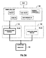
- FIG. 3A illustrates a flow chart of a preferred embodiment of the computer-modeling program.
- FIG. 3B illustrates in further detail a subsection of the flow chart of FIG. 3A .
- FIG. 3C illustrates in further detail of another subsection of the flow chart of FIG. 3A .
- FIG. 4A illustrate a second referential model that can be used to verify the results of the computer-modeling program.
- FIG. 4B illustrates a third referential model that can be used to verify the results of the computer-modeling program.
- FIG. 4C illustrates a fourth referential model that can be used to verify the results of the computer-modeling program.
- FIG. 1 depicts a graphical user interface that permits a system of tree-type fluid transporting network to be modeled in order to predict certain characteristics of the system, such as, for example, a valve actuation or trip time (i.e., the time it takes for a gas pressure in the system to drop below a threshold that allows a fluid to flow into the system), transient time (i.e., the time it takes for a fluid to reach one or more opening of the system) and steady state time (i.e., the time is takes for the fluid flowing through the network to the opening to reach a steady state flow condition).
- a valve actuation or trip time i.e., the time it takes for a gas pressure in the system to drop below a threshold that allows a fluid to flow into the system
- transient time i.e., the time it takes for a fluid to reach one or more opening of the system
- steady state time i.e., the time is takes for the fluid flowing through the network to the opening to reach a steady state flow condition
- the model of the piping system is composed of piping segments and piping connections.
- the piping segments are characterized by lines and the piping connections are characterized by nodes. Nodes can represent either a point of transition from one pipe size to another, elbows or bends, tees and laterals for dividing or mixing streams and valves, and exit opening.
- the fluid supply can be modeled as either a static fluid supply or variable fluid supply (i.e., pump driven fluid supply). Currently, the model accepts one fluid supply source and can accept fluid from more than one source.
- the fluid is a fire fighting fluid such as water or Inergen® and the gas is nitrogen or ambient air.
- the program can evaluate other fluids including any single-phase flow of liquid base on the fluid's corresponding density, specific gravity, or specific weight. That is, the program is capable of predicting the delivery of any single-phase fluid in a piping network where the fluid delivery is controlled from a location that is remote from the point of delivery. For example, if the piping network is unsupervised, and contains air at atmospheric pressure, this can be entered into the model using the specific gravity of air and a pressure of 14.7 psi, or one bar. Similarly, if a liquid is being delivered in that network, the flow of the liquid can be predicted in the program by entering the physical properties (specific gravity, or density, or specific weight) of the fluid being delivered.
- the computer program can model a piping system to predict the trip time, delivery time and steady state time of a flow of propyl alcohol in the system from a trip valve proximate a supply to an opening at the farthest location from the trip valve.
- the system in this model can be configured with a main line with 20 branch lines in a tree-type array and may be provided with a system volume of about 1111 gallons and initially filled with pressurized Nitrogen gas at 100 degrees Fahrenheit.
- the computer program can predict the trip time, delivery time and steady state time of a flow of ethylene glycol in the system from a trip valve proximate a supply to an opening at the farthest location from the trip valve.
- the system in this model can be configured with a main line with 20 branch lines in a tree-type array and may be provided with a system volume of about 1111 gallons and initially filled with pressurized Nitrogen gas at 100 degrees Fahrenheit.
- the computer program can predict the trip time, delivery time and steady state time of a flow of water. For example, at least eight actual referential dry pipe systems provided with an array of twelve branch lines, and two cross mains were modeled and the liquid delivery time for each was predicted by the computer program.
- the computer program is not limited to fire protection and can be used to calculate a fluid transit time for other applications involving fluid delivery through a piping network such as, for example, a piping network in a hospital from a centralized source to a given patient room or point of application; a piping network for oil, other petroleum or non-petroleum chemical liquid product (e.g., isopropyl alcohol, ethylene glycol) or water through a distribution network in a pipeline or city grid of water mains, or a piping network to deliver paint or other fluids to a remote location or to robotic painting machine in an industry such as automobile manufacturing.
- a piping network such as, for example, a piping network in a hospital from a centralized source to a given patient room or point of application
- a piping network for oil, other petroleum or non-petroleum chemical liquid product e.g., isopropyl alcohol, ethylene glycol
- water e.g., isopropyl alcohol, ethylene glycol
- the piping system can be modeled as a tree-type system (i.e., a single cross-main supplies fluid to branch pipes that are fitted with automatic sprinklers).
- Each pipe or node in the model is categorized as members of either a Feed Main, Cross Main, Riser Nipple, Branch Line and drop/sprig portion of the dry pipe system.
- the user can create a dry pipe tree system by specifying a total number of sprinkler based on the number of branch pipes multiplied with the number of sprinklers, the total coverage area based on the distance between branch pipes multiplied with the distance between sprinklers.
- the user provides information as to the number of sprinkler heads from the left side of the system the main will be located; location and length of the feed main; elevations of the sprinklers and pipes; and a fluid supply.
- the computer program in connection with a computer, generates a line-node-model of the dry pipe system on a graphical display screen.
- the line-node model can be displayed as a plan view, front view, side view, top view, or perspective view rotatable about a predefined origin.
- the line-node model provides information as to the number of pipes and “nodes” in the system. By viewing the line-node model plan, the user can modify the system as required for any desired configuration of the dry pipe system.
- the computer program is configured to allow the user to enter physical attributes of the respective sprinklers and pipes.
- the user can enter the K-factor, orifice diameter, minimum operating pressure and other data suitable to provide a representation of a sprinkler at a specified location in the system.
- the user can specify whether the pipe is a branch line, cross-main, drop, or feed-main; the starting and ending nodes that the pipe is connected to, pipe schedule, size, internal diameter, Hazen Williams C-Factor, absolute roughness, length, fittings, equivalent length, total length and other suitable attributes in modeling the dry pipe system.
- Each of the nodes generally require data input on its suitable physical attributes such as, for example, whether the node is a supply, heads, non-flowing node, X-Y orientation, elevation, closed or open configuration, K-factor, orifice diameter, operating time and other attributes suitable for the computer program to function for its intended purpose in modeling a hydraulic system, which preferably is a dry pipe system.
- suitable physical attributes such as, for example, whether the node is a supply, heads, non-flowing node, X-Y orientation, elevation, closed or open configuration, K-factor, orifice diameter, operating time and other attributes suitable for the computer program to function for its intended purpose in modeling a hydraulic system, which preferably is a dry pipe system.
- the computer program builds a model of the dry pipe system that is represented by mathematical equations.
- the model of the dry pipe system allows for the computer program to simulate various time based response characteristics of the dry pipe system such as, for example, trip time, transit time and operating pressure time, during an actuation of any sprinkler head in the piping network using one or more computational engine.
- the reconfigured program can be used to model dry pipe systems with loops in the pipes, pumps (e.g., fire pump), one-way valve (e.g., backflow preventer), valve opening accelerator, and sequential fluid deliveries (e.g., consecutive sprinklers actuation) in the system.
- a display window located at the far left upper corner of the display with heading h 1 illustrates pressure and flow as a function of time, respectively for the characteristic of the trip time for the modeled system.
- a display window on the right corner with heading h 2 illustrates the pressure and flow of the modeled system as a function of time, respectively, for the characteristic of transit time.
- a large window with heading h 3 illustrates the pressure and flow rate of the modeled system as a function of time, respectively, for the characteristic of operating pressure time.
- files regarding physical attributes of the system such as attributes of the pipes, number of nodes, supply, fluid, gases and program parameters, as discussed earlier for a model of a dry pipe system, are prepared in a suitable format for processing. Other processing such as, for example, conversion from English units to SI units is also performed here.
- the data can be used by computational engines to determine at least one desired physical response of the model such as, for example, a dry pipe valve trip time and fluid transit time.
- FLOWCALC is based on energy equations for liquid and temperature relaxation equations for a moving gas
- PIPEFLOW is based on momentum balance equations for a gas, liquid or gas-liquid mix control volume in each of the pipes of the system.
- FLOWCALC may be thought of as a modeling approach which solves the equations of motion in the vicinity of the flow front (i.e., the furthest downstream areas of fluid flow) whereas PIPEFLOW may be thought of as a modeling approach which solves the equations for motion for each pipe in the system during the entire transient flow period. That is, FLOWCALC creates and solves the system of equations describing pipes with liquid considering gas, either entrapped or being depleted through open sprinkler(s), to impose pressure upon the liquid front(s). It alters the system of equations depending on what system components are filled with liquid adding gas pressure components to liquid fronts, if any, in the pipe at consideration.
- PIPEFLOW creates and solves the system of equations describing the entire piping system for the entire calculation process/period. It alters system component parameters depending on actual media flowing in the component—either liquid or gas.
- the preferred embodiments of the computational engine can provide a correlation of less than 20% between a computer model and its corresponding physical piping network.
- Each computational engine can be used alone or in combination with the other computational engine. In the latter case, the two computational engines can provide a degree of redundancy and error cross-checking.
- FLOWCALC is presently the preferred method of solving the transient fluid flow problem because it can solve the problem more efficiently (essentially because there are fewer equations to solve), although both PIPEFLOW and FLOWCALC are found to provide comparable predictions to actual test results.
- the mathematical framework used to solve for the dry pipe valve trip time, transit and steady state flow times as embodied in the FLOWCALC computational engine for a user-defined piping system will now be described.
- the FLOWCALC equations for flow properties of the gas and liquid are based on the unsteady Bernoulli Equation for fluid flow, and temperature relaxation equations for gas flow. These equations are used to solve for flow properties in the regions of fluid flow and gas flow in the system at any point in time, with the appropriate boundary and continuity conditions coupling the equations for fluid and gas.
- both FLOWCALC and PIPEFLOW calculation engines simulate reverse flows.
- the FLOWCALC computational engine simulates bubble flow in a branch line containing drops and open sprinkler.
- the PIPEFLOW computational engine can also perform bubble simulation to account for such effect in the piping system.
- fluid flow through pipes are modeled using the Bernoulli Equation for unsteady flow.
- the general form of the equation expresses the states of the fluid at the first and the second endpoints, which in this case are as follows: the flow front and the nearest upstream node.
- Bernoulli's equation is created for each pipe, containing moving fluid front, and for an open sprinkler, if any, as the current pipe downstream node.
- the FLOWCALC computational engine performs a check of the input data at process 112 to determine whether the model of the dry pipe design is within allowable limits for processing. For example, the process 112 can check to determine if values of the fluid density or viscosity are outside operational limits. If the model can be processed, the FLOWCALC computational engine moves on to the next level of processing at 114 where a trip time is calculated after the instant a dry pipe valve has opened can be performed.
- the computational engine performs an analysis of the Reynolds number of the gas in the dry pipes to determine a relaxation time for the temperature of the gas and the temperature of the pipe to reach a temperature equilibrium.
- a length L at which the gas must travel, assuming steady flow, in order to reach the temperature equilibrium i.e., a “relaxation length” with the pipe is calculated as follows:
- L is the relaxation length
- the Reynolds number Re can be calculated with the following formula:
- the FLOWCALC computational engine decides one or the other based on a threshold value of the relaxation time depending on the actual pipe length and current velocity of gas flow.
- gas temperature will equalize with the pipe wall temperature thereby indicating that is an adiabatic case.
- the temperature changes of gas are non-essential as gas quickly flows through the pipe and for numeric purposes the gas temperature changes can be neglected thereby indicating that the process is an isothermal one.
- the computational engine then computes the outflow of gas and velocity of the fluid flowing into the pipe.
- the computational engine relies on the following formulas to determine the mass flow rate of the gas at the moment a sprinkler opens:
- the velocity of the gas in the piping can be determined by the following relation between mass flow rate ⁇ dot over (m) ⁇ ⁇ and the following formula (by simplification):
- the highest gas flow velocities are in least size pipes, i.e. in sprigs or drops.
- the ratio between sprig/drop diameter and the open head nozzle diameter is higher than 2.
- the maximum gas velocity is 7 times less than the speed of sound through the medium. Therefore, the difference in parameters of density, pressure, and temperature between the stagnation gas and the moving gas, which is proportional to squared Mach number, is not more than 2%.
- equations (FC3), (FC4) are appropriate for the calculations of gas pressure in typical dry pipe sprinkler systems with the accuracy of not worse than 2%.
- T a T a o ⁇ ( P a / P a o ) ⁇ 1 - 1 ⁇ 1 . Eq . ⁇ ( FC9 )
- the first right hand component describes gas pressure loss due to depletion through open nozzles.
- the second right hand component contains the derivative of internal piping system volume over time, which is caused by the movement of front of the liquid. Equation (FC10) is solved in combination with Equations (FC3), (FC4), and (FC9).
- the losses calculations described herein are constantly updated as gas, gas with fluid and fluid moves through the model of the dry pipe system.
- the computational engine can apply the following formulas in accounting for these losses in process 116 between, for example, an arbitrary section 1 and section 2 of a pipe segment as described below.
- V the fluid velocity
- H 1 and H 2 are the specific head loss at cross sections 1 and 2 ,
- D is the pipe diameter
- the friction factor for turbulent flow can be determined by using any one of the following three empirical formulas:
- ⁇ ⁇ ⁇ p f ⁇ ⁇ ⁇ ⁇ ⁇ l D ⁇ ⁇ ⁇ ⁇ V 2 2 , Eq . ⁇ ( FC18 )
- ⁇ l is the Equivalent Pipe Length of fitting or valve and is taken from manufacturer's listings where the figure is placed after physical testing.
- N is the number of fittings between points 1 and 2 of the pipe.
- the computational engine To determine the initial velocity of the liquid at a node, the computational engine considers the type of flow from a supply through a pipe having generally linear segments AB, BC towards a position x on the segment BC towards a node with two branches Ci, CD with branch CD flowing towards a three-branch node with branch Dm, D F , and D n . That is, the computational engine considers the following conditions of fluid moving through a pipe with a gas in the pipe: (1) no branching flow; (2) flow towards two branches; and (3) flow towards three branches. Furthermore, for either of these three types of equations, there are two modifications to each of the three—gas ahead of liquid front is entrapped in closed volume or is depleted through the opening somewhere downstream of the flow.
- the computational engine relies on modeling fluid flow between a pipe segment AB to a pipe segment BC based on a variation of the known Bernoulli equation as follows.
- v B is the velocity in the pipe AB
- H B is the head loss in the node B in pipe segment AB
- R B-X is the losses between segment B and x within segment BC.
- H x is the head in the node BC
- R x-B are the losses.
- the value x can be determined by the computational engine from the equation
- S C is the cross-sectional area of pipe BC.
- the unknowns are as follows: velocities v B , v x , pressure p B and fluid length x.
- Commercially available mathematical routines have been employed to determine an approximate solution.
- One example of such mathematical routine is available from the Microsoft® IMSL MATH/LIBRARY and known as the DASPG routine.
- the computational engine can find an approximation to the solution of differential algebraic equations with given initial data, while attempting to keep error below a set value.
- FC20 For the case of fluid flowing towards two branches, fluid flowing from a pipe segment BC to a node having two branches CD and Ci, can be described with equation (FC20), where x is equal to length of pipe BC:
- the computational engine uses the following:
- S D is the cross sectional area of the pipe segment CD
- S i is the cross-sectional area of the pipe segment Ci.
- p c (0) is the gas pressure at the moment of fluid front passing the node C
- L i is the length of pipe Ci
- ⁇ 1 is a variable, which, depending on the relaxation time, is equal to ⁇ or 1 for adiabatic or isothermal case, respectively.
- Equation 31 together with equation 29 creates algebraic system of equations for calculating initial velocities v D and v i based on velocity v c .
- Gas pressure p m , p F , p n in pipes D m , D F , and D n can be found from the solution of equation (FC30). Liquid flow can be described by the system of equations 20, 23-26, and 29-39. Initial values for velocities in pipes D m , D F , and D n can be calculated from equations 33, 35, and 37. Using the following equation, the computational engine can generate system of algebraic equations for calculating initial values of velocities v m , v F and v n with a given value of v D .
- the computational engine in process 120 formulates system of equations to determine flow properties, the coordinate of the fluid flow, and the response of the gas and liquid at any point in time as determined earlier in prior processes by relying on suitable mathematical routines such as, for example, Microsoft® DASPG.
- the routine DASPG relates system variables with the variables of the mathematical routine and provide approximate solution within a user defined error tolerance.
- solutions to the systems of equations that were generated by the process 120 are generated and stored.
- the computational engine determines the interaction between the fluid moving into the dry pipe system and the removal of gas from the pipe system towards the ambient medium.
- the computational engine can compute the velocity of the bubbles in the system by first classifying the basic forms of gas-emulsion mixtures in horizontal and sloped pipes are as follows:
- ⁇ is the density of liquid
- U is the velocity of bubbles
- the Froude number which characterizes the tendency of the mixture to separation is given by
- Negative sign is for 1.6 ⁇ +2.15 ⁇ /K 2 ⁇ 0;
- D is the pipe diameter
- ⁇ is the relative ratio of gas phase
- ⁇ is the dynamic viscosity of the liquid phase.
- ⁇ is the angle of elevation or tilting angle
- the Froude number can be determined and applied to the following equation so that the bubble velocity U can be determined.
- the computational engine FLOWCALC determines the appropriate equations representing the physical attributes of the dry pipe system. With the appropriate equations set up as presented earlier, FLOWCALC begins solving for the equations of motion of the gas inside the pipe at the moment the dry pipe valve trip to determine the trip time by iteratively solving for the equations of motion of the gas and the changes in gas pressure as the gas escapes through the system over intervals of time. At each time interval during the calculation for trip time, the computational engine accounts for frictional and other losses as the gas escapes from the pipes and nodes through the opened sprinkler head. The solutions to these equations of motion of the fluid are then utilized to determine dry pipe valve trip time, transient time and other results relating to flow velocity and pressure.
- the equations were solved by one skilled in the art in conjunction with the system parameters, by converting the equations and parameters into suitable formats compatible with commercially available FORTRAN routines and functions, such as, for example, Microsoft® IMSL Math/Library/DASPG.
- routine DASPG was used to provide time-based solutions to these equations, which in turn, provided for coordinates of the fluid flow front, fluid flow front velocity and changes in pressure.
- PIPEFLOW begins by computing the time it takes for the pressurized gas to escape (i.e., dry pipe valve trip time) by determining the time it takes for the gas pressure in the pipes to reach the trip pressure, as specified by the user. Once the trip pressure is reached, liquid flows into the system through the Feed Main.
- the liquid pressure at the liquid source can be a constant value or a function of the flow rate from the source.
- the gas flow is modeled as either one of an isothermal or adiabatic process.
- PIPEFLOW computes the position of the liquid front in the pipes and the locations of entrapped gas volumes for purposes of determining which control volume is appropriate for each pipe in the system (i.e., entirely gas-filled, liquid/gas two-phase filling or entirely liquid-filled pipe).
- the control volume associated with that pipe is re-evaluated to determine whether the equation for an entirely gas-filled control volume, a liquid/gas two-phase filling control volume or entirely liquid-filled control volume is appropriate.
- These solution branches also compute the number of entrapped gas volumes in the system after fluid reaches a node. It is sometimes necessary to have internal time step adjustment in order to ensure a stable solution and accurate results.
- the first approach forms a determinant system (i.e., equal number of equations to unknowns).
- the solution procedures include solving for the fluid velocity and/or mass flow rates from the system of Ordinary Differential Equations (ODEs) representative of the momentum balance for each pipe, algebraic relationships derived from mass conservation/balance equations for determining the pressures at each node, and algebraic equations for determining mass flow rates for gas or fluid being depleted through a specified opening in the system.
- ODEs Ordinary Differential Equations
- the second approach in solving for the flow problem can provide more accurate solutions with an attendant increase in complexity.
- This approach has the advantage in that the structure of the solved equations remains the same, i.e., the number of solved differential equations for velocities and algebraic equations for pressures remains constant. Otherwise, the number of solved differential and algebraic equations constantly varies. This second approach will be described more in detail below after the first approach has been described.
- PIPEFLOW proceeds through processes 134 - 140 in order to solve for the flow rates for each time step.
- the PIPEFLOW computational engine iteratively solves the equations of motion by repeating processes 134 - 140 until a solution is found within a prescribed error tolerance.
- an initial or trial velocity and mass flow rate is determined from the ODEs using the pressure terms and loss factors from the previous time step (i.e., the RHS of the momentum balance equations). These trial values for velocity are then used to update the loss factors at process 136 .
- the exit flow rates from the open sprinklers are computed at process 138 .
- the pressures at the nodes are then computed in at process 140 from algebraic equations derived from the mass balance equations. These updated pressure values are then reinserted into the ODEs, and the solution for flow rates via processes 134 - 140 repeats.
- the iterative solution process repeats until the solution converges to a set of pressures and flow rates that are in agreement with each other within a prescribed error tolerance.
- the flow properties and pressure for the current time step are outputted and the solution proceeds to the next time step.
- the convergence can be evaluated by comparing the sum of the outflow rates from a node with a summarized inflow rate to a desired level of tolerance as the solution progresses.
- the convergence can also be evaluated by comparing the pressure values on pipes connected to the same node. Preferably, convergence is considered to have been reached when these values are generally the same up to a predetermined decimal position of the values.
- the PIPEFLOW computational engine is structured to provide (A) a numbering of the dry pipe model in process 132 , (B) a system of Ordinary Differential Equations, ODEs, for the topology of the model, (C) an Algebraic System of Equations for pressure at nodes, and (D) Mass Balance Equations for other flow rates in the model.
- M the total number of pipes.
- j the number of nodes superscript j
- K is the number of tee fittings in the system.
- the total number of nodes, N includes the number of tees K.
- the system with one Feed Main and K tees will have 1+K ends.
- Governing equations can be generated by considering a simplified case of unsteady motion of an incompressible fluid in a tree type system. Next, the analysis can be extended to the case of the presence of moveable air-liquid boundaries.
- h i , D i are the length and diameter of i-th pipe, respectively;
- h iL and h iR are the equivalent lengths responsible for local pressure drops at the left and right ends of pipe, sin ⁇ is a pitch.
- Pressure drops at the entrance and at the end of pipe include losses due to fitting, turn of the flow etc.
- Pressures P jL and P jR are located at the left and right sides of the pipe, accordingly.
- pressure p jR is located in the branching point.
- Local pressure drops due to tees are located to the right of branching point, at the beginning of the next two pipes starting from this point. Equation (3) can also include a local hydrodynamic resistance at the right end of the pipe,
- m a [ g ⁇ ⁇ ⁇ RT a ⁇ ( 2 ⁇ + 1 ) ( ⁇ - 1 ) / ( ⁇ + 1 ) ] 1 / 2 ⁇ A a ⁇ P a Eq . ⁇ ( PF5a )
- m a [ 2 ⁇ g ⁇ ⁇ ⁇ ⁇ ⁇ P a RT a ⁇ ( ⁇ - 1 ) ⁇ ( ( P ⁇ P a ) 2 ⁇ - ( P ⁇ P a ) ⁇ + 1 ⁇ ) ] 1 / 2 ⁇ A a Eq . ⁇ ( PF5b )
- a ⁇ is the cross section area of opening
- R is the universal gas constant
- P ⁇ and P ⁇ are ambient pressure and air pressure in the system ahead of the nozzle.
- a ⁇ is the cross section area of the nozzle
- a T is the cross section area of the throttle
- v ⁇ is the fluid velocity at the entrance of the nozzle
- P ⁇ is the pressure at the entrance of the nozzle.
- K F is the K-factor (dimensional value)
- k D is the coefficient depending on measurement system unit
- P a * is the total internal pressure ahead of the nozzle (that is a static pressure plus dynamic head),
- K F depend on geometry of the nozzle.
- F i3 A i3 h i3 ⁇ ( f i3 ⁇ h i3 * D i3 ⁇ ⁇ ⁇ ⁇ v i3 ⁇ 2 ⁇ v i3 + ⁇ ⁇ ⁇ gh i3 ⁇ sin ⁇ ⁇ ⁇ i3 ) .
- the equation of state for volume of trapped air can be written either in adiabatic or isothermal approach. It is believed that a common approach consists in using ideal gas equation, which, of course, is suitable for air with sufficient accuracy.
- the ideal gas equation contains temperature, and thus requires the calculation of temperature field in the whole system. Hence, this approach requires additional information such as the ambient condition and other temperature conditions.
- Adiabatic process represents other extreme case of a very fast compression of gas at which heat exchange with an environment is insignificant. Whether the process involves an adiabatic or isothermal process, such process will be considered in the analysis.
- the process of gas compression can be considered to be adiabatic:
- T is the absolute temperature measured in Kelvin degrees.
- ⁇ ⁇ ⁇ T ( 1 - ⁇ ) ⁇ ⁇ ⁇ ⁇ ⁇ ⁇ T Eq . ⁇ ( PF17 )
- the average change of gas temperature in a process can be estimated as
- an estimate of average gas temperature being excess over the environment temperature can be given as:
- equation (29) becomes:
- i L (i) is the index of a node situated tom the left from node i
- ⁇ ⁇ ⁇ ⁇ ⁇ L h i + ⁇ g ⁇ L g h i is a total density at the pipe.
- an index of pipe i coincides with the index of the node at the right side of the node, and taking into account that
- equation for a pipe with moving boundary liquid-gas looks the same as corresponding equation (PF3a) for liquid except for density of liquid being replaced with the average total density ⁇ ⁇ .
- Equation (PF33) means that the pressure is uniform everywhere in entrapped gas volume. It should be noted that within the second approach, which can be more accurate and more complex, the proposal on uniform gas pressure is not used, as the following equation (PF34) is written for every pipe. This approach has the advantage, that the structure of the solved equations remains the same, i.e., the number of solved differential equations for velocities and algebraic equations for pressures remains constant. Otherwise, the number of solved differential and algebraic equations constantly varies. For example, differential equation (PF32) transforms to algebraic equation (PF33).
- ⁇ m ⁇ is the sum of all mass flow rates determined by formulas (PF5a-5b) for all open sprinklers belonging to k-th isolated volume of gas
- M k0 is the initial mass of gas in k-th volume at the moment of this volume creation, which is at the moment when this part of system becomes isolated from other gas contained in the system.
- Equation (PF6) is written down only in the event if two or three pipes flanking to the node is filled with fluid. In this case, the node itself is filled with fluid, and equations (PF6) and (PF8) are written, as earlier, for the mass balance of fluid.
- Equation (PF9) can be updated for a node filled with liquid. In this case the condition of mass balance is written for liquid only. Equation (PF34) in form (PF3b) becomes:
- equation (PF9) in a more general case becomes
- the unknown variables are mass of gas in volume M k , gas pressure P g , gas density ⁇ g , and position of interface L.
- equations are involved: (a) differential equation (PF35) with initial condition of equation (PF36), (b) mass of gas been represented through volume M k in equation (PF42), (c) equation of state (26) with the initial data P
- each trapped volume of gas is considered to be isolated from other such volumes. If there are open sprinklers in this volume, the gas leaves through them to an atmosphere.
- the flow of closed gas through the border liquid-gas is not provided. It is considered, instead, that the system has such a configuration, that there are no bubbles flowing from entrapped volumes of gas and their subsequent travel along the system. It is believed that the prediction of the emersion of bubbles from closed volumes of gas disposed within inclined pipes under buoyant forces and their subsequent travel along a general pipeline system is extremely difficult. That is, it is believed that the prediction of such flow modes may be solved based on precise assumptions and data obtained for a concrete configuration or for a family of similar configurations of a pipeline system.
- t 0 is time of creation of the given isolated volume.
- equations (PF35) for the current mass of gas in each isolated volume are replaced with their integral forms.
- a current mass of gas in the volume is calculated from integral equation:
- the current volume of liquid in the system may be obtained from equation
- V f ⁇ r t ⁇ v 1 ⁇ A 1 ⁇ ⁇ d t Eq . ⁇ ( PF50 )
- FMRC Factory Mutual Research Corporation
- FMRC Technical Report “ Water - Delay - Time Measurements for Selected Gridded Dry Pipe Sprinkler Systems ,” FMRC J.I. 0Z2R5.RS, September 1999 (hereafter “FMRC Report”).
- FMRC Technical Report “ Water - Delay - Time Measurements for Selected Gridded Dry Pipe Sprinkler Systems ,” FMRC J.I. 0Z2R5.RS, September 1999 (hereafter “FMRC Report”).
- Each of the systems is configured with a dry pipe valve, twelve sprinkler heads with twelve branch lines connected by two cross mains, which are connected by two connection pipes. Details of the configurations, methodology and parameters defining the FMRC experiments are provided in the FMRC Report.
- test cases A, B, and C are identified as test cases A, B, and C as described below in Table 2.
- test cases A4, B4, C4, and an additional test case D4 are described in Table 4A.
- eight referential systems were tested with 4-inch and 8-inch risers (A4, B4, C4, D4 and A8, B8, C8 and D8), only four (A4, B4, C4, D4) are described for the sake of brevity.
- the actual test systems are for a 4 in. riser for four different configurations (hereinafter referred to as referential test cases A4, B4, C4, D4 to identify the 4-inch risers in the system) of the above system layout of a tree-type system (i.e., a system having a branch line connected by a single main feed) that were constructed from a grid-type system test apparatus (i.e., cross mains connecting multiple branch pipes), shown here as FIGS. 1 , 4 A, 4 B, and 4 C, respectively.
- the actual test systems were all constructed in accordance with a “base” tree type system having 12 11 ⁇ 4 in. branch pipes (b 1 , b 2 , b 3 , b 4 , . . .
- the base system has an array of first through twelve generally parallel branch pipes (b 1 , b 2 , b 3 , b 4 , . . . b 12 ) arranged generally on a first horizontal plane located approximately 14 feet and 4 inches above a floor.
- the first branch line located proximate a first end of the array and a twelfth branch line located proximate the second end of the array.
- Each of the branch pipes defines a pipe having an internal diameter of approximately 1.25 inches and having a ball valve located proximate at a midpoint of each branch line.
- the ball valve has an internal diameter of approximately 1.25 inches with a flow coefficient of approximately 120 gallons per minute flow per a square root of flow pressure in pound per square inch gauge (gpm/psig 1/2 ).
- Branch pipes were spaced 8 ft. 9 in. apart between pipe center lines and located 28 in. above the cross-mains CM 1 and CM 2 , as measured from branch line and cross main center lines.
- a conversion from the general, grid-type system of the test apparatus to the tree-type system for running the experiments data was accomplished by closing ball valves located on the branch line riser as well as butterfly valve on the Cross Main.
- a ball valve BV of approximately 1-1 ⁇ 4 in. diameter was installed on each branch line riser.
- the K-factor value for the valve was 120 gallon per minute divided by the square root of pound per square inch (gpm/psi 1/2 ).
- the ball valve BV was located 14 in. above the top of the cross main CM 1 .
- Ball valves of the same type and size were also installed proximate the midpoint of individual branch pipes.
- the first and second cross mains CM 1 and CM 2 are spaced from the plane and extending in a direction generally orthogonal to the branch pipes.
- the first and second cross mains are disposed proximate a respective one of the first and second end of the array on a second horizontal plane spaced at approximately 28 inches from the first plane.
- Each of the cross-mains has an internal diameter of approximately 4 inches and connected to each other by a first connection pipe proximate the first end of the array and by a second connection pipe proximate the second end of the array.
- the first and second connection pipes have an internal diameter of approximately 4 inches and being elevated above the cross main by approximately 10 inches between a centerline of each of the cross mains to a centerline of each of the connection pipes.
- connection pipes has a butterfly valve with a flow coefficient of approximately 630 gpm/psig g 1/2 at each location where the connection pipes are connected to the cross mains.
- the butterfly valves permit fluid to flow through the connection pipes.
- Each of the first and second cross mains are connected at a lower surface of the cross main with first, second and third drain pipes of approximately 2 inches in diameter disposed generally perpendicular to the floor.
- the drain pipes have a first through third respective ball valves bv1 and bv2, each with an internal diameter of approximately 2 inches with a flow coefficient of approximately 120 gallons per minute flow per a square root of flow pressure in pound per square inch gauge (gpm/psig 1/2 ).
- Each of the ball valves was connected to the drain pipes at a location nearest the floor.
- the midpoints of all the branch pipes were made 4 in. higher than the risers.
- the two cross-mains were connected with two loop mains of the same diameters as the cross mains.
- Loop mains pipes connect to a Near the Main where System Riser was connected and a Far Main, which runs parallel to Near Main on the other side of branch pipes.
- Loop mains were elevated above the cross mains by 10 in., as measured from the loop main pipe centerline to cross main pipe centerline.
- a butterfly valve was installed at each end of the loop mains.
- the K-factor of the butterfly valve BV was 630 gpm/psi 1/2 .
- the length of the pipe from the bottom of the cross-mains to the center of the ball valve for the drain pipe near the north-west corner was 10 in.
- a plurality of branch line risers connects the first cross main CM 1 and the second cross main CM 2 to each of the branch pipes.
- Each of the plurality of branch line risers being connected to the branch line at a position approximately 4 inches lower than a midpoint of each of the branch pipes, and each of the plurality of branch line risers includes a ball valve having an internal diameter of approximately 1.25 inches with a flow coefficient of approximately 120 gpm/psig 1/2 , which was located approximately 14 inches above a top surface of each of the cross-mains CM 1 and CM 2 .
- a plurality of upright Central® GB 1 ⁇ 2 inches sprinkler heads with a K factor of 5.6 gpm/psig 1/2 was connected to each of the plurality of branch pipes.
- the sprinkler heads are spaced apart from each other at a distance of approximately 9 feet and 4.5 inches on center to center of the sprinkler heads.
- a sidewall type sprinkler head functions as a “test” sprinkler.
- the sidewall test sprinkler head has a K factor of 5.6 gpm/psig 1/2 and can be placed at the most remote hydraulic location in the system.
- the test sprinkler head was connected to a 1.25-inch by 0.5-inch by 0.5 inch reduction Tee with a length of 2.7 inches.
- the Tee was connected at one end to a Setra Model 205-2 gauge and connected at the second end to a 1.25 inch nipple Schedule 40 with a length of 2.2 inches.
- the 1.25-inch nipple was connected to a 1.25-inch ASCO® solenoid valve with a length of 3.8 inches on a horizontal plane.
- the solenoid valve was connected to a 1.25-inch adapter nipple Schedule 40 with a horizontal length of 3.7 inches.
- the adapter nipple was connected to a first 1.25-inch Victaulic® Style 77 coupling.
- the Style 77 coupling was connected to a Victaulic® No. 10 90-degree elbow.
- the elbow was connected to a second 1.25-inch Victaulic® Style 77 coupling and spaced horizontally from the first 1.25-inch coupling by a distance of about 2.8 inches.
- the second 1.25 inch coupling was connected to the first branch line.
- the fluid supply includes a pump that provides a plurality of different water flow rate (in gallons per minute or “gpm”) according to one of at least three pressure to flow rate curves (“pressure-flow curves”) A, B, and C.
- pressure-flow curves can be defined as a cartesian plot connecting nine points on the plot.
- the first point has values of approximately 107 psig to 200 gpm; the second point of approximately 99 psig to 400 gpm; third point of approximately 92 psig to 600 gpm; fourth point of approximately 82 psig to 800 gpm; fifth point of approximately 72 psig to 1000 gpm; sixth point of approximately 63 psig to 1200 gpm; seventh point of approximately 48 psig to 1400 gpm; eight point of approximately 28 psig to 1600 gpm, ninth point of approximately 6 psig to 1730 gpm.
- the second pressure-flow rate curve B can be defined as a cartesian plot connecting seven points on the plot that include a first point of approximately 87 psig to 200 gpm, second point of approximately 63 psig to 400 gpm, third point of approximately 58 psig to 600 gpm, fourth point of approximately 50 psig to 800 gpm, fifth point of approximately 40 psig to 1000 gpm, sixth point of approximately 26 psig to 1200 gpm, seventh point of approximately 8 psig to 1400 gpm.
- the third pressure-flow rate curve C can be defined as a cartesian plot connecting five points including a first point of approximately 41 psig to 200 gpm, second point of approximately 37 psig to 400 gpm, third point of approximately 32 psig to 600 gpm, fourth point of approximately 24 psig to 800 gpm, fifth point of approximately 13 psig to 1000 gpm.
- the base system includes first and second risers R 1 and R 2 .
- Each of the risers R 1 , R 2 includes an 8-inch Tee No. 20 Victaulic® connected to an 8-inch diameter Schedule 10 pipe oriented generally perpendicular to the floor via an 8-inch coupling style 77 Victaulic®.
- the 8-inch pipe was connected to a 8′′ ⁇ 6′′ concentric reducer No. 50 Victaulic® via an 8-inch coupling style 77 Victaulic® and a 6-inch coupling style 77 Victaulic®.
- the concentric reducer was connected to a 6-inch Model 90 check valve Central®.
- the check valve was connected to a 6-inch grooved butterfly valve Mech-Line® via two 6-inch couplings style 77 Victaulic®.
- the butterfly valve was connected to a 6-inch Tee No. 20 Victaulic®& via two 6-inch couplings style 77 Victaulic®.
- the 6-inch Tee was connected to a second 6-inch Tee No. 20 Victaulic® via a 6-inch couplings style 77 Victaulic®.
- the 6-inch Tee was also connected to a 6′′ to 4′′ concentric reducer No. 50 Victaulic® via a 6-inch coupling style 77 Victaulic® and a 4-inch coupling style 77 Victaulic®.
- the second 6-inch Tee was connected to a supply pipe and spaced at a distance of approximately 126 inches from the centerline of the supply pipe to the center line of the 8-inch Tee.
- the reducer was connected first to a 4-inch Tee No.
- the 4-inch Tee was connected to a 4-inch grooved butterfly valve Mech-Line® via two 4-inch couplings style 77 Victaulic®.
- the 4-inch butterfly valve was connected to a 4-inch Model 90 check valve Central®.
- the 4-inch check valve was connected a 4-inch Schedule 10 pipe having a length of approximately 97.1 inches oriented generally perpendicular to the floor.
- a dry pipe valve with a pressure differential of 5.5 was disposed in fluid communication with the fluid supply and connected to at least one of the first and second risers.
- the dry pipe valve can be configured in a closed position to prevent fluid communication between the water supply and the riser and in an open position (i.e., a “tripped” position) to permit fluid communication between the water supply and the riser.
- each of the test systems was initially filled with pressurized gas prior to the dry pipe valve being tripped.
- FIG. 1 which shows a wire frame isometric representation of the configuration of the first referential tree system using a 4-inch riser in combination with the base tree type system (hereafter “Tree A4”) is shown.
- Tree A4 the test sprinkler head SH is located on branch line b 6 .
- FIG. 4A which shows a wire frame isometric representation of the configuration of the second referential tree system using a 4-inch riser in combination with the base tree type system (hereafter “Tree B4”) is shown.
- Tree B4 half of the branch pipes b 1 -b 6 are not connected to cross main CM 1 and the test sprinkler head SH is located at branch line b 1 .
- FIG. 4B a wire frame isometric representation of the configuration of the third referential tree system using a 4-inch riser in combination with the base tree type system (hereafter “Tree C4”) is shown.
- Tree C4 all of the branch pipes b 1 -b 12 are connected to cross-mains CM 1 and CM 2 while the test sprinkler head is located at branch line b 1 .
- the butterfly valve bv 1 is closed while the butterfly valve bv 2 is opened.
- FIG. 4C which shows a wire frame isometric representation of the configuration of the fourth referential tree system using a 4-inch riser in combination with the base tree type system (hereafter “Tree D4”) is shown.
- Tree C4 all of the branch pipes b 1 -b 12 are connected to cross-mains CM 1 and CM 2 while the test sprinkler head is located at branch line b 1 . Both of the butterfly valves bv 1 and bv 2 are closed.
- Tables 3A and 4A compare, respectively, the predicated vs. test values for the dry pipe valve trip time and transit or fluid delay time.
- the transit time is defined as the sum of the dry pipe valve trip time and transient time.
- the test data consisted of recorded transit times and dry pipe valve trip times for the test cases described above, where transit and dry pipe valve trip times were typically recorded for three initial system pressures and associated trip pressures (Appendix D). Numerical predictions were derived using both the FLOWCALC and PIPEFLOW computational engine.
- model vs. test dry pipe valve trip times are shown for initial pressures ranging from 10 to 35 psig for the A4, B4 and C4 test cases. As shown in columns 6 and 8, seven out of the ten cases modeled by PIPEFLOW were within 1 sec of the experimental time and all ten cases modeled by FLOWCALC were within 1 sec of the experimental time.
- the absolute value of the highest percent deviation or error is 10% or less.
- percent deviation or “error” is determined by subtracting the measured value from the computed data generated by the computer program, dividing the result and multiplying the result by 100.
- model vs. test transit or fluid delivery times are shown for 5, 15 and 30 psig trip pressures (and corresponding initial gas pressures) and for pressure profiles A, B and C as a function of the flow rate at the tank/dry pipe valve.
- Column 1 indicates the test case for each experiment.
- PIPEFLOW predicts a transit flow time that was less then the measured time (maximum deviation from experimental data was about 10%).
- FLOWCALC predicts a transit flow time that was more then the measured time (maximum deviation from experimental data was about 13%).
- the percent deviation or error of each of the computational engines is shown for each of the actual referential cases. For both computational engines, the percent deviation is less than 20% for transit time.
- the absolute value of percent deviation is 10% or less for transit time
- the absolute value of percent deviation is 12% or less for transit time, shown here in Table 4B.
- the preferred embodiments allow a user to predict trip and liquid delivery time parameters of a model of an arbitrary design (e.g., prototype or existing) of a tree type piping system topology with a high degree of correlation (i.e., less than ⁇ 20%) based on the above comparisons between known dry pipe systems (e.g., systems A, B, C, and D) and the predicted parameters by the preferred embodiments of these known systems.
- a high degree of correlation i.e., less than ⁇ 20%
- the preferred embodiments can be used to (a) to install a dry pipe system with a capacity greater than 500 gallons without a quick opening device and without having to actually test such dry pipe system to determine whether the system will deliver water to a sprinkler in less than 60 seconds; (b) to verify whether an existing dry pipe system of between 501 to 750 gallons would deliver fluid within a desired time duration when local flow conditions are accounted for and when the use of a quick opening device is eliminated; and (c) to modify existing system to pass these tests based on modifications to the existing system design without having to actually test the system with the modifications.
- the method includes an arbitrary design of a dry pipe fire protection sprinkler system design (with the appropriate size risers, e.g., 4-inch or 8-inch) with a design system capacity of greater than 500 gallons of fluid that does not rely on a quick opening device.
- the design is converted into a mathematical model by at least one of the preferred embodiments of the computer program.
- the computer program would predict a liquid delivery time (i.e., trip time and transit time) between an actuation of a dry pipe valve and delivery of fluid at a sprinkler head.
- the computer program can model the physical attributes of the pipe design as nodes and pipes where the attributes of the nodes represent at least a point of transition from one pipe size to another, elbows or bends, tees and laterals for dividing or mixing streams and valves, and exit opening or nozzles, and the attributes of the pipes represent at least a type, size, material, C-factor, and absolute roughness of the pipes.
- the computer can estimate a time duration for gas pressure in the network to drop below a threshold pressure when the gas is permitted to escape from the network through an open node in the network, approximate a time duration for a fluid front to travel from an initial location in the network to the open node, and determine an approximation of the pressure of the fluid over time as the fluid front travels from the initial location to the open node. If the predicted transit time for the design is less than sixty seconds or any desired threshold value, the computer program can be used to adjust the physical attributes of the design by the user so that the predicted transit duration conforms to a desired duration.
- the design would then be implemented by an actual construction of dry pipe fire sprinkler system based on the design without any necessity for actual testing certification.
- a desired duration e.g., sixty, fifty, forty five, forty or fifteen seconds depending on the type of hazard classified under NFPA 13 (2002)
- the process is also applicable to retrofitting an existing dry pipe sprinkler system of greater than 500 gallons and less than 750 gallons capacity to account, for example, to local operating parameters (e.g., pressure, flow), fire pump or to eliminate some components such as, for example, a dry pipe valve accelerator.
- local operating parameters e.g., pressure, flow
- fire pump or to eliminate some components such as, for example, a dry pipe valve accelerator.
- the existing system would be modeled without the accelerator to determine whether the modeled system would be capable of delivering fluid to a minimum number of hydraulically remote sprinkler(s) at a suitable threshold such as, for example, fifteen seconds or less with one opened sprinkler for residential applications; forty seconds or less with four opened sprinklers for high-piled storage applications; forty-five seconds or less with four opened sprinklers for extra hazard; fifty seconds or less with two opened sprinklers for ordinary storage; and sixty seconds or less with one opened sprinkler for light hazard applications.
- a suitable threshold such as, for example, fifteen seconds or less with one opened sprinkler for residential applications; forty seconds or less with four opened sprinklers for high-piled storage applications; forty-five seconds or less with four opened sprinklers for extra hazard; fifty seconds or less with two opened sprinklers for ordinary storage; and sixty seconds or less with one opened sprinkler for light hazard applications.
- the user would have an opportunity to modify the model by taking into account local conditions such as, for example, increased pressure and flow rate or the user could modify other parameters of the system to permit the model of the existing to comply with the test.
- local conditions such as, for example, increased pressure and flow rate
- the user could modify other parameters of the system to permit the model of the existing to comply with the test.
- individuals would be able to determine with a reasonable degree of certainty whether existing systems would pass the transit time test.
- the advantages of the preferred embodiments are numerous. Individuals employing the dry pipe sprinkler system are now capable of maximizing the system size based on the available water supply and the geometry of the building to be protected.
- the preferred embodiments would allow the individuals to examine various options for conformance with installation requirement such as, for example, NFPA 13 (2002 Ed.) prior to establishing a final design and procuring components for the project.
- final calculations would confirm the ability of the system to provide water to most remote portion of the sprinkler system within a suitable time. This would eliminate the time, expense, and downsides of actual testing.
Landscapes
- Engineering & Computer Science (AREA)
- Physics & Mathematics (AREA)
- Theoretical Computer Science (AREA)
- General Physics & Mathematics (AREA)
- Computer Hardware Design (AREA)
- Geometry (AREA)
- Evolutionary Computation (AREA)
- General Engineering & Computer Science (AREA)
- Mathematical Analysis (AREA)
- Mathematical Optimization (AREA)
- Pure & Applied Mathematics (AREA)
- Mathematical Physics (AREA)
- Architecture (AREA)
- Public Health (AREA)
- Emergency Management (AREA)
- Business, Economics & Management (AREA)
- Automation & Control Theory (AREA)
- Health & Medical Sciences (AREA)
- Civil Engineering (AREA)
- Structural Engineering (AREA)
- Computational Mathematics (AREA)
- Algebra (AREA)
- Computing Systems (AREA)
- Fluid Mechanics (AREA)
- Management, Administration, Business Operations System, And Electronic Commerce (AREA)
- Software Systems (AREA)
- Fire-Extinguishing By Fire Departments, And Fire-Extinguishing Equipment And Control Thereof (AREA)
Priority Applications (4)
| Application Number | Priority Date | Filing Date | Title |
|---|---|---|---|
| US10/942,817 US8065110B2 (en) | 2002-05-20 | 2004-09-17 | System and method for evaluation of fluid flow in a piping system |
| US12/573,013 US8725457B2 (en) | 2002-05-20 | 2009-10-02 | System and method for evaluation of fluid flow in a piping system |
| US13/722,959 US20130246011A1 (en) | 2002-05-20 | 2012-12-20 | System and method for evaluation of fluid flow in a piping system |
| US16/535,212 US11238187B2 (en) | 2002-05-20 | 2019-08-08 | System and method for evaluation of fluid flow in a piping system |
Applications Claiming Priority (5)
| Application Number | Priority Date | Filing Date | Title |
|---|---|---|---|
| US38132302P | 2002-05-20 | 2002-05-20 | |
| US38156802P | 2002-05-20 | 2002-05-20 | |
| US40825702P | 2002-09-06 | 2002-09-06 | |
| PCT/US2003/015666 WO2003100555A2 (en) | 2002-05-20 | 2003-05-20 | System and method for evaluation of fluid flow in a piping system |
| US10/942,817 US8065110B2 (en) | 2002-05-20 | 2004-09-17 | System and method for evaluation of fluid flow in a piping system |
Related Parent Applications (1)
| Application Number | Title | Priority Date | Filing Date |
|---|---|---|---|
| PCT/US2003/015666 Continuation WO2003100555A2 (en) | 2002-05-20 | 2003-05-20 | System and method for evaluation of fluid flow in a piping system |
Related Child Applications (2)
| Application Number | Title | Priority Date | Filing Date |
|---|---|---|---|
| US11/935,070 Division US7538393B2 (en) | 2003-12-30 | 2007-11-05 | Field insulator FET device and fabrication method thereof |
| US12/573,013 Continuation US8725457B2 (en) | 2002-05-20 | 2009-10-02 | System and method for evaluation of fluid flow in a piping system |
Publications (2)
| Publication Number | Publication Date |
|---|---|
| US20050216242A1 US20050216242A1 (en) | 2005-09-29 |
| US8065110B2 true US8065110B2 (en) | 2011-11-22 |
Family
ID=29587683
Family Applications (4)
| Application Number | Title | Priority Date | Filing Date |
|---|---|---|---|
| US10/942,817 Expired - Lifetime US8065110B2 (en) | 2002-05-20 | 2004-09-17 | System and method for evaluation of fluid flow in a piping system |
| US12/573,013 Expired - Lifetime US8725457B2 (en) | 2002-05-20 | 2009-10-02 | System and method for evaluation of fluid flow in a piping system |
| US13/722,959 Abandoned US20130246011A1 (en) | 2002-05-20 | 2012-12-20 | System and method for evaluation of fluid flow in a piping system |
| US16/535,212 Expired - Lifetime US11238187B2 (en) | 2002-05-20 | 2019-08-08 | System and method for evaluation of fluid flow in a piping system |
Family Applications After (3)
| Application Number | Title | Priority Date | Filing Date |
|---|---|---|---|
| US12/573,013 Expired - Lifetime US8725457B2 (en) | 2002-05-20 | 2009-10-02 | System and method for evaluation of fluid flow in a piping system |
| US13/722,959 Abandoned US20130246011A1 (en) | 2002-05-20 | 2012-12-20 | System and method for evaluation of fluid flow in a piping system |
| US16/535,212 Expired - Lifetime US11238187B2 (en) | 2002-05-20 | 2019-08-08 | System and method for evaluation of fluid flow in a piping system |
Country Status (4)
| Country | Link |
|---|---|
| US (4) | US8065110B2 (de) |
| EP (2) | EP1514175A4 (de) |
| AU (1) | AU2003233568A1 (de) |
| WO (1) | WO2003100555A2 (de) |
Cited By (14)
| Publication number | Priority date | Publication date | Assignee | Title |
|---|---|---|---|---|
| US20070156264A1 (en) * | 2002-10-22 | 2007-07-05 | Fisher-Rosemount Systems, Inc. | Smart Process Modules and Objects in Process Plants |
| US20100174516A1 (en) * | 2002-05-20 | 2010-07-08 | Tyco Fire Products Lp | System and method for evaluation of fluid flow in a piping system |
| US20100299122A1 (en) * | 2005-10-03 | 2010-11-25 | Tyco Fire Products Lp | System and method for evaluation of fluid flow in a piping system |
| US20110071773A1 (en) * | 2007-10-23 | 2011-03-24 | Saylor David J | Method and Device for the Assessment of Fluid Collection Networks |
| US20140236547A1 (en) * | 2013-02-15 | 2014-08-21 | Siemens Aktiengesellschaft | Patient-specific automated tuning of boundary conditions for distal vessel tree |
| US20160085241A1 (en) * | 2014-09-18 | 2016-03-24 | Chin-Tsung Lee | Flow detection device and numerical modeling method |
| US9611856B2 (en) | 2010-12-30 | 2017-04-04 | Fluid Handling Llc | Mixed theoretical and discrete sensorless converter for pump differential pressure and flow monitoring |
| US9904263B2 (en) | 2002-10-22 | 2018-02-27 | Fisher-Rosemount Systems, Inc. | Smart process objects used in a process plant modeling system |
| US10048701B2 (en) | 2011-12-16 | 2018-08-14 | Fluid Handling Llc | Dynamic linear control methods and apparatus for variable speed pump control |
| US10046190B2 (en) | 2014-08-01 | 2018-08-14 | The Reliable Automatic Sprinkler Co., Inc. | Horizontal sidewall fire protection sprinkler |
| US10119545B2 (en) | 2013-03-01 | 2018-11-06 | Fluid Handling Llc | 3-D sensorless conversion method and apparatus for pump differential pressure and flow |
| US11065490B2 (en) | 2019-01-08 | 2021-07-20 | Tyco Fire Products Lp | Method for addition of fire suppression additive to base foam solutions |
| US11078650B2 (en) * | 2015-12-21 | 2021-08-03 | Ip2Ipo Innovations Limited | Management of liquid conduit systems |
| US11458341B2 (en) * | 2018-01-23 | 2022-10-04 | Tyco Fire Products Lp | System and method for monitoring differential pressure across a dry pipe valve in a fire suppression system |
Families Citing this family (62)
| Publication number | Priority date | Publication date | Assignee | Title |
|---|---|---|---|---|
| US7567182B2 (en) * | 2004-06-03 | 2009-07-28 | Honeywell International Inc. | Acoustic fire sensing system |
| US7712543B2 (en) | 2004-06-24 | 2010-05-11 | Tyco Fire Products Lp | Residential dry sprinkler design method and system |
| NZ567607A (en) * | 2005-10-21 | 2011-06-30 | Tyco Fire Products Lp | Ceiling-only dry sprinkler systems and methods for addressing a storage occupancy fire |
| US7761266B2 (en) | 2006-01-25 | 2010-07-20 | Autodesk, Inc. | Synchronized physical and analytical representations of a CAD model |
| US7788068B2 (en) | 2006-01-31 | 2010-08-31 | Autodesk, Inc. | Transferring load information and result information between analysis and design software |
| US7587302B2 (en) | 2006-01-31 | 2009-09-08 | Autodesk, Inc. | Graphic interactive method to reorder sequential data values on graphic objects |
| US20070219764A1 (en) * | 2006-03-15 | 2007-09-20 | Autodesk, Inc. | Synchronized Physical and Analytical Flow System Models |
| WO2008006029A2 (en) * | 2006-07-05 | 2008-01-10 | Tyco Fire Products Lp | Dry sprinkler system and design methods |
| US8099260B2 (en) | 2006-07-27 | 2012-01-17 | Autodesk, Inc. | Analysis error detection for a CAD model |
| US7617055B2 (en) * | 2006-08-28 | 2009-11-10 | Invensys Systems, Inc. | Wet gas measurement |
| WO2008027908A2 (en) * | 2006-08-28 | 2008-03-06 | Invensys Systems, Inc. | Wet gas measurement |
| US20080109175A1 (en) * | 2006-08-30 | 2008-05-08 | Sensicore, Inc. | Systems and methods for dynamic monitoring of fluid movement in a fluid distribution network using controlled concentration pulses of additives |
| US7856342B1 (en) | 2006-10-02 | 2010-12-21 | Autodesk, Inc. | Automatic reinforcement modeling |
| US10929442B2 (en) | 2006-12-27 | 2021-02-23 | Land Intelligence, Inc. | Method and system for optimizing electronic map data and determining real property development yield |
| US9569462B2 (en) * | 2006-12-27 | 2017-02-14 | Landfax, Llc. | Method and system for optimizing electronic map data and determining real property development yield |
| WO2010140957A1 (en) * | 2009-06-03 | 2010-12-09 | Algoryx Simulation Ab | A method, an apparatus and computer program product for simulating dynamic fluids |
| US8386221B2 (en) * | 2009-12-07 | 2013-02-26 | Nuovo Pignone S.P.A. | Method for subsea equipment subject to hydrogen induced stress cracking |
| JP5582878B2 (ja) * | 2010-06-09 | 2014-09-03 | 三菱重工業株式会社 | 数値解析装置及び要素生成プログラム |
| US8700221B2 (en) | 2010-12-30 | 2014-04-15 | Fluid Handling Llc | Method and apparatus for pump control using varying equivalent system characteristic curve, AKA an adaptive control curve |
| GB201305239D0 (en) | 2013-03-21 | 2013-05-01 | Paradigm Flow Services Ltd | Water deluge testing apparatus and method |
| US20150066431A1 (en) * | 2013-08-27 | 2015-03-05 | General Electric Company | Use of partial component failure data for integrated failure mode separation and failure prediction |
| US10533403B2 (en) | 2013-11-25 | 2020-01-14 | Schlumberger Technology Corporation | Slug flow initiation in fluid flow models |
| DE202014104037U1 (de) * | 2014-08-28 | 2015-12-04 | Deutsches Zentrum für Luft- und Raumfahrt e.V. | Messkörper, Durchflussmesssystem und Computerprogramm dafür |
| CA2962681C (en) * | 2014-10-24 | 2020-07-28 | Landmark Graphics Corporation | Inflow control apparatus, methods, and systems |
| US10380272B2 (en) * | 2015-04-30 | 2019-08-13 | International Business Machines Corporation | Update computer-implemented method, computer program product and computer system for generating or updating topology model of pressure pipe network |
| US9599499B1 (en) | 2015-12-21 | 2017-03-21 | International Business Machines Corporation | Linepack delay measurement in fluid delivery pipeline |
| JP6500126B2 (ja) * | 2016-01-04 | 2019-04-10 | 株式会社日立産機システム | 配管ネットワーク評価装置および方法 |
| WO2017141884A1 (ja) * | 2016-02-19 | 2017-08-24 | 日本電気株式会社 | 制御装置、制御システム、制御方法及びコンピュータ読み取り可能記録媒体 |
| CN105760611B (zh) * | 2016-02-25 | 2019-08-27 | 江苏大学 | 一种低压均匀喷洒喷头空间流道的优化设计方法 |
| CN106777731A (zh) * | 2016-12-26 | 2017-05-31 | 广东技术师范学院 | 一种燃气管网水力计算方法 |
| CN106874595B (zh) * | 2017-02-13 | 2018-05-18 | 中国水利水电科学研究院 | 基于节点参数化技术的输水管网计算方法 |
| KR101764666B1 (ko) * | 2017-02-22 | 2017-08-03 | (주)대주기계 | 유량 균등분배를 위한 분지관의 관경산출방법 |
| WO2019015749A1 (en) * | 2017-07-19 | 2019-01-24 | Schlumberger Technology Corporation | FLUID FLOW PRIMING IN FLUID FLOW MODELS |
| US20190083832A1 (en) * | 2017-09-18 | 2019-03-21 | Globe Fire Sprinkler Corporation | Supervisory-gas-adjusted friction-loss coefficient based fire suppression sprinkler system |
| CN107854798A (zh) * | 2017-11-01 | 2018-03-30 | 深圳市晟达机械设计有限公司 | 风电机舱智能消防控制系统 |
| MX2019000955A (es) * | 2018-01-24 | 2019-11-28 | Carrier Corp | Inyeccion de agentes, vaporizacion y calculador de dispersion. |
| CN108491561B (zh) * | 2018-01-26 | 2021-05-11 | 中国水利水电科学研究院 | 一种基于流态辨识的弧形闸门过流计算方法 |
| CN110895619A (zh) | 2018-09-13 | 2020-03-20 | 开利公司 | 灭火系统-用于灭火销售和设计的端对端解决方案 |
| CN110895632A (zh) | 2018-09-13 | 2020-03-20 | 开利公司 | 灭火系统-用于最优喷嘴放置的系统和方法 |
| CN110895614A (zh) | 2018-09-13 | 2020-03-20 | 开利公司 | 灭火系统-管路设计人工智能辅助和可视化工具 |
| CN109635672B (zh) * | 2018-11-22 | 2020-07-28 | 同济大学 | 一种无人驾驶的道路特征参数估计方法 |
| WO2020204895A1 (en) * | 2019-03-29 | 2020-10-08 | Hewlett-Packard Development Company, L.P. | Generating fluidic components |
| US12529811B2 (en) * | 2019-05-10 | 2026-01-20 | Halliburton Energy Services, Inc. | Detection and quantification of sand flows in a borehole |
| CN111159864A (zh) * | 2019-12-18 | 2020-05-15 | 河海大学 | 基于最优体型的空气罐体积参数计算方法 |
| DK180767B1 (en) * | 2019-12-20 | 2022-03-01 | Dansk Brand Og Sikringsteknisk Inst | Dry-riser, dry riser system, and engineering structure comprising the dry-riser |
| DE102020106193A1 (de) | 2020-03-06 | 2021-09-09 | Minimax Viking Research & Development Gmbh | Fernüberwachung eines Rohrnetzwerks mittels Sensoren |
| CN113626895B (zh) * | 2020-05-06 | 2024-04-09 | 中国石油化工股份有限公司 | 输油管网管输计划控件拖动式编制方法及装置 |
| CN113468717B (zh) * | 2021-05-31 | 2024-10-22 | 沈阳汇博热能设备有限公司 | 一种直管力平衡波纹管横向位移的获取方法 |
| EP4104905A1 (de) * | 2021-06-18 | 2022-12-21 | Carrier Corporation | Brandbekämpfungssysteme und -verfahren |
| CN113466105B (zh) * | 2021-07-01 | 2022-04-12 | 西南石油大学 | 一种致密气藏启动压力梯度的确定方法 |
| CN114294992B (zh) * | 2021-12-31 | 2022-09-20 | 华南理工大学 | 一种冷却塔的水量分配方法、装置、设备和存储介质 |
| CN114609280B (zh) * | 2022-03-15 | 2025-05-16 | 清华大学 | 实现低浓度COx甲烷化转化及检测的FID装置和方法 |
| CN114741831B (zh) * | 2022-06-13 | 2022-08-23 | 成都同飞科技有限责任公司 | 一种供水管网水力压强预警分布的模拟方法及系统 |
| CN114818091B (zh) * | 2022-06-23 | 2022-09-27 | 武汉幻城经纬科技有限公司 | 管道接头bim精细化建模方法及装置、电子设备、存储介质 |
| US12418633B2 (en) | 2022-06-29 | 2025-09-16 | Rescue Air Systems, Inc. | Methods and system of incident based camera device activation in a firefighter air replenishment system having breathable air supplied therein |
| US12315317B2 (en) | 2022-06-29 | 2025-05-27 | Rescue Air Systems, Inc. | Method and system of sensor-based smart unlocking of a firefighter air replenishment system |
| CN115899581B (zh) * | 2022-09-14 | 2025-09-30 | 苏州热工研究院有限公司 | 管道水锤实验装置和实验方法以及水锤预测模型的建立方法 |
| CN115326878A (zh) * | 2022-10-14 | 2022-11-11 | 北京理工大学 | 探究浓度梯度下可燃气体燃爆特性实验装置及其操作方法 |
| CN116882109A (zh) * | 2023-06-21 | 2023-10-13 | 中冶南方工程技术有限公司 | 基于用户供应测试的管网输气配送优化设计方法及系统 |
| CN116812101A (zh) * | 2023-06-29 | 2023-09-29 | 江南造船(集团)有限责任公司 | 一种用于船舶油系统的流速调试方法及系统 |
| CN117332475B (zh) * | 2023-09-15 | 2025-07-29 | 中国建筑第二工程局有限公司 | 一种屋面变形缝连接节点设置方法、系统、设备以及介质 |
| CN120449534B (zh) * | 2025-07-14 | 2025-10-28 | 南京航空航天大学 | 基于张力系数矩阵修正的管道结构张力识别方法 |
Citations (15)
| Publication number | Priority date | Publication date | Assignee | Title |
|---|---|---|---|---|
| US3738430A (en) * | 1969-08-11 | 1973-06-12 | Factory Mutual Res Corp | System and method of fluid flow control utilizing a dynamic shutoff valve |
| US5062068A (en) | 1989-02-09 | 1991-10-29 | Kabushiki Kaisha Toshiba | Computerized analyzing system for piping network |
| US5414641A (en) | 1993-05-11 | 1995-05-09 | Tokyo Gas Co., Ltd | Method and apparatus for determining elementary circuits and initial values of flows in a pipe network |
| US5550761A (en) | 1994-02-08 | 1996-08-27 | Institut Francais Du Petrole | Method for modelling multiphase flows in pipelines |
| US5592397A (en) | 1993-05-11 | 1997-01-07 | Tokyo Gas Co., Ltd. | Computer program product for determining elementary circuits and initial values of flow in a pipe network |
| US5808905A (en) | 1990-07-12 | 1998-09-15 | First Graphics, Inc. | Method and apparatus for designing and editing a distribution system for a building |
| US5950150A (en) * | 1996-07-05 | 1999-09-07 | Lloyd; Steven J. | Fire/life safety system operation criteria compliance verification system and method |
| US6028992A (en) | 1996-11-18 | 2000-02-22 | Institut Francais Du Petrole | Method for constituting a model representative of multiphase flows in oil production pipes |
| US6223140B1 (en) | 1997-08-14 | 2001-04-24 | Parviz Monadjemi | Multipurpose fluid analog computer |
| US6234030B1 (en) * | 1998-08-28 | 2001-05-22 | Rosewood Equipment Company | Multiphase metering method for multiphase flow |
| US6324490B1 (en) | 1999-01-25 | 2001-11-27 | J&L Fiber Services, Inc. | Monitoring system and method for a fiber processing apparatus |
| US20020009015A1 (en) | 1998-10-28 | 2002-01-24 | Laugharn James A. | Method and apparatus for acoustically controlling liquid solutions in microfluidic devices |
| US6359434B1 (en) | 1998-09-30 | 2002-03-19 | Hydroscope Cananda Inc. | Method and system for determining pipeline circumferential and non-circumferential wall loss defects in a water pipeline |
| US6918545B2 (en) * | 2002-05-10 | 2005-07-19 | The Viking Corporation | Sprinkler head trigger assembly |
| US6979362B2 (en) * | 2001-04-24 | 2005-12-27 | Jackson David P | Apparatus and process for the treatment, delivery and recycle of process fluids used in dense phase carbon dioxide applications |
Family Cites Families (9)
| Publication number | Priority date | Publication date | Assignee | Title |
|---|---|---|---|---|
| CA1265972A (en) * | 1985-07-18 | 1990-02-20 | Alan George William Dry | Dry sprinkler system |
| US5511621A (en) * | 1994-04-08 | 1996-04-30 | Factory Mutual Research | Local flooding fine water spray fire suppression system using recirculation principles |
| US5979475A (en) * | 1994-04-28 | 1999-11-09 | Hitachi, Ltd. | Specimen holding method and fluid treatment method of specimen surface and systems therefor |
| US5981447A (en) * | 1997-05-28 | 1999-11-09 | Schlumberger Technology Corporation | Method and composition for controlling fluid loss in high permeability hydrocarbon bearing formations |
| US5971080A (en) * | 1997-11-26 | 1999-10-26 | Central Sprinkler Corporation | Quick response dry pipe sprinkler system |
| US6585054B1 (en) * | 1999-05-28 | 2003-07-01 | The Viking Corporation | Fast response sprinkler head and fire extinguishing system |
| AU2003233568A1 (en) * | 2002-05-20 | 2003-12-12 | Central Sprinkler Corporation | System and method for evaluation of fluid flow in a piping system |
| US7395195B2 (en) * | 2004-12-27 | 2008-07-01 | Sap Aktiengesellschaft | Sensor network modeling and deployment |
| WO2007041455A2 (en) | 2005-10-03 | 2007-04-12 | Central Sprinkler Company | System and method for evaluation of fluid flow in a piping system |
-
2003
- 2003-05-20 AU AU2003233568A patent/AU2003233568A1/en not_active Abandoned
- 2003-05-20 WO PCT/US2003/015666 patent/WO2003100555A2/en not_active Ceased
- 2003-05-20 EP EP03729004A patent/EP1514175A4/de active Pending
- 2003-05-20 EP EP12158454.4A patent/EP2472391B1/de not_active Expired - Lifetime
-
2004
- 2004-09-17 US US10/942,817 patent/US8065110B2/en not_active Expired - Lifetime
-
2009
- 2009-10-02 US US12/573,013 patent/US8725457B2/en not_active Expired - Lifetime
-
2012
- 2012-12-20 US US13/722,959 patent/US20130246011A1/en not_active Abandoned
-
2019
- 2019-08-08 US US16/535,212 patent/US11238187B2/en not_active Expired - Lifetime
Patent Citations (15)
| Publication number | Priority date | Publication date | Assignee | Title |
|---|---|---|---|---|
| US3738430A (en) * | 1969-08-11 | 1973-06-12 | Factory Mutual Res Corp | System and method of fluid flow control utilizing a dynamic shutoff valve |
| US5062068A (en) | 1989-02-09 | 1991-10-29 | Kabushiki Kaisha Toshiba | Computerized analyzing system for piping network |
| US5808905A (en) | 1990-07-12 | 1998-09-15 | First Graphics, Inc. | Method and apparatus for designing and editing a distribution system for a building |
| US5414641A (en) | 1993-05-11 | 1995-05-09 | Tokyo Gas Co., Ltd | Method and apparatus for determining elementary circuits and initial values of flows in a pipe network |
| US5592397A (en) | 1993-05-11 | 1997-01-07 | Tokyo Gas Co., Ltd. | Computer program product for determining elementary circuits and initial values of flow in a pipe network |
| US5550761A (en) | 1994-02-08 | 1996-08-27 | Institut Francais Du Petrole | Method for modelling multiphase flows in pipelines |
| US5950150A (en) * | 1996-07-05 | 1999-09-07 | Lloyd; Steven J. | Fire/life safety system operation criteria compliance verification system and method |
| US6028992A (en) | 1996-11-18 | 2000-02-22 | Institut Francais Du Petrole | Method for constituting a model representative of multiphase flows in oil production pipes |
| US6223140B1 (en) | 1997-08-14 | 2001-04-24 | Parviz Monadjemi | Multipurpose fluid analog computer |
| US6234030B1 (en) * | 1998-08-28 | 2001-05-22 | Rosewood Equipment Company | Multiphase metering method for multiphase flow |
| US6359434B1 (en) | 1998-09-30 | 2002-03-19 | Hydroscope Cananda Inc. | Method and system for determining pipeline circumferential and non-circumferential wall loss defects in a water pipeline |
| US20020009015A1 (en) | 1998-10-28 | 2002-01-24 | Laugharn James A. | Method and apparatus for acoustically controlling liquid solutions in microfluidic devices |
| US6324490B1 (en) | 1999-01-25 | 2001-11-27 | J&L Fiber Services, Inc. | Monitoring system and method for a fiber processing apparatus |
| US6979362B2 (en) * | 2001-04-24 | 2005-12-27 | Jackson David P | Apparatus and process for the treatment, delivery and recycle of process fluids used in dense phase carbon dioxide applications |
| US6918545B2 (en) * | 2002-05-10 | 2005-07-19 | The Viking Corporation | Sprinkler head trigger assembly |
Non-Patent Citations (144)
| Title |
|---|
| 1998 MUFC Guidebook-Sprinklers, "Automatic Sprinkler Systems," pp. 270-307 [provided by Third Party]. |
| Accutech 2000 Pty Ltd, Fluid Flow and Engineering Software: Application Note No. 1 & Consulting (2000, 2006) [online] [retrieved by Third Party on May 3, 2006] Retrieved from the Source: http://www.accutech2000.com.au/Support-FF/Comparison. html & http://www.accutech2000.com.au/Consulting/Project%20Services.html. |
| Accutech 2000 Pty Ltd, Fluid Flow and Engineering Software: Application Note No. 1 (2000, 2006, 2007) [online] [retrieved on Mar. 20, 2007] Retrieved from the Internet:. |
| Accutech 2000 Pty Ltd, Fluid Flow and Engineering Software: Application Note No. 1 (2000, 2006, 2007) [online] [retrieved on Mar. 20, 2007] Retrieved from the Internet:<URL: http://www.accutech2000.com.au/Support—FF/Comarison.html>. |
| Accutech 2000 Pty Ltd, Fluid Flow and Engineering Software: Fluidflow3 (2000, 2006, 2007) [online] [retrieved on Sep. 17, 2007] Retrieved from the Internet: & links thereon. |
| Accutech 2000 Pty Ltd, Fluid Flow and Engineering Software: Fluidflow3 (2000, 2006, 2007) [online] [retrieved on Sep. 17, 2007] Retrieved from the Internet:<URL:http://www.accutech2000.com.au/FluidFlow3/F3—Contents.html> & links thereon. |
| Accutech 2000 Pty Ltd, Fluid Flow and Engineering Software: Home Page & Software Selector (2000, 2006, 2007) [online] [retrieved on Apr. 20, 2007] Retrieved from the Internet:& . |
| Accutech 2000 Pty Ltd, Fluid Flow and Engineering Software: Home Page & Software Selector (2000, 2006, 2007) [online] [retrieved on Apr. 20, 2007] Retrieved from the Internet:<URL:http:.//www.accutech2000.com.au/>& <http://www.accutech2000.com.au/Selector.html>. |
| Accutech 2000 Pty Ltd, Fluid Flow and Engineering Software: Piping Systems Fluid Flow & Application Note: Fixed fire protection & booster/spray sprinkler design (2000, 2006, 2007) [online] [retrieved on Apr. 20, 2007]; Retrieved from the Internet:; & . |
| Accutech 2000 Pty Ltd, Fluid Flow and Engineering Software: Piping Systems Fluid Flow & Application Note: Fixed fire protection & booster/spray sprinkler design (2000, 2006, 2007) [online] [retrieved on Apr. 20, 2007]; Retrieved from the Internet:<URL:http://www.accutech2000.com.au/FluidFlow/Introduction.html>; <http://www.accutech2000.com.au/Applications/FixedFire—Intro.html> & <http://www.accutech2000.com.au/Applications/FixedFire—Compare.html>. |
| Accutech 2000 Pty Ltd, Fluid Flow and Engineering Software: Software packages by name & descriptions of same (2000, 2006, 2007) [online] [retrieved on Apr. 20, 2007] Retrieved from the Internet: & links thereon. |
| Accutech 2000 Pty Ltd, Fluid Flow and Engineering Software: Software packages by name & descriptions of same (2000, 2006, 2007) [online] [retrieved on Apr. 20, 2007] Retrieved from the Internet:<URL:http://www.accutech2000.com.au/SoftwareByName.html> & links thereon. |
| Advanced FLUINT Topics (Version 4.5) Power Point Presentation [online] C & R Technologies (unknown), 35 pgs. [retrieved by Third Party Jun. 28, 2006] Retrieved from the Internet<URL:http://www.crtech.com/docs/training/fluint/AdvF-Class.pdf. |
| Anonymous. Flat Front Propagation in Sinda/Fluint: Line Filling Methods in Complex Networks (unknown) 8 pgs. [retrieved by Third Party Jun. 28, 2006]. |
| Apr. 8, 2008 International Preliminary Report on Patentability for International Application No. PCT/US2006/038360 including a copy of the May 15, 2007 Written Opinion of the International Searching Authority. (4 pages). |
| Atkinsopht. Streamlines: Fluid Flow in Networks [online] 5 pgs. (Feb. 13, 2005) retrieved by Third Party on Mar. 16, 2005 Retrieved From the Internet: . |
| Atkinsopht. Streamlines: Fluid Flow in Networks [online] 5 pgs. (Feb. 13, 2005) retrieved by Third Party on Mar. 16, 2005 Retrieved From the Internet: <URL:http://www.atkinsopht.com/eng/strmlins.htm>. |
| B. Karney and D. McInnis; Efficient Calculation of Transient Flow in Simple Pipe Networks; Journal of Hydraulic Engineering, Jul. 1992; pp. 1014-1030; vol. 118, No. 7; Toronto, Canada. |
| Bahr, Robert W., Acting Associate Commissioner for Patent Examination Policy; Memorandum entitled "Interim Guidance for Determining Subject Matter Eligibility for Process Claims in view of Bilski v. Kappos", Jul. 27, 2010 ; 10 pages. |
| Brent A. Cullimore & David A. Johnson. Control Volume Interfaces: A Unique Tool for a Generalized Fluid Network Modeler. American Institute of Aeronautics and Astronautics (AIAA) Thermophysics Conference 2000. 9 pgs. [retrieved on Jan. 22, 2008] Retrieved from the Internet:. |
| Brent A. Cullimore & David A. Johnson. Control Volume Interfaces: A Unique Tool for a Generalized Fluid Network Modeler. American Institute of Aeronautics and Astronautics (AIAA) Thermophysics Conference 2000. 9 pgs. [retrieved on Jan. 22, 2008] Retrieved from the Internet:<URL:http://www.crtech.com/docs/papers/ifaces.pdf>. |
| Brent A. Cullimore & Jane Baumann Steady State and Transient Loop Heat Pipe Modeling. Society of Automotive Engineers 2000. 9 pgs. [retrieved on Jan. 22, 2008] Retrieved from the Internet. |
| Brent A. Cullimore & Jane Baumann Steady State and Transient Loop Heat Pipe Modeling. Society of Automotive Engineers 2000. 9 pgs. [retrieved on Jan. 22, 2008] Retrieved from the Internet<URL: http://www.crtech.com/docs/papers/lhp.pdf>. |
| Brent A. Cullimore. Optimization, Data Correlation, and Parametric Analysis Features in SINDA/FLUINT 4.0. 28th Intn'l; Conference on Environmental Systems Jul. 13-16, 1998. SAE Technical Paper Series, SAE International. 10 pgs. [retrieved on Jan. 22, 2008] Retrieved from the Internet. |
| Brent A. Cullimore. Optimization, Data Correlation, and Parametric Analysis Features in SINDA/FLUINT 4.0. 28th Intn'l; Conference on Environmental Systems Jul. 13-16, 1998. SAE Technical Paper Series, SAE International. 10 pgs. [retrieved on Jan. 22, 2008] Retrieved from the Internet<URL:http://www.crtech.com/docs/papers/sf981574.pdf>. |
| Bruce R. Munson, Donald F. Young & Theodore H. Okiishi, Fundamentals of Fluid Mechanics, Ch. 8: "Viscous Flow in Pipes," pp. 443-531, (4th ed. 2002), John Wiley & Sons. |
| Bruce R. Munson, Donald F. Young & Theodore H. Okiishi, Fundamentals of Fluid Mechanics, p. 481 (4th ed.) [retrieved by Third Party]. |
| C & R Technologies. Introduction to FLUINT. Tutorial [online] 41 pgs. (v4.7 Rev. 0 Oct. 20, 2004) [retrieved by Third Party Jun. 28, 2006] Retrieved from the Internet:. |
| C & R Technologies. Introduction to FLUINT. Tutorial [online] 41 pgs. (v4.7 Rev. 0 Oct. 20, 2004) [retrieved by Third Party Jun. 28, 2006] Retrieved from the Internet:<URL:http://www.crtech.com/docs/tutorials/fluint—intro.pdf>. |
| C & R Technologies. Sinda/Fluint: Version 5.0. User's Manual (2006) (Patch 3 Updated Feb. 2007) [retrieved Oct. 21, 2007] pp. i-lviii, 1-1 to 1-22; 3-1 to 3-434; 5-1 to 5-114; Appen. E & Index. Retrieved from the Internet.. |
| C & R Technologies. Sinda/Fluint: Version 5.0. User's Manual (2006) (Patch 3 Updated Feb. 2007) [retrieved Oct. 21, 2007] pp. i-lviii, 1-1 to 1-22; 3-1 to 3-434; 5-1 to 5-114; Appen. E & Index. Retrieved from the Internet.<URL:http://www.crtech.com/docs/manuals/sf50main.pdf>. |
| C&R Technologies. Products-SINDA/FLUINT-Two Phase Flow [online] (1999-2007) [retrieved Jan. 22, 2008] Retrieved from the Internet. |
| C&R Technologies. Products—SINDA/FLUINT—Two Phase Flow [online] (1999-2007) [retrieved Jan. 22, 2008] Retrieved from the Internet<URL: http://www.crtech.com/twoPhase.html>. |
| C&R Technologies. Re: Flat front two-phase (fill-purge simulations). (C&R User Community) [online]. Nov. 28, 2007 [retrieved on Jan. 22, 2008] Retrieved from the Internet. |
| C&R Technologies. Re: Flat front two-phase (fill-purge simulations). (C&R User Community) [online]. Nov. 28, 2007 [retrieved on Jan. 22, 2008] Retrieved from the Internet<URL: http://www.crtech.com/forum/viewtopic.php?p=965&sid=c1c96a0ebcddff7fc6ebbfc5eb332a8b>. |
| C&R Technologies. SINDA/FLUNIT Version 4.8 Training Notes. [online] 99 pgs. [retrieved Jan. 22, 2008] Retrieved from the Internet. |
| C&R Technologies. SINDA/FLUNIT Version 4.8 Training Notes. [online] 99 pgs. [retrieved Jan. 22, 2008] Retrieved from the Internet<URL: http://www.crtech.com/docs/training/sinda/sclass.pdf>. |
| Communication Pursuant to Article 94(3) issued by EPC in related co-pending European Regional Phase Patent Application No. 03 729 004.6-2224, Mar. 8, 2010, 6 pages. |
| Communication Re: Supplementary European Search Report; EP Application 03729004.6-1225; May 23, 2007 (4 pages). |
| David Halliday, Robert Resnick with the assistance of W. Farrell Edwards and John Merrill; Fundamentals of Physics, Ch. 21: Kinetic Theory of Gases, pp. 407-432, (2nd ed. 1970, 1974, 1981 and 1986), John Wiley & Sons, Inc. |
| David Halliday, Robert Resnick with the assistance of W. Farrell Edwards and John Merrill; Fundamentals of Physics, p. 408-409 (2nd ed. 1970, 1974, 1981 and 1986), Revised Printing [retrieved by Third Party]. |
| David J. Leblanc, Dry Pipe Sprinkler Systems-Effect of Geometric Parameters on Expected Number of Sprinkler Operations, 69 pages, (Sep. 2001, Tyco Fire Products) [provided by Third Party]. |
| Ed Seykota, Friction Studies (1999) [online ] [retrieved Mar. 20, 2007] Retrieved from the Internet:. |
| Ed Seykota, Friction Studies (1999) [online ] [retrieved Mar. 20, 2007] Retrieved from the Internet:<URL:http://www.seykota.com/rm/friction/friction.htm>. |
| Ed Seykota, Friction Studies, Sections re: Reynolds Number and Moody Diagram (1999) [online] [retrieved by Third Party on May 3, 2006] Retrieved from the internet: . |
| Ed Seykota, Friction Studies, Sections re: Reynolds Number and Moody Diagram (1999) [online] [retrieved by Third Party on May 3, 2006] Retrieved from the internet: <URL:http://www.seykota.com/rm/friction/friction.htm>. |
| Elite Software Development, Inc. Fire—Fire Sprinkler System Design [online] (2006) [retrieved Aug. 15, 2006] Retrieved from the Internet: <URL: http://www.iklimnet.com/hotelfires/firesoftware.htm> and like thereon>; now available at Internet:<URL: http://web.archive.org/web/20060820154933/www.elitesoft.com/web/fire/elite—fire—info.html>. |
| Elite Software Development, Inc. Fire-Fire Sprinkler System Design [online] (2006) [retrieved Aug. 15, 2006] Retrieved from the Internet: and like thereon>; now available at Internet:<URL: http://web.archive.org/web/20060820154933/www.elitesoft.com/web/fire/elite-fire-info.html>. |
| Engineering Department of Crane, Ch. 1-1: Theory of Flow In Pipe, pp. 1-1 to 1-10, Ch. 2-1: "Flow of Fluids Through Valves and Fittings," pp. 2-1 to 2-16, (1957), Crane Co., Chicago 5, Illinois. |
| Engineering Department of Crane, Flow of Fluids Through Valves, Fittings, and Pipe, Technical Paper No. 419, pp. 2-8 & 2-9 [retrieved by Third Party] Crane, Summary of Formulas, Ch. 3: Formulas and Monograms for Flow Through Valves, Fittings, and Pipe, p. 1-2 [retrieved by Third Party]. |
| Eshoscan, Inc., Software Categories—Fire Sprinkler Tree System Design-Cat# HP6M [online] [retrieved Aug. 15, 2006] Retrieved from the Internet: <URL: http://www.iklimnet.com/hotelfires/firesoftware.htm> and link thereon>; now available at Internet:<URL: http://web.archive.org/web/20060316045947/www.echoscaninc.com/product.cgi?code=SFA2TQ==>. |
| Eshoscan, Inc., Software Categories-Fire Sprinkler Tree System Design-Cat# HP6M [online] [retrieved Aug. 15, 2006] Retrieved from the Internet: and link thereon>; now available at Internet:. |
| Faast Software. Fast Software: Brochure for Prospective Users [online] 10 pgs. (1998) [retrieved by Third Party on Mar. 16, 2005] Retrieved From the Internet: . |
| Faast Software. Fast Software: Brochure for Prospective Users [online] 10 pgs. (1998) [retrieved by Third Party on Mar. 16, 2005] Retrieved From the Internet: <URL:http://www.faast.com/fst3info.htm>. |
| FireAcad, Various Products: CalcPlus, FireAcal and FireAcad [online] (1999) (updated Apr. 29, 2005) [retrieved Aug. 15m 2006] Retrieved from the Internet: <URL: http://www.iklimnet.com/hotelfires/firesoftware.htm> and link thereon>; now available at Internet:<URL: http://web.archive.org/web/20060926103917/www.fireacad.com/products.htm and links thereon>. |
| FireAcad, Various Products: CalcPlus, FireAcal and FireAcad [online] (1999) (updated Apr. 29, 2005) [retrieved Aug. 15m 2006] Retrieved from the Internet: and link thereon>; now available at Internet:. |
| Flowmaster International Ltd. Flowmaster-Applications & Links Thereon [online ] 66 pgs. (2003) [retrieved on Aug. 15, 2006] Available at Internet: . |
| Flowmaster International Ltd. Flowmaster—Applications & Links Thereon [online ] 66 pgs. (2003) [retrieved on Aug. 15, 2006] Available at Internet: <URL: http://www.archive.org/web/20060314043159/www.flowmaster.com/applications.html>. |
| Flowmaster USA, Inc. "Modeling A Dry Fire Sprinkler System Using Flowmaster's Priming Module," 7 pages, (Feb. 2002) [provided by Third Party]. |
| FPE Software. Inc., "The" Sprinkler Program 2001: Features [online] (2002) [retrieved Aug. 15, 2006] Retrieved from the Internet, now available at Internet:URL. |
| FPE Software. Inc., "The" Sprinkler Program 2001: Features [online] (2002) [retrieved Aug. 15, 2006] Retrieved from the Internet, now available at Internet:URL<http://web.archive.org/web/20050405103937/http://www.fpesoftware.com/>. |
| Fred K. Forster, Incompressible Pipe Flow Equations, 3 pages (May 28, 2004) [online] [retrieved by Third Party] [retrieved on Mar. 20, 2007] Retrieved from the Internet:. |
| Fred K. Forster, Incompressible Pipe Flow Equations, 3 pages (May 28, 2004) [online] [retrieved by Third Party] [retrieved on Mar. 20, 2007] Retrieved from the Internet:<URL:http://faculty.washington.edu/forster/classes/common—material/pipe-flow-equations.pdf>. |
| Fred K. Forster, Incompressible Pipe Flow Equations, 3 pages (May 28, 2004) [online] [retrieved by Third Party] Retrieved from the Source: pipeqs.tex. |
| Golinveaux James, Dry-Pipe Sprinkler Software, Apr. 2004, National Fire Protection Association, pp. 1-4, web page, http://findarticles.com/p/articles/mi-qa3737/is-200403/ai-n9381198. * |
| Graham B. Wallis, One-dimensional Two-phase Flow, Ch. 3: "Separated Flow," pp. 43-88, Ch. 10: "Slug Flow," pp. 282-314, (1969) McGraw-Hill. |
| Graham B. Wallis, One-dimensional Two-phase Flow, pp. 57, 288 & 289 [retrieved by Third Party] (1969) MvGraw-Hill. |
| Hrs Systems, Inc., An Introduction to HASS, [online] (2002) [retrieved on Aug. 15, 2006] Retrieved from the Internet, now available at Internet: URL. |
| Hrs Systems, Inc., An Introduction to HASS, [online] (2002) [retrieved on Aug. 15, 2006] Retrieved from the Internet, now available at Internet: URL<http://web.archive.org/web/20050305222606/www.hrssystems.com/introto.htm>. |
| Hydratec Inc., HydraBID(TM) Estimating Software [online] (2006) [retrieved Aug. 15, 2006] Retrieved from the Internet: and link thereon>; now available at Internet:. |
| Hydratec Inc., HydraBID™ Estimating Software [online] (2006) [retrieved Aug. 15, 2006] Retrieved from the Internet:<URL: http://www.iklimnet.com/hotelfires/firesoftware.htm> and link thereon>; now available at Internet:<URL: http://web.archive.org/web/20060619114641/www.hydratecinc.com/HydraBID.htm>. |
| Hydratec Inc., HydraCAD(TM) Design Software [online] (2006) [retrieved Aug. 15, 2006] Retrieved from the Internet: and link thereon>; now available at Internet:. |
| Hydratec Inc., HydraCAD™ Design Software [online] (2006) [retrieved Aug. 15, 2006] Retrieved from the Internet:<URL: http://www.iklimnet.com/hotelfires.firesoftware.htm> and link thereon>; now available at Internet:<URL: http://web.archive.org/web/20060619114519/www.hydratecinc.com/HydraCAD.htm>. |
| Hydratec Inc., HydraCALC(TM) Hydraulic Estimating Software [online] (2006) [retrieved Aug. 15, 2006] Retrieved from the Internet: and link thereon>; now available at Internet:. |
| Hydratec Inc., HydraCALC-Sizer(TM) Hydraulic Estimating Software [online] (2006) [retrieved Feb. 1, 2008] Retrieved from the Internet:. |
| Hydratec Inc., HydraCALC-Sizer™ Hydraulic Estimating Software [online] (2006) [retrieved Feb. 1, 2008] Retrieved from the Internet:<URL: http://web.archive.org/web/20060619114519/www.hydratecinc.com/HydraCAD.htm>. |
| Hydratec Inc., HydraCALC™ Hydraulic Estimating Software [online] (2006) [retrieved Aug. 15, 2006] Retrieved from the Internet:<URL: http://www.iklimnet.com/hotelfires/firesoftware.htm> and link thereon>; now available at Internet:<URL: http://web.archive.org/web/20060619114914/www.hydratecinc.com/HydraCALC—V50.htm>. |
| Hydratec Inc., HydraLIST(TM) Stocklisting Software [online] (2006) [retrieved Aug. 15, 2006] Retrieved from the Internet: and link thereon>; now available at Internet:. |
| Hydratec Inc., HydraLIST™ Stocklisting Software [online] (2006) [retrieved Aug. 15, 2006] Retrieved from the Internet:<URL: http://www.iklimnet.com/hotelfires/firesoftware.htm> and link thereon>; now available at Internet:<URL: http://web.archive.org/web/20060619114830/www.hydratecinc.com/HydraLIST.htm>. |
| Hydronics Engineering, (Various) Hydronics, PayPerCalc & Hydraulics [online] (2004) (2006) [retrieved Aug. 15, 2006] Retrieved from the Internet <URL:http://www.hydronicseng.com> and links thereon. |
| Hydronics Engineering, (Various) Hydronics, PayPerCalc & Hydraulics [online] (2004) (2006) [retrieved Aug. 15, 2006] Retrieved from the Internet and links thereon. |
| Iklim. Fires & Hotels-Fire Sprinkler Design Software [online] [retrieved by Third Party on Mar. 16, 2005] Retrieved from the Internet:; now available at Internet:. |
| Iklim. Fires & Hotels—Fire Sprinkler Design Software [online] [retrieved by Third Party on Mar. 16, 2005] Retrieved from the Internet:<URL: http://www.iklimnet.com/hotelfires/firesoftware.htm>; now available at Internet:<URL: http://web.archive.org/web/20040904084050/www.iklimnet.com/hotelfires/firesoftware.html>. |
| In Re Bilski, 545 F.3d 943, 88 USPQ2d 1385 (Fed. Cir. Oct. 30, 2008) (132 pages) Available at interne . |
| In Re Bilski, 545 F.3d 943, 88 USPQ2d 1385 (Fed. Cir. Oct. 30, 2008) (132 pages) Available at interne <URL: http://www.cafc.uscourts.gov/opinions/07-1130.pdf>. |
| International Preliminary Examination Report; International Application No. PCT/US03/15666; Aug. 6, 2004 (3 pages). |
| International Search Report; International Publication No. WO 2003/100555; Jul. 29, 2004 (3 pages). |
| James Golinveaux, "A Technical Analysis: Variables That Affect The Performance of Dry Pipe Systems," 24 pages, (Sep. 2002 Tyco Fire & Building Prods.) |
| Jane Bauman & Brent A. Cullimore. Nonlinear Programming Applied to Calibrating Thermal and Fluid Models to Test Data. Semiconductor Thermal Measurement & Management (SEMI-THERM) 18th Symposium; IEEE Press 2002. 6 pgs. [retrieved on Jan. 22, 2008] Retrieved from the Internet:<URL: http://www.crtech.com/docs/papers/2002/calibrating.pdf. |
| John D. Anderson, Jr., Modern Compressible Flow, Ch. 3: "One-Dimensional Flow," pp. 45-99, (2nd ed.) |
| John D. Anderson, Jr., Modern Compressible Flow, p. 87, (2nd. ed.) [retrieved by Third Party]; Ch. 3: "One-Dimensional Flow," pp. 45-99, (2nd ed.) |
| K. Linder; "The" Sprinkler Program; Journal of Fire Protection Engineering; 1993; pp. 11-16; V. 1.2, Software Review, SAGE Publications. |
| Ken Edwards, Example from of Newsletter vol. 5, No. 8, (Oct. 9, 2003 LMNO Engineering, Research, and Software, Ltd.) [online] [retrieved on Aug. 15, 2006] Retrieved from the Internet:. |
| Ken Edwards, Example from of Newsletter vol. 5, No. 8, (Oct. 9, 2003 LMNO Engineering, Research, and Software, Ltd.) [online] [retrieved on Aug. 15, 2006] Retrieved from the Internet:<URL:http://www.Imnoeng.com/Pipes/example3(4).htm>. |
| Ken Edwards, Pipe Network Calculator Hardy Cross Darcy Weisbach or Hazen Williams Losses [online] [retrieved by Third Party on May 3, 2006]. |
| Kenneth E. Isman, P.E., "Beyond NFPA 30-1996 Edition," 1 page, Sprinkler Quarterly (Fall 1997) [provided by Third Party]. |
| KYPipe, LLC., Pipe2000: GoFlow [online] (unknown) [retrieved Aug. 15, 2006] Retrieved from the Internet. |
| KYPipe, LLC., Pipe2000: GoFlow [online] (unknown) [retrieved Aug. 15, 2006] Retrieved from the Internet<URL:http://www.kypipe.com/goflow-features-print.htm>. |
| Louis C. Burmeister, Convective Heat Transfer, (2nd Ed. 1993), p. 193, [retrieved by Third Party]. |
| Louis C. Burmeister, Convective Heat Transfer, Ch. 5: "Laminar Boundary Layers," (2nd ed. 1993), pp. 160-225, A Wiley-Interscience Publication, New York. |
| Love, John J, Deputy Commissioner for Patent Examination Policy of the U.S. Patent and Trademark Office, Memorandum entitled "Guidance for Examining Process Claims in view of In Re Bilski", Jan. 7, 2009 (1 page). |
| M.E.P. CAD, AutoSPRINK VR: Features [online] (unknown) [retrieved Aug. 15, 2006] Retrieved from the Internet, now available at Internet. |
| M.E.P. CAD, AutoSPRINK VR: Features [online] (unknown) [retrieved Aug. 15, 2006] Retrieved from the Internet, now available at Internet<URL:http://web.archive.org/web/20060810030235/http://www.autosprink.com/ and links thereon>. |
| May 15, 2007 International Search Report for International Application No. PCT/US2006/038360. (1 page). |
| May 15, 2007 Written Opinion of the International Searching Authority for International Application No. PCT/US2006/038360. (3 pages). |
| National Aeronautics and Space Administration (NASA), Mass Flow Choking (updated May 18, 2006) [online], [retrieved on Mar. 19, 2007], Retrieved from the Internet: . |
| National Aeronautics and Space Administration (NASA), Mass Flow Choking (updated May 18, 2006) [online], [retrieved on Mar. 19, 2007], Retrieved from the Internet: <URL:http://www.grc.nasa.gov/WWW/K-12/airplane/mflchk.html>. |
| National Aeronautics and Space Administration (NASA), Mass Flow Choking [online], [retrieved by Third Party on May 3, 2006], Retrieved from the Internet:. |
| National Aeronautics and Space Administration (NASA), Mass Flow Choking [online], [retrieved by Third Party on May 3, 2006], Retrieved from the Internet:<URL:http://www.grc.nasa.gov/WWW/K-12/airplane/mflchk.html>. |
| Nor-Par a.s. PIPENET: Fluid Flow in piping networks [online] (unknown) [retrieved on Feb. 1, 2008] Retrieved from the Internet:. |
| Nor-Par a.s. PIPENET: Fluid Flow in piping networks [online] (unknown) [retrieved on Feb. 1, 2008] Retrieved from the Internet:<URL: http://www.norpar.com/pipenet.html>. |
| OmniCADD, Inc. Custom Software Designers, OmniCADD SDS [online] [retrieved Aug. 15, 2006] Retrieved from the Internet: and link thereon>; now acailable at Internet:. |
| OmniCADD, Inc. Custom Software Designers, OmniCADD SDS [online] [retrieved Aug. 15, 2006] Retrieved from the Internet:<URL: http://www.iklimnet.com/hotelfires/firesoftware.htm> and link thereon>; now acailable at Internet:<URL:http://web.archive.org/web/20040806135715/www.omnicadd.com/products.htm>. |
| Proto-Power Corp., Software-Proto-Sprinkler(TM) [online] (2006) [retrieved Aug. 15, 2006 and on Feb. 1, 2008] Retrieved from the Internet: and link thereon>; now available at Internet:. |
| Proto-Power Corp., Software-Proto-Sprinkler™ [online] (2006) [retrieved Aug. 15, 2006 and on Feb. 1, 2008] Retrieved from the Internet: <URL: http://www.iklimnet.com/hotelfires/firesoftware.htm> and link thereon>; now available at Internet:<URL: http://www.protopower.com/index.php?page=32 >. |
| R. Wells and R. Allen; Sprinkmod-pressure and discharge simulation model for pressurized irrigation systems., 2. Case study; Irrigation Science; Jan. 1999; pp. 149-156; vol. 18, No. 3; Springer-Verlag. |
| Reynolds Number (rev. Apr. 19, 2007) [online] [retrieved on Apr. 20, 2007]; Retrieved from the Internet:. |
| Reynolds Number (rev. Apr. 19, 2007) [online] [retrieved on Apr. 20, 2007]; Retrieved from the Internet:<URL:http://en.wikipedia.org/wiki/Reynolds—number>. |
| Reynolds Number [online] [retrieved by Third Party on May 3, 2006]; Retrieved from the Source: http://en.wikipedia.org/wiki/Reynolds-number. |
| Robert A. Granger, Fluid Mechanics, Ch. 4: "Differential Forms of Fluid Behavior" pp. 153-232, Ch. 5: "Integrated Forms of Fluid Behavior," pp. 233-239; Ch. 7, "Dimensional Analysis and Similitude," pp. 359-414, (1985 & 1995), Dover Publications, New York. |
| Robert A. Granger, Fluid Mechanics, pp. 199, 200, 296, 379, 380, 382 & 383 (1985 & 1995) [retrieved by Third Party]; pp. 381, (1985 & 1995) [retrieved by Third Party]. |
| Robert W. Fox & Alan T. McDonald, "Introduction To Fluid Mechanics," Ch. 2: "Fundamental Concepts," pp. 18-48; Ch. 4: "Basic Equations In Integral Form For A Control Volume," pp. 95-200; Ch. 6: Incompressible Inviscid Flow, pp. 241-294, (3rd ed. 1985), John Wiley & Sons. |
| Robert W. Fox & Alan T. McDonald, "Introduction To Fluid Mechanics," pp. 40,126,246 & 247, [retrieved by Third Party]. |
| Russel P. Fleming P.E., NFPA Journal, "Predicting Water Delivery in Dry Pipe Systems" at 24, 108 (Jul./Aug. 2002). |
| Ryan W. Massey, Letter from representative of Third Party Consortium Re: U.S. Patent Publication No. 2005/0216242 (Jun. 28, 2006). |
| Sigma Ingenieurgesellschaft mbH, Sprink: Calculation of Pressure Drop in Sprinkler Systems, [online] (2006) [retrieved Aug. 15, 2006] Retrieved from the Internet, now available at Internet:URL. |
| Sigma Ingenieurgesellschaft mbH, Sprink: Calculation of Pressure Drop in Sprinkler Systems, [online] (2006) [retrieved Aug. 15, 2006] Retrieved from the Internet, now available at Internet:URL<http://web.archive.org/web/20060316163957/www.rohr2.com/SPRINK—Program—description.pdf>. |
| Sinda/Fluint: Version (unknown) User's Manual, Sections 3.15 to 3.15.2. C & R Technologies, (unknown ), pp. 3-192 to 3-195 [provided by Third Party Jun. 28, 2006]. |
| Soonil Nam & Hsiang-Cheng Kung, Technical Report: FMRC J.I. 0T0R8.RA, "Theoretical Prediction of Water Delay Time of Dry-Pipe Sprinkler Systems in the Event of Fire," 78 pages (Oct. 1993 Factory Mutual Research). |
| SPG Media Limited. Flowmaster-Fluid Flow Analysis Software For Power Generation Water Piping Networks [online] (2006) [retrieved on Aug. 15, 2006] Available at Internet:<URL:http://www.archive.org/web/20060907103856/www.power-technology.com/contractors/front/flowmaster/>. |
| Sunrise Systems Limited. PIPENET, Spray/Sprinkler Module, [online] (2006) [retrieved Aug. 15, 2006] Retrieved from the Internet:. |
| Sunrise Systems Limited. PIPENET, Spray/Sprinkler Module, [online] (2006) [retrieved Aug. 15, 2006] Retrieved from the Internet:<URL: http://www.sunrise-sys.com/spray—sprinkler.asp>. |
| Sunrise Systems Limited. PIPENET: Leading The Way In Fluid Flow Analysis (Brochure) [online] (unknown) 6 pgs. [retrieved on Feb. 1, 2008] Retrieved from the Internet: . |
| Sunrise Systems Limited. PIPENET: Leading The Way In Fluid Flow Analysis (Brochure) [online] (unknown) 6 pgs. [retrieved on Feb. 1, 2008] Retrieved from the Internet: <URL:http://www.epcmart.co.kr/spboard/board.cgi?id=epcmart—data&action=download&gul=15>. |
| Sunrise Systems Limited. Pipenet-Transient Module [online] (1999) 3 pgs. [retrieved on Feb. 1, 2008] Retrieved from the Internet: . |
| Sunrise Systems Limited. Pipenet—Transient Module [online] (1999) 3 pgs. [retrieved on Feb. 1, 2008] Retrieved from the Internet: <URL: http://www.microtechno.net/Mt-bropc/Pipenet—trans.pdf>. |
| Sunrise Systems Limited. Sunrise Systems Pipenet Vision: Detailed Demonstration and Discussion of Applications [online] (unknown) 77 pgs. [retrieved on Feb. 1, 2008] Retrieved from the Internet:. |
| Sunrise Systems Limited. Sunrise Systems Pipenet Vision: Detailed Demonstration and Discussion of Applications [online] (unknown) 77 pgs. [retrieved on Feb. 1, 2008] Retrieved from the Internet:<URL:http://www.norpar.com/brochures/pipenet/pipenet—detailed.ppt>. |
| Sunrise Systems Limited. Various Examples [online] (1997-2002) 94 pgs. [retrieved on Feb. 1, 2008] Retrieved from the Internet:. |
| Sunrise Systems Limited. Various Examples [online] (1997-2002) 94 pgs. [retrieved on Feb. 1, 2008] Retrieved from the Internet:<URL: http://www.norpar.com/brochures/pipenet/Pipenet—Transient—examples.pdf>. |
| The MathWorks, Inc. Flowmaster: Fluid system modeling, simulation and control. [online](1994-2006) [retrieved on Aug. 15, 2006] Retrieved from the Internet:. |
| The MathWorks, Inc. Flowmaster: Fluid system modeling, simulation and control. [online](1994-2006) [retrieved on Aug. 15, 2006] Retrieved from the Internet:<URL:http://www.mathworks.com/products/connections/product—main.html?prod—id=283>. |
| Tim Frost Design Services, Inc. Calcer Hyd Prog Version 3.0, [online] (2006) [retrieved Aug. 15, 2006] Retrieved from the Internet, now available at Internet. |
| Tim Frost Design Services, Inc. Calcer Hyd Prog Version 3.0, [online] (2006) [retrieved Aug. 15, 2006] Retrieved from the Internet, now available at Internet<URL:http://web.archive.org/web/20060717201554/www,tfdsi.com/calcer.htm>. |
Cited By (23)
| Publication number | Priority date | Publication date | Assignee | Title |
|---|---|---|---|---|
| US20100174516A1 (en) * | 2002-05-20 | 2010-07-08 | Tyco Fire Products Lp | System and method for evaluation of fluid flow in a piping system |
| US20130246011A1 (en) * | 2002-05-20 | 2013-09-19 | Tyco Fire Products Lp | System and method for evaluation of fluid flow in a piping system |
| US8725457B2 (en) * | 2002-05-20 | 2014-05-13 | Tyco Fire Products Lp | System and method for evaluation of fluid flow in a piping system |
| US11238187B2 (en) | 2002-05-20 | 2022-02-01 | Tyco Fire Products Lp | System and method for evaluation of fluid flow in a piping system |
| US20070156264A1 (en) * | 2002-10-22 | 2007-07-05 | Fisher-Rosemount Systems, Inc. | Smart Process Modules and Objects in Process Plants |
| US9069344B2 (en) * | 2002-10-22 | 2015-06-30 | Fisher-Rosemount Systems, Inc. | Smart process modules and objects in process plants |
| US9904263B2 (en) | 2002-10-22 | 2018-02-27 | Fisher-Rosemount Systems, Inc. | Smart process objects used in a process plant modeling system |
| US20100299122A1 (en) * | 2005-10-03 | 2010-11-25 | Tyco Fire Products Lp | System and method for evaluation of fluid flow in a piping system |
| US8612189B2 (en) | 2005-10-03 | 2013-12-17 | Tyco Fire Products Lp | System and method for evaluation of fluid flow in a piping system |
| US20110071773A1 (en) * | 2007-10-23 | 2011-03-24 | Saylor David J | Method and Device for the Assessment of Fluid Collection Networks |
| US9611856B2 (en) | 2010-12-30 | 2017-04-04 | Fluid Handling Llc | Mixed theoretical and discrete sensorless converter for pump differential pressure and flow monitoring |
| US10048701B2 (en) | 2011-12-16 | 2018-08-14 | Fluid Handling Llc | Dynamic linear control methods and apparatus for variable speed pump control |
| US20140236547A1 (en) * | 2013-02-15 | 2014-08-21 | Siemens Aktiengesellschaft | Patient-specific automated tuning of boundary conditions for distal vessel tree |
| US10119545B2 (en) | 2013-03-01 | 2018-11-06 | Fluid Handling Llc | 3-D sensorless conversion method and apparatus for pump differential pressure and flow |
| US10046190B2 (en) | 2014-08-01 | 2018-08-14 | The Reliable Automatic Sprinkler Co., Inc. | Horizontal sidewall fire protection sprinkler |
| US20160085241A1 (en) * | 2014-09-18 | 2016-03-24 | Chin-Tsung Lee | Flow detection device and numerical modeling method |
| US11078650B2 (en) * | 2015-12-21 | 2021-08-03 | Ip2Ipo Innovations Limited | Management of liquid conduit systems |
| US11458341B2 (en) * | 2018-01-23 | 2022-10-04 | Tyco Fire Products Lp | System and method for monitoring differential pressure across a dry pipe valve in a fire suppression system |
| EP3743167B1 (de) * | 2018-01-23 | 2023-12-06 | Tyco Fire Products LP | System und verfahren zur überwachung des differenzdruckes in einem trockenrohrventil in einem feuerunterdrückungssystem |
| EP4306932A2 (de) * | 2018-01-23 | 2024-01-17 | Tyco Fire Products LP | System und verfahren zur überwachung des differenzdrucks über ein trockenrohrventil in einem brandunterdrückungssystem |
| US11065490B2 (en) | 2019-01-08 | 2021-07-20 | Tyco Fire Products Lp | Method for addition of fire suppression additive to base foam solutions |
| US11724142B2 (en) | 2019-01-08 | 2023-08-15 | Tyco Fire Products Lp | Method for addition of fire suppression additive to base foam solutions |
| US12048857B2 (en) | 2019-01-08 | 2024-07-30 | Tyco Fire Products Lp | Method for addition of fire suppression additive to base foam solutions |
Also Published As
| Publication number | Publication date |
|---|---|
| WO2003100555A3 (en) | 2004-07-29 |
| EP2472391B1 (de) | 2016-10-26 |
| WO2003100555A2 (en) | 2003-12-04 |
| US8725457B2 (en) | 2014-05-13 |
| EP2472391A1 (de) | 2012-07-04 |
| AU2003233568A8 (en) | 2003-12-12 |
| US11238187B2 (en) | 2022-02-01 |
| US20190362030A1 (en) | 2019-11-28 |
| EP1514175A4 (de) | 2007-06-20 |
| US20100174516A1 (en) | 2010-07-08 |
| US20050216242A1 (en) | 2005-09-29 |
| AU2003233568A1 (en) | 2003-12-12 |
| EP1514175A2 (de) | 2005-03-16 |
| US20130246011A1 (en) | 2013-09-19 |
Similar Documents
| Publication | Publication Date | Title |
|---|---|---|
| US11238187B2 (en) | System and method for evaluation of fluid flow in a piping system | |
| US8612189B2 (en) | System and method for evaluation of fluid flow in a piping system | |
| Barnea et al. | Flow pattern transition for gas-liquid flow in horizontal and inclined pipes. Comparison of experimental data with theory | |
| Taitel | Stability of severe slugging | |
| Bendiksen et al. | On the modelling of slug flow | |
| Morrison et al. | Mean velocity and turbulence fields inside a β= 0.50 orifice flowmeter | |
| Mantilla et al. | Modeling of liquid entrainment in gas in horizontal pipes | |
| Lawrence et al. | Mechanistic models for three-phase stratified and slug flows with dispersions | |
| Schmidt et al. | Experimental study of two-phase normal slug flow in a pipeline-riser pipe system | |
| Cao et al. | Influence of pipeline structure on flow pattern classification and void fraction in offshore riser systems | |
| AU2012247069B2 (en) | System and method for evaluation of fluid flow in a piping system | |
| Faluomi et al. | Development and validation of a multiphase flow simulator | |
| Kjølaas et al. | Modeling of the droplet field in near-horizontal low liquid loading flows | |
| Hosseinalipour et al. | Transient flow and pigging operation in gas-liquid two phase pipelines | |
| HK1127815B (en) | System and method for evaluation of fluid flow in a piping system | |
| Laanearu et al. | Experimental and analytical study of the air-water interface kinematics during filling and emptying of a horizontal pipeline | |
| Elonggo et al. | Computational Modelling to Predict the Pressure Loss Coefficient of Pipe Fitting at KKTDI | |
| Andreussi et al. | Motion of elongated gas bubbles over a horizontal liquid layer | |
| Nennie et al. | Validation of CFD and simplified models with experimental data for multiphase flow in bends | |
| Edinger et al. | Hypolimnetic Flow Regimes: In Lakes and Impoundments | |
| Dearth et al. | Single-phase flow regimes in a multistage flash evaporator stage | |
| Yang et al. | A methodology for evaluation of mass flow rates of two-phase flows in pipes | |
| Walters et al. | Pipe system pressure probabilities with fluctuating demands | |
| Zenit | Application of the Euler–Lagrange Method to Model Developed Hydrodynamic Slugs in Conduits | |
| Hou et al. | CASA-Report 12-14 May 2012 |
Legal Events
| Date | Code | Title | Description |
|---|---|---|---|
| AS | Assignment |
Owner name: TYCO FIRE PRODUCTS LP, PENNSYLVANIA Free format text: ASSIGNMENT OF ASSIGNORS INTEREST;ASSIGNORS:NIKOLAYEV, ALEXANDER;GOLINVEAUX, JAMES E.;FLAX, MICHAEL;AND OTHERS;REEL/FRAME:023280/0878;SIGNING DATES FROM 20090330 TO 20090529 Owner name: TYCO FIRE PRODUCTS LP, PENNSYLVANIA Free format text: ASSIGNMENT OF ASSIGNORS INTEREST;ASSIGNORS:NIKOLAYEV, ALEXANDER;GOLINVEAUX, JAMES E.;FLAX, MICHAEL;AND OTHERS;SIGNING DATES FROM 20090330 TO 20090529;REEL/FRAME:023280/0878 |
|
| STCF | Information on status: patent grant |
Free format text: PATENTED CASE |
|
| FPAY | Fee payment |
Year of fee payment: 4 |
|
| MAFP | Maintenance fee payment |
Free format text: PAYMENT OF MAINTENANCE FEE, 8TH YEAR, LARGE ENTITY (ORIGINAL EVENT CODE: M1552); ENTITY STATUS OF PATENT OWNER: LARGE ENTITY Year of fee payment: 8 |
|
| MAFP | Maintenance fee payment |
Free format text: PAYMENT OF MAINTENANCE FEE, 12TH YEAR, LARGE ENTITY (ORIGINAL EVENT CODE: M1553); ENTITY STATUS OF PATENT OWNER: LARGE ENTITY Year of fee payment: 12 |