US8060256B2 - Apparatus, method, and medium for localizing moving robot and transmitter - Google Patents
Apparatus, method, and medium for localizing moving robot and transmitter Download PDFInfo
- Publication number
- US8060256B2 US8060256B2 US11/822,438 US82243807A US8060256B2 US 8060256 B2 US8060256 B2 US 8060256B2 US 82243807 A US82243807 A US 82243807A US 8060256 B2 US8060256 B2 US 8060256B2
- Authority
- US
- United States
- Prior art keywords
- moving robot
- transmitter
- sensor
- measurement points
- distances
- Prior art date
- Legal status (The legal status is an assumption and is not a legal conclusion. Google has not performed a legal analysis and makes no representation as to the accuracy of the status listed.)
- Active, expires
Links
- 238000000034 method Methods 0.000 title claims abstract description 35
- 238000005259 measurement Methods 0.000 claims abstract description 62
- 230000033001 locomotion Effects 0.000 claims abstract description 25
- 230000001360 synchronised effect Effects 0.000 claims description 23
- 238000013459 approach Methods 0.000 claims description 3
- 230000003111 delayed effect Effects 0.000 claims description 3
- 238000013500 data storage Methods 0.000 description 9
- 230000015654 memory Effects 0.000 description 5
- 238000004140 cleaning Methods 0.000 description 4
- 238000010586 diagram Methods 0.000 description 4
- 230000004807 localization Effects 0.000 description 4
- 238000003860 storage Methods 0.000 description 4
- 230000007423 decrease Effects 0.000 description 3
- 238000005516 engineering process Methods 0.000 description 3
- 241000282412 Homo Species 0.000 description 2
- 230000008901 benefit Effects 0.000 description 2
- 238000004364 calculation method Methods 0.000 description 2
- 238000004519 manufacturing process Methods 0.000 description 2
- 230000003287 optical effect Effects 0.000 description 2
- 230000035945 sensitivity Effects 0.000 description 2
- 238000003491 array Methods 0.000 description 1
- 230000005540 biological transmission Effects 0.000 description 1
- 238000013461 design Methods 0.000 description 1
- 238000011161 development Methods 0.000 description 1
- 230000018109 developmental process Effects 0.000 description 1
- 230000006870 function Effects 0.000 description 1
- 238000012545 processing Methods 0.000 description 1
- 238000012360 testing method Methods 0.000 description 1
Images


Classifications
-
- G—PHYSICS
- G05—CONTROLLING; REGULATING
- G05D—SYSTEMS FOR CONTROLLING OR REGULATING NON-ELECTRIC VARIABLES
- G05D1/00—Control of position, course or altitude of land, water, air, or space vehicles, e.g. automatic pilot
- G05D1/02—Control of position or course in two dimensions
- G05D1/021—Control of position or course in two dimensions specially adapted to land vehicles
- G05D1/0268—Control of position or course in two dimensions specially adapted to land vehicles using internal positioning means
- G05D1/0272—Control of position or course in two dimensions specially adapted to land vehicles using internal positioning means comprising means for registering the travel distance, e.g. revolutions of wheels
-
- G—PHYSICS
- G01—MEASURING; TESTING
- G01S—RADIO DIRECTION-FINDING; RADIO NAVIGATION; DETERMINING DISTANCE OR VELOCITY BY USE OF RADIO WAVES; LOCATING OR PRESENCE-DETECTING BY USE OF THE REFLECTION OR RERADIATION OF RADIO WAVES; ANALOGOUS ARRANGEMENTS USING OTHER WAVES
- G01S5/00—Position-fixing by co-ordinating two or more direction or position line determinations; Position-fixing by co-ordinating two or more distance determinations
- G01S5/18—Position-fixing by co-ordinating two or more direction or position line determinations; Position-fixing by co-ordinating two or more distance determinations using ultrasonic, sonic, or infrasonic waves
- G01S5/30—Determining absolute distances from a plurality of spaced points of known location
-
- G—PHYSICS
- G01—MEASURING; TESTING
- G01S—RADIO DIRECTION-FINDING; RADIO NAVIGATION; DETERMINING DISTANCE OR VELOCITY BY USE OF RADIO WAVES; LOCATING OR PRESENCE-DETECTING BY USE OF THE REFLECTION OR RERADIATION OF RADIO WAVES; ANALOGOUS ARRANGEMENTS USING OTHER WAVES
- G01S11/00—Systems for determining distance or velocity not using reflection or reradiation
- G01S11/16—Systems for determining distance or velocity not using reflection or reradiation using difference in transit time between electrical and acoustic signals
-
- G—PHYSICS
- G05—CONTROLLING; REGULATING
- G05D—SYSTEMS FOR CONTROLLING OR REGULATING NON-ELECTRIC VARIABLES
- G05D1/00—Control of position, course or altitude of land, water, air, or space vehicles, e.g. automatic pilot
- G05D1/02—Control of position or course in two dimensions
- G05D1/021—Control of position or course in two dimensions specially adapted to land vehicles
- G05D1/0255—Control of position or course in two dimensions specially adapted to land vehicles using acoustic signals, e.g. ultra-sonic singals
Definitions
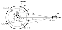
- FIG. 11 is a view showing parameters when the sensor 112 reaches each measurement points resulting from the rotation of the moving robot 100 .
- the rotational angle at each measurement point is represented by an angle rotated from the initial directional angle ⁇ 0 .
- the coordinates are represented by x a , y a , and 0, the rotational angle is represented by ⁇ a , and the distance from the remote control 200 is represented by L a .
- the coordinates, rotational angle, and distance from the remote control 200 at the second and third measurement points p b and p c are represented by the same ways.
- the range error and the angular error are not more than 10 cm and 1 degree, so that an exemplary embodiment may be sufficiently practical when used indoors where the distance between the moving robot 100 and the remote control 200 is not too far.
- the computer readable code/instructions can be recorded in/on a medium/media in a variety of ways, with examples of the medium/media including magnetic storage media (e.g., floppy disks, hard disks, magnetic tapes, etc.), optical media (e.g., CD-ROMs, DVDs, etc.), magneto-optical media (e.g., floptical disks), and hardware storage devices (e.g., read only memory media, random access memory media, flash memories, etc.).
- the medium/media may also be a distributed network, so that the computer readable code/instructions are stored and executed in a distributed fashion.
- the computer readable code/instructions may be executed by one or more processors.
- the computer readable code/instructions may also be executed and/or embodied in at least one application specific integrated circuit (ASIC) or Field Programmable Gate Array (FPGA).
- ASIC application specific integrated circuit
- FPGA Field Programmable Gate Array
Abstract
Description
x a =x 0 +r·cos(θ0+θa)
y a =r·sin(θ0+θa)
x b =x 0 +r·cos(θ0+θb)
y b =r·sin(θ0+θb)
x c =x 0 +r·cos(θ0+θc)
y c =r·sin(θ0+θc) [Numerical Formula 2]
L a 2 =x a 2 +y a 2 +h 2
L b 2 =x b 2 +y b 2 +h 2
L c 2 =x c 2 +y c 2 +h 2 [Numerical Formula 3]
where, h is the height of the
| TABLE 1 | ||||||
| Error | 1 m | 2 m | 3 m | Average | ||
| Range Error (cm) | 7.667 | 14.57 | 3.14 | 8.46 | ||
| Angular Error (deg) | 0.910 | 1.12 | 0.94 | 0.98 | ||
Claims (27)
Applications Claiming Priority (2)
| Application Number | Priority Date | Filing Date | Title |
|---|---|---|---|
| KR1020060064054A KR100791383B1 (en) | 2006-07-07 | 2006-07-07 | Method for estimating relative position between moving robot and transmitter and apparatus thereof |
| KR10-2006-0064054 | 2006-07-07 |
Publications (2)
| Publication Number | Publication Date |
|---|---|
| US20080009974A1 US20080009974A1 (en) | 2008-01-10 |
| US8060256B2 true US8060256B2 (en) | 2011-11-15 |
Family
ID=38920046
Family Applications (1)
| Application Number | Title | Priority Date | Filing Date |
|---|---|---|---|
| US11/822,438 Active 2030-08-14 US8060256B2 (en) | 2006-07-07 | 2007-07-05 | Apparatus, method, and medium for localizing moving robot and transmitter |
Country Status (2)
| Country | Link |
|---|---|
| US (1) | US8060256B2 (en) |
| KR (1) | KR100791383B1 (en) |
Cited By (3)
| Publication number | Priority date | Publication date | Assignee | Title |
|---|---|---|---|---|
| US20100286825A1 (en) * | 2007-07-18 | 2010-11-11 | Ho-Seon Rew | Mobile robot and controlling method thereof |
| US20120086389A1 (en) * | 2010-10-11 | 2012-04-12 | Gary Li | Battery charger for mobile robotic vacuum cleaner |
| US20220130233A1 (en) * | 2018-10-22 | 2022-04-28 | Lazer Safe Pty Ltd | Wireless monitoring/control |
Families Citing this family (12)
| Publication number | Priority date | Publication date | Assignee | Title |
|---|---|---|---|---|
| KR100980675B1 (en) | 2008-06-11 | 2010-09-07 | 삼성중공업 주식회사 | Method and apparatus for location discriminating of mobile object |
| KR101189568B1 (en) * | 2010-12-01 | 2012-10-11 | 현대자동차주식회사 | Automated system and method for steering wheel leveler |
| KR101339899B1 (en) | 2011-11-17 | 2013-12-10 | 재단법인대구경북과학기술원 | method for robot self-localization based on smart phone platform |
| JP2013167484A (en) * | 2012-02-14 | 2013-08-29 | Egenpower Inc | Positioning system of cleaning apparatus |
| EP2629114A1 (en) * | 2012-02-17 | 2013-08-21 | Egenpower Inc. | Positioning system for detecting position of cleansing device |
| CN105157697B (en) * | 2015-07-31 | 2017-05-17 | 天津大学 | Indoor mobile robot pose measurement system and measurement method based on optoelectronic scanning |
| CN106444772B (en) * | 2016-10-25 | 2019-05-03 | 北京京东尚科信息技术有限公司 | Automatic guide vehicle train rudder angle automatic adjusting method, device and automatic guide vehicle |
| CN106625584A (en) * | 2016-11-28 | 2017-05-10 | 清华大学 | Robot for astronaut space work and based on cable parallel configuration |
| CN107271961A (en) * | 2017-06-02 | 2017-10-20 | 深圳市优必选科技有限公司 | A kind of robot and its distance-finding method, robot charging system |
| CN109657198B (en) * | 2017-10-11 | 2023-01-06 | 杭州海康机器人股份有限公司 | Robot calibration method and device and computer readable storage medium |
| KR101937689B1 (en) * | 2017-11-24 | 2019-04-11 | (주)유프랜드 | Worker-following Control Algorithm Applied Moving Device |
| CN111044034A (en) * | 2019-12-04 | 2020-04-21 | 浙江大学 | Positioning and orienting method for mobile robot in fixed operation area |
Citations (19)
| Publication number | Priority date | Publication date | Assignee | Title |
|---|---|---|---|---|
| US5446356A (en) * | 1993-09-09 | 1995-08-29 | Samsung Electronics Co., Ltd. | Mobile robot |
| US5491670A (en) * | 1993-01-21 | 1996-02-13 | Weber; T. Jerome | System and method for sonic positioning |
| JP2000056006A (en) | 1998-08-14 | 2000-02-25 | Minolta Co Ltd | Position recognizing device for mobile |
| US6459955B1 (en) * | 1999-11-18 | 2002-10-01 | The Procter & Gamble Company | Home cleaning robot |
| KR200321249Y1 (en) | 2003-04-19 | 2003-07-28 | 오토사이언스(주) | Wireless remote control wireless vacuum cleaner |
| JP2003262520A (en) | 2002-03-08 | 2003-09-19 | Hitachi Ltd | Direction detecting device and self-traveling cleaner loaded with it |
| KR20040023421A (en) | 2002-09-11 | 2004-03-18 | 엘지전자 주식회사 | Cleaning control method and apparatus for vacuum cleaner using remote controller |
| US6748297B2 (en) * | 2002-10-31 | 2004-06-08 | Samsung Gwangju Electronics Co., Ltd. | Robot cleaner system having external charging apparatus and method for docking with the charging apparatus |
| US20040158354A1 (en) * | 2002-12-30 | 2004-08-12 | Samsung Electronics Co., Ltd. | Robot localization system |
| US20040199301A1 (en) * | 2003-01-23 | 2004-10-07 | Lg Electronics Inc. | Position information recognition apparatus for cleaning robot |
| KR20040087176A (en) | 2003-04-04 | 2004-10-13 | 엘지전자 주식회사 | Auto charge system and return method for robot cleaner |
| US20050010330A1 (en) * | 2003-07-11 | 2005-01-13 | Shai Abramson | Autonomous machine for docking with a docking station and method for docking |
| KR20050011568A (en) | 2003-07-23 | 2005-01-29 | 엘지전자 주식회사 | Position detection apparatus and method for mobile robot |
| US6868307B2 (en) * | 2002-10-31 | 2005-03-15 | Samsung Gwangju Electronics Co., Ltd. | Robot cleaner, robot cleaning system and method for controlling the same |
| US20050171636A1 (en) * | 2004-01-30 | 2005-08-04 | Funai Electric Co., Ltd. | Autonomous mobile robot cleaner system |
| US20050267631A1 (en) * | 2004-05-14 | 2005-12-01 | Ju-Sang Lee | Mobile robot and system and method of compensating for path diversions |
| KR20060011552A (en) | 2004-07-30 | 2006-02-03 | 엘지전자 주식회사 | Mobile robot and his moving control method |
| KR100575706B1 (en) | 2004-11-11 | 2006-05-03 | 엘지전자 주식회사 | Charge return system and method for robot cleaner |
| KR20060068968A (en) | 2004-12-17 | 2006-06-21 | 삼성전자주식회사 | Robot system |
-
2006
- 2006-07-07 KR KR1020060064054A patent/KR100791383B1/en active IP Right Grant
-
2007
- 2007-07-05 US US11/822,438 patent/US8060256B2/en active Active
Patent Citations (20)
| Publication number | Priority date | Publication date | Assignee | Title |
|---|---|---|---|---|
| US5491670A (en) * | 1993-01-21 | 1996-02-13 | Weber; T. Jerome | System and method for sonic positioning |
| US5446356A (en) * | 1993-09-09 | 1995-08-29 | Samsung Electronics Co., Ltd. | Mobile robot |
| JP2000056006A (en) | 1998-08-14 | 2000-02-25 | Minolta Co Ltd | Position recognizing device for mobile |
| US6459955B1 (en) * | 1999-11-18 | 2002-10-01 | The Procter & Gamble Company | Home cleaning robot |
| JP2003262520A (en) | 2002-03-08 | 2003-09-19 | Hitachi Ltd | Direction detecting device and self-traveling cleaner loaded with it |
| KR20040023421A (en) | 2002-09-11 | 2004-03-18 | 엘지전자 주식회사 | Cleaning control method and apparatus for vacuum cleaner using remote controller |
| US6868307B2 (en) * | 2002-10-31 | 2005-03-15 | Samsung Gwangju Electronics Co., Ltd. | Robot cleaner, robot cleaning system and method for controlling the same |
| US6748297B2 (en) * | 2002-10-31 | 2004-06-08 | Samsung Gwangju Electronics Co., Ltd. | Robot cleaner system having external charging apparatus and method for docking with the charging apparatus |
| US20040158354A1 (en) * | 2002-12-30 | 2004-08-12 | Samsung Electronics Co., Ltd. | Robot localization system |
| US20040199301A1 (en) * | 2003-01-23 | 2004-10-07 | Lg Electronics Inc. | Position information recognition apparatus for cleaning robot |
| KR20040087176A (en) | 2003-04-04 | 2004-10-13 | 엘지전자 주식회사 | Auto charge system and return method for robot cleaner |
| KR200321249Y1 (en) | 2003-04-19 | 2003-07-28 | 오토사이언스(주) | Wireless remote control wireless vacuum cleaner |
| US20050010330A1 (en) * | 2003-07-11 | 2005-01-13 | Shai Abramson | Autonomous machine for docking with a docking station and method for docking |
| KR20050011568A (en) | 2003-07-23 | 2005-01-29 | 엘지전자 주식회사 | Position detection apparatus and method for mobile robot |
| US20050171636A1 (en) * | 2004-01-30 | 2005-08-04 | Funai Electric Co., Ltd. | Autonomous mobile robot cleaner system |
| JP2005211359A (en) | 2004-01-30 | 2005-08-11 | Funai Electric Co Ltd | Autonomous traveling robot cleaner system |
| US20050267631A1 (en) * | 2004-05-14 | 2005-12-01 | Ju-Sang Lee | Mobile robot and system and method of compensating for path diversions |
| KR20060011552A (en) | 2004-07-30 | 2006-02-03 | 엘지전자 주식회사 | Mobile robot and his moving control method |
| KR100575706B1 (en) | 2004-11-11 | 2006-05-03 | 엘지전자 주식회사 | Charge return system and method for robot cleaner |
| KR20060068968A (en) | 2004-12-17 | 2006-06-21 | 삼성전자주식회사 | Robot system |
Non-Patent Citations (3)
| Title |
|---|
| Kim et al., Robot Localization using Ultrasonic Sensors, IEEE, proceedings of IEEE/RSJ International Conference on Intelligent Robots and Systems, Sep. 28-Oct. 2, 2004, Sendal, Japan, pp. 3762-3766. * |
| Korean Intellectual Property Office Notice of Examination issued Apr. 30, 2007 in corresponding Korean Patent No. 10-2006-0064054. |
| Notice of Allowance dated Oct. 25, 2007, issued in corresponding Korean Patent Application No. 10-2006-0064056. |
Cited By (6)
| Publication number | Priority date | Publication date | Assignee | Title |
|---|---|---|---|---|
| US20100286825A1 (en) * | 2007-07-18 | 2010-11-11 | Ho-Seon Rew | Mobile robot and controlling method thereof |
| US8489234B2 (en) * | 2007-07-18 | 2013-07-16 | Lg Electronics Inc. | Mobile robot and controlling method thereof |
| US20120086389A1 (en) * | 2010-10-11 | 2012-04-12 | Gary Li | Battery charger for mobile robotic vacuum cleaner |
| US8680816B2 (en) * | 2010-10-11 | 2014-03-25 | Egenpower Inc. | Battery charger for mobile robotic vacuum cleaner |
| US20220130233A1 (en) * | 2018-10-22 | 2022-04-28 | Lazer Safe Pty Ltd | Wireless monitoring/control |
| US11545028B2 (en) * | 2018-10-22 | 2023-01-03 | Lazer Safe Pty Ltd | Wireless monitoring/control |
Also Published As
| Publication number | Publication date |
|---|---|
| US20080009974A1 (en) | 2008-01-10 |
| KR100791383B1 (en) | 2008-01-07 |
Similar Documents
| Publication | Publication Date | Title |
|---|---|---|
| US8060256B2 (en) | Apparatus, method, and medium for localizing moving robot and transmitter | |
| KR101297388B1 (en) | Moving apparatus and method for compensating position | |
| US7970491B2 (en) | Robot localization system | |
| US9222801B2 (en) | Apparatus and method for correcting error of gyro sensor in mobile robot | |
| US8306684B2 (en) | Autonomous moving apparatus | |
| Tsai | A localization system of a mobile robot by fusing dead-reckoning and ultrasonic measurements | |
| Bonnifait et al. | Design and experimental validation of an odometric and goniometric localization system for outdoor robot vehicles | |
| US6176837B1 (en) | Motion tracking system | |
| US20180067503A1 (en) | Orientation control method for drone | |
| US20080154429A1 (en) | Apparatus, method, and medium for distinguishing the movement state of mobile robot | |
| US20060238156A1 (en) | Self-moving robot capable of correcting movement errors and method for correcting movement errors of the same | |
| Nasir et al. | Autonomous mobile robot localization using Kalman filter | |
| Tsai et al. | Multisensor 3D posture determination of a mobile robot using inertial and ultrasonic sensors | |
| Cechowicz et al. | Indoor vehicle tracking with a smart MEMS sensor | |
| KR100962674B1 (en) | The method for estimating location of moble robot and mobile robot thereof | |
| Komoriya et al. | A method of autonomous locomotion for mobile robots | |
| Márton et al. | Calibration and measurement processing for ultrasonic indoor mobile robot localization systems | |
| Gokaraju et al. | Maneuvering of Autonomous Vehicles through Proportional, Integral and Derivative Control Variables | |
| KR101519431B1 (en) | Azimuth providing apparatus | |
| Panich et al. | Sensor fusion techniques in navigation application for mobile robot | |
| Shuvo et al. | Sonar sensor virtualization for object detection and localization | |
| JPH05257530A (en) | Method and device for correcting bearing and position of moving robot | |
| JPH0412433B2 (en) | ||
| Casali | Real-Time State Estimation of a Two-Wheeled Inverted Pendulum Robot for Motion and Navigation Control | |
| Nitulescu | Localization of Mobile Robots. Theoretical Aspects |
Legal Events
| Date | Code | Title | Description |
|---|---|---|---|
| AS | Assignment |
Owner name: SAMSUNG ELECTRONICS CO., LTD., KOREA, REPUBLIC OF Free format text: ASSIGNMENT OF ASSIGNORS INTEREST;ASSIGNORS:KONG, DONG-GEON;BANG, SEOK-WON;MYEONG, HYEON;REEL/FRAME:019578/0785 Effective date: 20070703 |
|
| STCF | Information on status: patent grant |
Free format text: PATENTED CASE |
|
| FEPP | Fee payment procedure |
Free format text: PAYOR NUMBER ASSIGNED (ORIGINAL EVENT CODE: ASPN); ENTITY STATUS OF PATENT OWNER: LARGE ENTITY |
|
| CC | Certificate of correction | ||
| FPAY | Fee payment |
Year of fee payment: 4 |
|
| MAFP | Maintenance fee payment |
Free format text: PAYMENT OF MAINTENANCE FEE, 8TH YEAR, LARGE ENTITY (ORIGINAL EVENT CODE: M1552); ENTITY STATUS OF PATENT OWNER: LARGE ENTITY Year of fee payment: 8 |
|
| MAFP | Maintenance fee payment |
Free format text: PAYMENT OF MAINTENANCE FEE, 12TH YEAR, LARGE ENTITY (ORIGINAL EVENT CODE: M1553); ENTITY STATUS OF PATENT OWNER: LARGE ENTITY Year of fee payment: 12 |