US8057926B2 - Perpendicular magnetic recording medium - Google Patents
Perpendicular magnetic recording medium Download PDFInfo
- Publication number
- US8057926B2 US8057926B2 US12/666,561 US66656108A US8057926B2 US 8057926 B2 US8057926 B2 US 8057926B2 US 66656108 A US66656108 A US 66656108A US 8057926 B2 US8057926 B2 US 8057926B2
- Authority
- US
- United States
- Prior art keywords
- magnetic recording
- magnetic
- recording layer
- layer
- oxide
- Prior art date
- Legal status (The legal status is an assumption and is not a legal conclusion. Google has not performed a legal analysis and makes no representation as to the accuracy of the status listed.)
- Active
Links
- 230000005291 magnetic effect Effects 0.000 title claims abstract description 506
- 238000005549 size reduction Methods 0.000 claims abstract description 47
- VYPSYNLAJGMNEJ-UHFFFAOYSA-N Silicium dioxide Chemical group O=[Si]=O VYPSYNLAJGMNEJ-UHFFFAOYSA-N 0.000 claims description 161
- 229910052681 coesite Inorganic materials 0.000 claims description 83
- 229910052906 cristobalite Inorganic materials 0.000 claims description 83
- 239000000377 silicon dioxide Substances 0.000 claims description 83
- 229910052682 stishovite Inorganic materials 0.000 claims description 83
- 229910052905 tridymite Inorganic materials 0.000 claims description 83
- GWEVSGVZZGPLCZ-UHFFFAOYSA-N Titan oxide Chemical group O=[Ti]=O GWEVSGVZZGPLCZ-UHFFFAOYSA-N 0.000 claims description 73
- 239000002131 composite material Substances 0.000 claims description 63
- 230000001737 promoting effect Effects 0.000 claims description 36
- 239000000758 substrate Substances 0.000 claims description 20
- 229910052719 titanium Inorganic materials 0.000 claims description 5
- 230000005294 ferromagnetic effect Effects 0.000 claims description 3
- 230000006872 improvement Effects 0.000 abstract description 24
- 238000002955 isolation Methods 0.000 abstract description 22
- 239000010410 layer Substances 0.000 description 342
- OGIDPMRJRNCKJF-UHFFFAOYSA-N titanium oxide Inorganic materials [Ti]=O OGIDPMRJRNCKJF-UHFFFAOYSA-N 0.000 description 68
- QDOXWKRWXJOMAK-UHFFFAOYSA-N dichromium trioxide Chemical compound O=[Cr]O[Cr]=O QDOXWKRWXJOMAK-UHFFFAOYSA-N 0.000 description 51
- 239000013078 crystal Substances 0.000 description 49
- 230000000052 comparative effect Effects 0.000 description 47
- 239000000126 substance Substances 0.000 description 31
- 239000000203 mixture Substances 0.000 description 21
- 239000010408 film Substances 0.000 description 16
- 239000012790 adhesive layer Substances 0.000 description 15
- 239000002356 single layer Substances 0.000 description 13
- 238000010586 diagram Methods 0.000 description 12
- 239000000463 material Substances 0.000 description 12
- 238000006243 chemical reaction Methods 0.000 description 11
- 239000011651 chromium Substances 0.000 description 10
- 239000011241 protective layer Substances 0.000 description 10
- 230000009467 reduction Effects 0.000 description 10
- 229910019222 CoCrPt Inorganic materials 0.000 description 9
- 229910045601 alloy Inorganic materials 0.000 description 9
- 239000000956 alloy Substances 0.000 description 9
- 238000005204 segregation Methods 0.000 description 9
- 238000011156 evaluation Methods 0.000 description 7
- 230000006870 function Effects 0.000 description 7
- 239000011521 glass Substances 0.000 description 7
- 229910020442 SiO2—TiO2 Inorganic materials 0.000 description 6
- 230000008901 benefit Effects 0.000 description 6
- 230000001050 lubricating effect Effects 0.000 description 6
- BPUBBGLMJRNUCC-UHFFFAOYSA-N oxygen(2-);tantalum(5+) Chemical compound [O-2].[O-2].[O-2].[O-2].[O-2].[Ta+5].[Ta+5] BPUBBGLMJRNUCC-UHFFFAOYSA-N 0.000 description 6
- KDLHZDBZIXYQEI-UHFFFAOYSA-N palladium Substances [Pd] KDLHZDBZIXYQEI-UHFFFAOYSA-N 0.000 description 6
- 230000002829 reductive effect Effects 0.000 description 6
- 230000005415 magnetization Effects 0.000 description 5
- 238000000034 method Methods 0.000 description 5
- RVTZCBVAJQQJTK-UHFFFAOYSA-N oxygen(2-);zirconium(4+) Chemical compound [O-2].[O-2].[Zr+4] RVTZCBVAJQQJTK-UHFFFAOYSA-N 0.000 description 5
- 125000006850 spacer group Chemical group 0.000 description 5
- 229910001936 tantalum oxide Inorganic materials 0.000 description 5
- 230000007704 transition Effects 0.000 description 5
- 229910001928 zirconium oxide Inorganic materials 0.000 description 5
- IJGRMHOSHXDMSA-UHFFFAOYSA-N Atomic nitrogen Chemical compound N#N IJGRMHOSHXDMSA-UHFFFAOYSA-N 0.000 description 4
- CURLTUGMZLYLDI-UHFFFAOYSA-N Carbon dioxide Chemical compound O=C=O CURLTUGMZLYLDI-UHFFFAOYSA-N 0.000 description 4
- 238000005229 chemical vapour deposition Methods 0.000 description 4
- 230000003247 decreasing effect Effects 0.000 description 4
- 238000000151 deposition Methods 0.000 description 4
- 239000007789 gas Substances 0.000 description 4
- 230000003993 interaction Effects 0.000 description 4
- 239000010702 perfluoropolyether Substances 0.000 description 4
- OKTJSMMVPCPJKN-UHFFFAOYSA-N Carbon Chemical compound [C] OKTJSMMVPCPJKN-UHFFFAOYSA-N 0.000 description 3
- WGLPBDUCMAPZCE-UHFFFAOYSA-N Trioxochromium Chemical compound O=[Cr](=O)=O WGLPBDUCMAPZCE-UHFFFAOYSA-N 0.000 description 3
- 239000005354 aluminosilicate glass Substances 0.000 description 3
- 229910052799 carbon Inorganic materials 0.000 description 3
- 229910000423 chromium oxide Inorganic materials 0.000 description 3
- 230000008878 coupling Effects 0.000 description 3
- 238000010168 coupling process Methods 0.000 description 3
- 238000005859 coupling reaction Methods 0.000 description 3
- 238000003618 dip coating Methods 0.000 description 3
- 230000000694 effects Effects 0.000 description 3
- 238000004519 manufacturing process Methods 0.000 description 3
- 229910052763 palladium Inorganic materials 0.000 description 3
- 239000010409 thin film Substances 0.000 description 3
- UGFAIRIUMAVXCW-UHFFFAOYSA-N Carbon monoxide Chemical compound [O+]#[C-] UGFAIRIUMAVXCW-UHFFFAOYSA-N 0.000 description 2
- 229910018979 CoPt Inorganic materials 0.000 description 2
- 229910003271 Ni-Fe Inorganic materials 0.000 description 2
- QVGXLLKOCUKJST-UHFFFAOYSA-N atomic oxygen Chemical compound [O] QVGXLLKOCUKJST-UHFFFAOYSA-N 0.000 description 2
- 229910002092 carbon dioxide Inorganic materials 0.000 description 2
- 239000001569 carbon dioxide Substances 0.000 description 2
- 229910002091 carbon monoxide Inorganic materials 0.000 description 2
- 229910052804 chromium Inorganic materials 0.000 description 2
- 230000008021 deposition Effects 0.000 description 2
- 239000010931 gold Substances 0.000 description 2
- 238000001755 magnetron sputter deposition Methods 0.000 description 2
- 229910052751 metal Inorganic materials 0.000 description 2
- 239000002184 metal Substances 0.000 description 2
- 238000012986 modification Methods 0.000 description 2
- 230000004048 modification Effects 0.000 description 2
- 229910052757 nitrogen Inorganic materials 0.000 description 2
- 230000006911 nucleation Effects 0.000 description 2
- 238000010899 nucleation Methods 0.000 description 2
- 229910052760 oxygen Inorganic materials 0.000 description 2
- 239000001301 oxygen Substances 0.000 description 2
- 229910052697 platinum Inorganic materials 0.000 description 2
- 239000010948 rhodium Substances 0.000 description 2
- 239000006017 silicate glass-ceramic Substances 0.000 description 2
- 229910052814 silicon oxide Inorganic materials 0.000 description 2
- 238000004544 sputter deposition Methods 0.000 description 2
- 229910052715 tantalum Inorganic materials 0.000 description 2
- 239000010936 titanium Substances 0.000 description 2
- 229910011255 B2O3 Inorganic materials 0.000 description 1
- VYZAMTAEIAYCRO-UHFFFAOYSA-N Chromium Chemical compound [Cr] VYZAMTAEIAYCRO-UHFFFAOYSA-N 0.000 description 1
- 229910020598 Co Fe Inorganic materials 0.000 description 1
- 229910000531 Co alloy Inorganic materials 0.000 description 1
- 229910002519 Co-Fe Inorganic materials 0.000 description 1
- -1 CoCrFeB Inorganic materials 0.000 description 1
- CDBYLPFSWZWCQE-UHFFFAOYSA-L Sodium Carbonate Chemical compound [Na+].[Na+].[O-]C([O-])=O CDBYLPFSWZWCQE-UHFFFAOYSA-L 0.000 description 1
- 239000005407 aluminoborosilicate glass Substances 0.000 description 1
- 229910000808 amorphous metal alloy Inorganic materials 0.000 description 1
- 230000005316 antiferromagnetic exchange Effects 0.000 description 1
- 230000015572 biosynthetic process Effects 0.000 description 1
- 239000005388 borosilicate glass Substances 0.000 description 1
- 230000015556 catabolic process Effects 0.000 description 1
- 238000003426 chemical strengthening reaction Methods 0.000 description 1
- 239000005345 chemically strengthened glass Substances 0.000 description 1
- IAQWMWUKBQPOIY-UHFFFAOYSA-N chromium(4+);oxygen(2-) Chemical compound [O-2].[O-2].[Cr+4] IAQWMWUKBQPOIY-UHFFFAOYSA-N 0.000 description 1
- 229910017052 cobalt Inorganic materials 0.000 description 1
- 239000010941 cobalt Substances 0.000 description 1
- GUTLYIVDDKVIGB-UHFFFAOYSA-N cobalt atom Chemical compound [Co] GUTLYIVDDKVIGB-UHFFFAOYSA-N 0.000 description 1
- 229910052802 copper Inorganic materials 0.000 description 1
- 230000007547 defect Effects 0.000 description 1
- 238000006731 degradation reaction Methods 0.000 description 1
- JKWMSGQKBLHBQQ-UHFFFAOYSA-N diboron trioxide Chemical compound O=BOB=O JKWMSGQKBLHBQQ-UHFFFAOYSA-N 0.000 description 1
- 238000002474 experimental method Methods 0.000 description 1
- 230000004907 flux Effects 0.000 description 1
- PCHJSUWPFVWCPO-UHFFFAOYSA-N gold Chemical compound [Au] PCHJSUWPFVWCPO-UHFFFAOYSA-N 0.000 description 1
- 229910052737 gold Inorganic materials 0.000 description 1
- 238000000227 grinding Methods 0.000 description 1
- 229910052735 hafnium Inorganic materials 0.000 description 1
- 230000010365 information processing Effects 0.000 description 1
- 230000002401 inhibitory effect Effects 0.000 description 1
- 150000002500 ions Chemical class 0.000 description 1
- 229910052741 iridium Inorganic materials 0.000 description 1
- GKOZUEZYRPOHIO-UHFFFAOYSA-N iridium atom Chemical compound [Ir] GKOZUEZYRPOHIO-UHFFFAOYSA-N 0.000 description 1
- JEIPFZHSYJVQDO-UHFFFAOYSA-N iron(III) oxide Inorganic materials O=[Fe]O[Fe]=O JEIPFZHSYJVQDO-UHFFFAOYSA-N 0.000 description 1
- 229910001004 magnetic alloy Inorganic materials 0.000 description 1
- 239000000696 magnetic material Substances 0.000 description 1
- 238000005259 measurement Methods 0.000 description 1
- 239000005300 metallic glass Substances 0.000 description 1
- 239000013081 microcrystal Substances 0.000 description 1
- 229910052750 molybdenum Inorganic materials 0.000 description 1
- 229910052759 nickel Inorganic materials 0.000 description 1
- 229910052758 niobium Inorganic materials 0.000 description 1
- 150000004767 nitrides Chemical class 0.000 description 1
- 125000004433 nitrogen atom Chemical group N* 0.000 description 1
- 238000005457 optimization Methods 0.000 description 1
- 229910052762 osmium Inorganic materials 0.000 description 1
- SYQBFIAQOQZEGI-UHFFFAOYSA-N osmium atom Chemical compound [Os] SYQBFIAQOQZEGI-UHFFFAOYSA-N 0.000 description 1
- SIWVEOZUMHYXCS-UHFFFAOYSA-N oxo(oxoyttriooxy)yttrium Chemical compound O=[Y]O[Y]=O SIWVEOZUMHYXCS-UHFFFAOYSA-N 0.000 description 1
- 238000005498 polishing Methods 0.000 description 1
- 238000003825 pressing Methods 0.000 description 1
- 229910052703 rhodium Inorganic materials 0.000 description 1
- MHOVAHRLVXNVSD-UHFFFAOYSA-N rhodium atom Chemical compound [Rh] MHOVAHRLVXNVSD-UHFFFAOYSA-N 0.000 description 1
- 229910052709 silver Inorganic materials 0.000 description 1
- 239000004332 silver Substances 0.000 description 1
- 239000005361 soda-lime glass Substances 0.000 description 1
- 239000007787 solid Substances 0.000 description 1
- 238000003860 storage Methods 0.000 description 1
- 239000002344 surface layer Substances 0.000 description 1
- 229910052721 tungsten Inorganic materials 0.000 description 1
- 229910052720 vanadium Inorganic materials 0.000 description 1
- 229910052726 zirconium Inorganic materials 0.000 description 1
Images


Classifications
-
- G—PHYSICS
- G11—INFORMATION STORAGE
- G11B—INFORMATION STORAGE BASED ON RELATIVE MOVEMENT BETWEEN RECORD CARRIER AND TRANSDUCER
- G11B5/00—Recording by magnetisation or demagnetisation of a record carrier; Reproducing by magnetic means; Record carriers therefor
- G11B5/62—Record carriers characterised by the selection of the material
- G11B5/64—Record carriers characterised by the selection of the material comprising only the magnetic material without bonding agent
- G11B5/66—Record carriers characterised by the selection of the material comprising only the magnetic material without bonding agent the record carriers consisting of several layers
- G11B5/672—Record carriers characterised by the selection of the material comprising only the magnetic material without bonding agent the record carriers consisting of several layers having different compositions in a plurality of magnetic layers, e.g. layer compositions having differing elemental components or differing proportions of elements
-
- G—PHYSICS
- G11—INFORMATION STORAGE
- G11B—INFORMATION STORAGE BASED ON RELATIVE MOVEMENT BETWEEN RECORD CARRIER AND TRANSDUCER
- G11B5/00—Recording by magnetisation or demagnetisation of a record carrier; Reproducing by magnetic means; Record carriers therefor
- G11B5/84—Processes or apparatus specially adapted for manufacturing record carriers
- G11B5/855—Coating only part of a support with a magnetic layer
Definitions
- the present invention relates to a perpendicular magnetic recording medium mounted on a perpendicular magnetic recording type HDD (hard disk drive) or the like.
- perpendicular magnetic recording media of perpendicular magnetic recording type have been proposed in order to achieve a higher recording density of a magnetic recording medium used for an HDD or the like.
- a perpendicular magnetic recording type an axis of easy magnetization in a magnetic recording layer is arranged so as to be oriented in a direction perpendicular to a surface of a substrate.
- the perpendicular magnetic recording type is suitable to increase the recording density because it can suppress heat fluctuation phenomena as compared to a conventional longitudinal magnetic recording type.
- Non-patent Document 1 As a magnetic recording medium of perpendicular magnetic recording type, a CoCrPt—SiO 2 perpendicular magnetic recording medium has been proposed because it exhibits high thermal stability and excellent recording characteristics (see Non-patent Document 1).
- an oxide is used for non-magnetic grain boundaries (non-magnetic portions between magnetic grains).
- a size-reduction promoting layer having a non-magnetic granular structure (also referred to as an onset layer in some cases) in which SiO 2 is segregated at grain boundaries of a non-magnetic metal of CoCr may be provided below a magnetic recording layer (Patent Document 2).
- the size-reduction promoting layer is deposited on a Ru underlayer, which is a continuous crystal that is not isolated. Therefore, when a granular layer is to be formed on a Ru layer, segregation is not necessarily completed at an initial stage.
- the crystal orientation of bases of the granular columns is disordered, and the bases of the granular columns spread laterally such that they are coupled to each other.
- the disorder of the crystal orientation causes decrease of the SNR or the magnetic coercive force Hc.
- the coupling of the crystal grains also causes decrease of the SNR.
- the size-reduction promoting layer allows the bases of the granular portions to be formed of non-magnetic substance and thus serves to promote segregation and isolation of the granular portions (magnetic grains) in the magnetic recording layer even if the bases of granular portions have been coupled to each other.
- Magnetic recording media have been increased in recording density as described above. Further improvement in recording density has been demanded. Important elements for a higher recording density include various factors such as improvement of the magnetic coercive force Hc, the overwrite performance, improvement of the SNR (Signal-Noise Ratio), and reduction of the track width. Improvement of the SNR, which is important among others, is achieved mainly by noise reduction of a magnetic transition region in a magnetic recording layer. Noise reduction requires improvement in crystal orientation of the magnetic recording layer, reduction of the grain diameter of magnetic grains, and isolation of the magnetic grains. Specifically, for increasing the recording density of a medium, it is desired to uniformize and reduce the grain diameter of magnetic grains and also to maintain a segregation state in which individual magnetic grains are magnetically decoupled.
- improvement of the magnetic coercive force Hc is achieved by optimization of the materials or the crystal orientation of a magnetic layer and an underlayer, the film arrangement, and the like.
- Improvement of the SNR is achieved mainly by noise reduction of a magnetic transition region in a magnetic recording layer.
- a Co-based perpendicular magnetic recording layer particularly a CoPt-based perpendicular magnetic recording layer, is suitable because it has a high magnetic coercive force (Hc) and can reduce a reversed domain nucleation magnetic field (Hn) to be a small value less than zero so as to improve resistance to heat fluctuation and to have a high SNR.
- Hc magnetic coercive force
- Hn reversed domain nucleation magnetic field
- Cr can be segregated at grain boundary portions of magnetic grains. Therefore, magnetic grains can be isolated such that the exchange interaction is blocked.
- the Co-based perpendicular magnetic recording layer is conducive to increase of the recording density.
- Reduction in size of magnetic grains and isolation of magnetic grains are influenced by the thickness of an oxide in the horizontal direction (longitudinal direction) that has been segregated at grain boundaries. If the amount of oxide is increased, the SNR is improved at a high recording density. If the amount of oxide is excessively increased, the perpendicular magnetic anisotropy is deteriorated, resulting in problems of degradation in thermal stability and increase of noise. In other words, while it is effective to contain an oxide at grain boundaries, the amount of oxide that can be contained has a limitation. Thus, limits are put on reduction in size and improvement of isolation.
- An object of the present invention is to provide a perpendicular magnetic recording medium capable of further increasing a recording density by increasing magnetostatic characteristics (the magnetic coercive force Hc in particular) and increasing electromagnetic conversion characteristics (the SNR in particular).
- the inventors For the purpose of size reduction and isolation of magnetic grains, the inventors have examined oxides that form grain boundaries. The inventors have attracted attention to the fact that effects of an oxide differ depending not only upon the amount of the oxide, but also upon the kind of the oxide. The inventors have diligently studied effects depending upon the kind of an oxide and have found that SiO 2 tends to promote size reduction of magnetic grains and that TiO 2 tends to improve electromagnetic conversion characteristics (the SNR in particular).
- oxides have different characteristics.
- An appropriate oxide can be selected for desired performance.
- those characteristics have both advantages and disadvantages. Any oxide does not necessarily meet demands for future increase in recording density.
- the inventors have examined whether to simultaneously exhibit characteristics of a plurality of oxides and have found that those characteristics can be obtained without cancellation by properly using a plurality of oxides.
- a Ru underlayer has been provided for improving the crystal orientation of magnetic grains in a magnetic recording layer. Furthermore, a size-reduction promoting layer has been provided for eliminating influence of crystal growth at an initial stage. All of these assume that Co crystal grains epitaxially grow in a columnar shape from hcp crystals of Ru.
- the inventors have attracted attention to the fact that, when crystal grains grow through a plurality of layers including a size-reduction promoting layer, a first magnetic recording layer, and a second magnetic recording layer, they do not necessarily grow in a one-to-one relationship on the interfaces. Specifically, for example, if one column rises on two columns when an upper layer is deposited with a combination of new materials after movement to a next chamber, then isolation and size reduction of crystal grains become insufficient even though a granular structure has satisfactorily been formed in a lower layer.
- the inventors have found that crystal grains can grow in a one-to-one relationship with continuous growth of grain boundaries in addition to continuous growth of the crystal grains. Meanwhile, appropriate kinds of oxides that meet required functions should be selected for the size-reduction promoting layer, the first magnetic recording layer, and the second magnetic recording layer. The inventors have found that segregation and isolation of magnetic grains can further be promoted if grain boundaries can be made continuous even though different oxides are used and thus have completed the present invention.
- a typical configuration of a perpendicular magnetic recording medium according to the present invention is a perpendicular magnetic recording medium having a magnetic recording layer with a granular structure in which non-magnetic grain boundary portions are formed between magnetic grains that have grown continuously in a columnar shape. It is characterized that the grain boundary portions contain a plurality of kinds of oxides.
- a perpendicular magnetic recording medium that can have characteristics of a plurality of oxides, can reduce noise by further size reduction and isolation of magnetic grains in a magnetic recording layer, and can increase the recording density by improvement of the SNR.
- the plurality of kinds of oxides may include both of SiO 2 and TiO 2 .
- SiO 2 has characteristics of promoting size reduction and isolation of magnetic grains
- TiO 2 has characteristics of improving electromagnetic conversion characteristics (the SNR in particular).
- Those oxides are segregated in a composite manner at the grain boundaries of the magnetic recording layer. Thus, advantages of both oxides can be attained.
- the content of all of the plurality of kinds of oxides is preferably in a range of from 6 mol % to 12 mol %. Within the aforementioned range, advantages can be more than those of each single oxide of the contained oxides. Therefore, high magnetic coercive force and SNR can be obtained.
- a plurality of kinds of oxides may be contained at grain boundary portions of at least one of the magnetic recording layers. Furthermore, two or more of the plurality of magnetic recording layers or all of them may contain a plurality of kinds of oxides.
- Another typical configuration of the perpendicular magnetic recording medium according to the present invention is a perpendicular magnetic recording medium having at least a first magnetic recording layer and a second magnetic recording layer on a substrate in an order named.
- the first magnetic recording layer and the second magnetic recording layer are a ferromagnetic layer having a granular structure in which non-magnetic grain boundary portions are formed between magnetic grains that have grown continuously in a columnar shape.
- the grain boundary portions of the first magnetic recording layer and the second magnetic recording layer contain a plurality of kinds of oxides.
- a perpendicular magnetic recording medium that can have characteristics of a plurality of oxides, can increase magnetostatic characteristics (the magnetic coercive force Hc in particular) by further size reduction and isolation of magnetic grains in a magnetic recording layer, and can increase the recording density by improvement of electromagnetic conversion characteristics (the SNR in particular).
- This configuration can improve the OW performance with maintaining the magnetic coercive force Hc and a high SNR.
- the content of all of the plurality of kinds of oxides contained in the first magnetic recording layer or the second magnetic recording layer is preferably in a range of from 6 mol % to 12 mol %. Within the aforementioned range, advantages can be more than those of each single oxide of the contained oxides.
- the plurality of kinds of oxides can be selected from among SiO 2 , TiO 2 , CrO 2 , Cr 2 O 3 , ZrO 2 , and Ta 2 O 5 .
- the oxides may be a substance that can form grain boundary portions around magnetic grains so as to suppress or block the exchange interaction between the magnetic grains. Particularly, it is preferable to contain both SiO 2 and TiO 2 .
- For the first magnetic recording layer it is preferable to use one of combinations including Cr 2 O 3 +SiO 2 , Cr 2 O 3 +TiO 2 , and SiO 2 +TiO 2 .
- SiO 2 has characteristics of promoting size reduction and isolation of magnetic grains
- TiO 2 has characteristics of improving electromagnetic conversion characteristics (the SNR in particular). Those oxides are segregated in a composite manner at the grain boundaries of the magnetic recording layer. Thus, advantages of both oxides can be attained.
- the content of all of the plurality of kinds of oxides contained in the first magnetic recording layer is in a range of from 5 mol % to 8 mol %, and A ⁇ B where the content of all of the plurality of kinds of oxides contained in the first magnetic recording layer is defined by A mol %, and the content of all of the plurality of kinds of oxides contained in the second magnetic recording layer is defined by B mol %.
- the magnetic coercive force Hc tends to decrease when the content of all oxides in the first magnetic recording layer is excessively large or is excessively small. Within the aforementioned range, a high magnetic coercive force Hc can be obtained. Within the aforementioned range, the magnetic coercive force Hc has the maximum value when the content of all oxides in the second magnetic recording layer is 10 mol %.
- Still another typical configuration of a perpendicular magnetic recording medium has at least: a size-reduction promoting layer having a granular structure in which grain boundary portions containing a first oxide are formed between non-magnetic grains that have grown continuously in a columnar shape and reducing a size of magnetic grains of a magnetic recording layer; a first magnetic recording layer having a granular structure in which grain boundary portions containing the first oxide and a second oxide are formed between magnetic grains that have grown continuously in a columnar shape; and a second magnetic recording layer having a granular structure in which grain boundary portions containing the second oxide are formed between magnetic grains that have grown continuously in a columnar shape, on a substrate in an order named.
- the first oxide or the second oxide may be selected from among SiO 2 , TiO 2 , CrO 2 , Cr 2 O 3 , ZrO 2 , and Ta 2 O 5 .
- the oxides may be a substance that can form grain boundary portions around magnetic grains so as to suppress or block the exchange interaction between the magnetic grains.
- the first oxide may be SiO 2
- the second oxide may be TiO 2 . It is preferable to use SiO 2 for the size-reduction promoting layer because SiO 2 promotes size reduction. It is preferable to use TiO 2 for the second magnetic recording layer because a high SNR can be obtained.
- the recording density can further be increased by increasing magnetostatic characteristics (the magnetic coercive force Hc in particular) and increasing electromagnetic conversion characteristics (the SNR in particular).
- FIG. 1 is a diagram explanatory of an arrangement of a perpendicular magnetic recording medium according to a first embodiment.
- FIG. 2 is a diagram showing an example of an arrangement of the perpendicular magnetic recording medium according to the first embodiment.
- FIG. 3 is a graph showing relationship between a mixture ratio of an oxide or a composite oxide and an SNR in Example and Comparative Examples.
- FIG. 4 is a table showing the SNR and the magnetic coercive force Hc in a case where the content of a composite oxide was varied as a whole.
- FIG. 5 is a table showing evaluation results of heat fluctuation characteristics of CoCrPt—TiO 2 (single oxide) and CoCrPt—SiO 2 —TiO 2 (composite oxide).
- FIG. 6 is a diagram showing an example of an arrangement of a perpendicular magnetic recording medium according to a second embodiment.
- FIG. 7 is a graph showing relationship between the magnetic coercive force Hc and the SNR in Example and Comparative Examples.
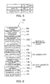
- FIG. 8 is a table showing the magnetic coercive force Hc and the SNR in cases where the total amounts of oxides contained in first and second magnetic recording layers 122 b were varied.
- FIG. 9 is a graph showing the magnetic coercive force Hc in cases where the total amount of oxides contained in the first magnetic recording layer was varied while the amount of oxides in the second magnetic recording layer was fixed at 10 mol %.
- FIG. 10 is a table showing the SNR, the magnetic coercive force Hc, and the overwrite performance when the composition of non-magnetic substance was varied.
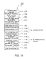
- FIG. 11 is a diagram showing an arrangement in which a magnetic recording layer is formed of a single layer.
- FIG. 12 is a diagram showing an example of an arrangement of a perpendicular magnetic recording medium according to a third embodiment.
- FIG. 13 is a table showing the compositions of a size-reduction promoting layer, a first magnetic recording layer, and a second magnetic recording layer that have been converted from the mol %-notation to the atomic %-notation.
- FIG. 14 is a graph showing the SNR [dB] with respect to the content of an oxide (mol %).
- FIG. 15 is a diagram showing the SNR [dB] with respect to the contents and the ratio of X2 and Y2 in the first magnetic recording layer.
- FIG. 16 is a table showing the magnetic coercive force Hc, the SNR, and the summarized evaluation in a case where the composition of non-magnetic substance was varied.
- a first embodiment of a method of manufacturing a perpendicular magnetic recording medium according to the present invention will be described below.
- the size, materials, and other specific values described in the following embodiments are mere examples for better understanding the present invention and do not limit the present invention unless otherwise explained.
- FIG. 1 is a diagram explanatory of an arrangement of a perpendicular magnetic recording medium 100 according to the embodiment.
- the perpendicular magnetic recording medium 100 shown in FIG. 1 has a disk substrate 110 , an adhesive layer 112 , a first soft magnetic layer 114 a , a spacer layer 114 b , a second soft magnetic layer 114 c , an orientation control layer 116 , a first underlayer 118 a , a second underlayer 118 b , a size-reduction promoting layer 120 , a first magnetic recording layer 122 a , a second magnetic recording layer 122 b , an auxiliary recording layer 124 , a medium protective layer 126 , and a lubricating layer 128 .
- the first soft magnetic layer 114 a , the spacer layer 114 b , and the second soft magnetic layer 114 c jointly form a soft magnetic layer 114 .
- the first underlayer 118 a and the second underlayer 118 b jointly form an underlayer 118 .
- the first magnetic recording layer 122 a and the second magnetic recording layer 122 b jointly form a magnetic recording layer 122 .
- a composite oxide a plurality of kinds of oxides (hereinafter referred to as a composite oxide) are contained in either one or both of the first magnetic recording layer 122 a and the second magnetic recording layer 122 b of the magnetic recording layer 122 , the composite oxide is segregated at non-magnetic grain boundaries.
- a glass disk into which an amorphous aluminosilicate glass is formed by direct pressing may be used as the disk substrate 110 .
- the kind, size, thickness, and the like of the glass substrate are not specifically limited.
- materials for the glass substrate include aluminosilicate glass, soda lime glass, soda aluminosilicate glass, aluminoborosilicate glass, borosilicate glass, quartz glass, chain silicate glass, and glass ceramic such as crystallized glass.
- This glass disk is sequentially subjected to grinding, polishing, and chemical strengthening so as to provide a non-magnetic smooth disk substrate 10 formed of a chemically strengthened glass disk.
- Layers from the adhesive layer 112 to the auxiliary recording layer 124 can be sequentially deposited on the disk substrate 110 by a DC magnetron sputtering method.
- the medium protective layer 126 can be deposited by a CVD method.
- the lubricating layer 128 can be formed by a dip coating method. It is preferable to use an in-line deposition method from the viewpoint of high productivity. The composition of each layer and a method of manufacturing each layer will be described below.
- the adhesive layer 112 is an amorphous underlayer and is formed in contact with the disk substrate 110 .
- the adhesive layer 112 has a function of increasing the peel strength of the soft magnetic layer 114 deposited on the adhesive layer 112 and the disk substrate 110 and a function of reducing the size of crystal grains in each of the layers deposited on the adhesive layer 112 and uniformizing the crystal grains.
- the disk substrate 110 is formed of amorphous glass, it is preferable to form the adhesive layer 112 of an amorphous alloy film so as to conform to a surface of the amorphous glass.
- the adhesive layer 112 can be selected from among a CrTi-based amorphous layer, a CoW-based amorphous layer, a CrW-based amorphous layer, a CrTa-based amorphous layer, and a CrNb-based amorphous layer.
- the CoW-based alloy film is preferable because it forms an amorphous metal film containing microcrystals.
- the adhesive layer 112 may include a single layer formed of a single material. Nevertheless, the adhesive layer 112 may be formed by stacking a plurality of layers. For example, a CoW layer or a CrW layer may be formed on a CrTi layer. It is preferable to sputter a material including carbon dioxide, carbon monoxide, nitrogen, or oxygen on the adhesive layer 112 or to expose a surface layer of the adhesive layer 112 to a gas including carbon dioxide, carbon monoxide, nitrogen, or oxygen.
- the soft magnetic layer 114 is a layer for forming a magnetic path temporarily at the time of recording in order to pass a magnetic flux through the recording layer in a perpendicular direction according to the perpendicular magnetic recording method.
- the soft magnetic layer 114 can be configured to have AFC (antiferro-magnetic exchange coupling) with interposing the non-magnetic spacer layer 114 b between the first soft magnetic layer 114 a and the second soft magnetic layer 114 c .
- AFC antiferro-magnetic exchange coupling
- a cobalt-based alloy such as CoTaZr, a Co—Fe-based alloy such as CoCrFeB, or a Ni—Fe-based alloy such as a multilayer structure of [Ni—Fe/Sn]n may be used for the first soft magnetic layer 114 a and the second soft magnetic layer 114 c.
- the orientation control layer 116 is a non-magnetic alloy layer.
- the orientation control layer 116 has a function of protecting the soft magnetic layer 114 and a function of orienting an axis of easy magnetization of a hexagonal close-packed structure (hcp structure) contained in the underlayer 118 , which is deposited on the orientation control layer 116 , toward a direction perpendicular to the disk. It is preferable to arrange the orientation control layer 116 such that the ( 111 ) surface of the face-centered cubic structure (fcc structure) or the ( 110 ) surface of the body-centered cubic structure (bcc structure) is parallel to the principal surface of the disk substrate 110 .
- the orientation control layer 116 may be arranged to mix those crystal structures and amorphous substance.
- a material of the orientation control layer may be selected from among Ni, Cu, Pt, Pd, Zr, Hf, Nb, and Ta.
- the orientation control layer may be an alloy containing such a metal as a principal component and one or more additional elements of Ti, V, Ta, Cr, Mo, and W.
- NiW, CuW, or CuCr may suitably be selected for the fcc structure
- Ta may suitably be selected for the bcc structure.
- the underlayer 118 has an hcp structure.
- the underlayer 118 has a function of allowing Co crystals of the magnetic recording layer 122 having an hcp structure to grow into a granular structure. Therefore, the orientation of the magnetic recording layer 122 can further be improved as the underlayer 18 has a higher crystal orientation, i.e., the (0001) surface of the crystals in the underlayer 118 is more parallel to the principal surface of the disk substrate 110 .
- a typical material of the underlayer is Ru. Additionally, the material of the underlayer can be selected from RuCr and RuCo. Ru has an hcp structure and also has lattice intervals of crystals that are close to those of Co. Therefore, Ru can favorably orient a magnetic recording layer containing Co as a principal component.
- a double layer structure of Ru can be formed by changing a gas pressure during sputtering. Specifically, when the second underlayer 118 b on an upper side of the underlayer 118 is to be formed, a gas pressure of Ar is changed so as to be higher than that for formation of the first underlayer 118 a on a lower side of the underlayer 118 . If a gas pressure is increased, free movement paths of sputtered plasma ions are shortened. Therefore, a deposition rate is lowered, so that the crystal orientation can be improved. Furthermore, a high pressure reduces the size of the crystal lattice.
- the crystal lattice of Ru is larger in size than that of Co, the crystal lattice of Ru can be brought close to the crystal lattice of Co if the crystal lattice of Ru is reduced. Thus, the crystal orientation of the Co granular layer can further be improved.
- the size-reduction promoting layer 120 is a non-magnetic granular layer.
- the size-reduction promoting layer 120 has a function of segregating a magnetic granular layer at an initial growth stage (starting) by forming a non-magnetic granular layer on the underlayer 118 having an hcp crystal structure and allowing a granular layer of the first magnetic recording layer 122 a to grow thereon.
- the size-reduction promoting layer 120 can be formed so as to have a granular structure by segregating non-magnetic substance between non-magnetic crystal grains of Co-based alloy for forming grain boundaries. Particularly, CoCr—SiO 2 and CoCrRu—SiO 2 can suitably be used.
- the non-magnetic substance is a substance that can form grain boundary portions around magnetic grains so as to suppress or block the exchange interaction between the magnetic grains and is a non-magnetic substance that is not dissolved into cobalt (Co) in a solid state.
- the non-magnetic substance include silicon oxide (SiOx), chromium (Cr), chromium oxide (CrO 2 ), titanium oxide (TiO 2 ), zirconium oxide (ZrO 2 ), and tantalum oxide (Ta 2 O 5 ).
- the magnetic recording layer 122 has a granular column structure in which non-magnetic substance is segregated around magnetic grains of a hard magnetic material selected from among Co-based alloy, Fe-based alloy, and Ni-based alloy so as to from grain boundaries. Provision of the size-reduction promoting layer 120 allows the magnetic grains to epitaxially grow continuously from the granular structure of the size-reduction promoting layer 120 .
- the magnetic recording layer may be formed of a single layer. However, in the present embodiment, the magnetic recording layer is formed of the first magnetic recording layer 122 a and the second magnetic recording layer 122 b , which have different compositions and film thicknesses.
- the first magnetic recording layer 122 a and the second magnetic recording layer 122 b can suitably use, as the non-magnetic substance, an oxide such as SiO 2 , Cr 2 O 3 , TiO 2 , B 2 O 3 , or Fe 2 O 3 , a nitride such as BN, or a carbide such as B 4 C 3 .
- the non-magnetic substances are used in a composite manner in either one or both of the first magnetic recording layer 122 a and the second magnetic recording layer 122 b .
- types of the non-magnetic substances to be included are not limited. Particularly, it is preferable to include SiO 2 and TiO 2 .
- Cr 2 O 3 can suitably be used.
- the first magnetic recording layer 122 a may contain Cr 2 O 3 and SiO 2 as a composite oxide (a plurality of kinds of oxides) at grain boundary portions, thereby forming an hcp crystal structure of CoCrPt—Cr 2 O 3 —SiO 2 .
- the second magnetic recording layer 122 b may contain SiO 2 and TiO 2 as a composite oxide at grain boundary portions, thereby forming an hcp crystal structure of CoCrPt—SiO 2 —TiO 2 .
- the auxiliary recording layer 124 is a layer formed on the magnetic recording layer 122 having a granular structure so as to be magnetically continuous in a longitudinal direction (also referred to as a continuous layer).
- the auxiliary recording layer 124 is not necessarily required.
- the auxiliary recording layer 124 provides improvement of a reversed domain nucleation magnetic field Hn, improvement of heat fluctuation resistance characteristics, and improvement of the overwrite performance in addition to high-density recording to the magnetic recording layer 122 and noise reduction.
- the auxiliary recording layer 124 may not be formed of a single layer and may have a CGC structure (Coupled Granular Continuous), which forms a thin film (continuous layer) that exhibits high perpendicular magnetic anisotropy and high saturation magnetization MS.
- the CGC structure can be formed of a magnetic recording layer having a granular structure, a coupling control layer including a thin film of non-magnetic substance such as Pd or Pt, and an exchange energy control layer of an alternate stacked layer in which thin films of CoB and Pd are stacked.
- the medium protective layer 126 can be formed by depositing carbon by a CVD method while a vacuum is maintained.
- the medium protective layer 126 is a protective layer for protecting the perpendicular magnetic recording layer against impact from a magnetic head.
- carbon deposited by a CVD method is improved in film hardness as compared to carbon deposited by a sputtering method. Therefore, the medium protective layer 126 can protect the perpendicular magnetic recording layer more effectively against impact from a magnetic head.
- the lubricating layer 128 can be formed of PFPE (perfluoropolyether) by a dip coating method.
- PFPE perfluoropolyether
- PFPE has a molecular structure of a long chain and is coupled to N atoms on a surface of the medium protective layer 126 with high affinity.
- the lubricating layer 128 serves to prevent damage or defect of the medium protective layer 126 even if a magnetic head is brought into contact with a surface of the perpendicular magnetic recording medium 100 .
- the perpendicular magnetic recording medium 100 is obtained by the above manufacturing process.
- the effectiveness of the present invention will be described below with reference to some examples and comparative examples.
- Layers from the adhesive layer 112 to the auxiliary recording layer 124 were sequentially formed on the disk substrate 110 under an Ar atmosphere with an evacuated deposition apparatus by a DC magnetron sputtering method.
- the adhesive layer 112 was formed of CrTi.
- the first soft magnetic layer 114 a and the second soft magnetic layer 114 c of the soft magnetic layer 114 were formed of CoCrFeB, and the spacer layer 114 b was formed of Ru.
- the orientation control layer 116 was formed of a NiW alloy having an fcc structure.
- Ru was deposited under high-pressure Ar for the first underlayer 118 a
- Ru was deposited under low-pressure Ar for the second underlayer 118 b .
- the size-reduction promoting layer 120 was formed of non-magnetic CoCr—SiO 2 .
- the magnetic recording layer 122 was formed with the following configurations of Examples and Comparative Examples.
- the auxiliary recording layer 124 was formed of CoCrPtB.
- the medium protective layer 126 was deposited with use of C 2 H 4 and CN by a CVD method.
- the lubricating layer 128 was formed with use of PFPE by a dip coating method.
- FIG. 2 is a diagram showing an example of an arrangement of the perpendicular magnetic recording medium 100 according to the first embodiment.
- the grain boundary portions of CoCrPt in the second magnetic recording layer 122 b of the present embodiment was formed of a composite oxide including SiO 2 and TiO 2 .
- FIG. 3 is a graph showing relationship between a mixture ratio of an oxide or a composite oxide and an SNR in Example and Comparative Examples.
- the first magnetic recording layer 122 a contained Cr 2 O 3 as an oxide
- the second magnetic recording layer 122 b contained SiO 2 and TiO 2 as a composite oxide at 3 mol % and 5 mol %, respectively.
- the second magnetic recording layer 122 b contained SiO 2 as an oxide.
- the second magnetic recording layer 122 b contained TiO 2 as an oxide. Since data of Example 10 have a small number of plotted points, they were extrapolated from slopes of lines of Comparative Examples 10 and 11, which are respectively shown by broken lines, on the assumption that Example 10 has a similar tendency to Comparative Examples 10 and 11.
- Comparative Example 11 (TiO 2 ) had a better result of the SNR than Comparative Example 10 (SiO 2 ).
- a difference between SiO 2 and TiO 2 has been known in that TiO 2 produces larger magnetic grains. Generally, the SNR becomes worse if magnetic grains become larger. However, it is conceivable that the case of TiO 2 exhibited a better SNR than SiO 2 because tendency of uniformization of magnetic grains exceeds the decrease of the SNR.
- Example 10 using a composite oxide had a better result of the SNR than Comparative Examples 10 and 11. It is conceivable that SiO 2 effectively provided isolation, that TiO 2 effectively increased the size of magnetic grains, and that both of SiO 2 and TiO 2 contributed to improvement of the SNR.
- FIG. 4 is a table showing the SNR and the magnetic coercive force Hc in a case where the content of the composite oxide was varied as a whole.
- the contents of SiO 2 and TiO 2 were the same. (For example, when the total amount was 10 mol %, the content of each of SiO 2 and TiO 2 was 5 mol %.)
- the content of the composite oxide in Examples and Comparative Examples were 3 mol % in Comparative Example 12, 6 mol % to 12 mol % in Examples 11 to 15, and 13 mol % to 15 mol % in Comparative Examples 13 to 15.
- the magnetic coercive force Hc needs to be at least 4000 [Oe] from the viewpoint of increase in recording density (reduction in track width) and heat fluctuation resistance. Therefore, Comparative Examples 12 to 15 do not meet the requirement. Accordingly, it can be seen that the content should not be less than 6 mol % (Example 11) or should not be more than 12 mol % (Example 15). If the SNR is high within limited ranges of the magnetic coercive force Hc and the OW performance, an HDD having a high recording density can be produced. Thus, it can be seen that the total amount of oxides that meets the above requirements is in a range of from 6 mol % to 12 mol %.
- FIG. 5 shows evaluation results of heat fluctuation characteristics of CoCrPt—TiO 2 (single oxide) and CoCrPt—SiO 2 —TiO 2 (composite oxide).
- heat fluctuation characteristics are important factors to improve the SNR.
- the heat fluctuation characteristics can be represented by the index of KuV/KT where Ku is a magnetic anisotropy energy specific to a material, V is a volume of magnetic grains, K is the Boltzmann constant, and T is a temperature.
- Ku is a magnetic anisotropy energy specific to a material
- V is a volume of magnetic grains
- K is the Boltzmann constant
- T is a temperature.
- CoCrPt—TiO 2 and CoCrPt—SiO 2 —TiO 2 had substantially the same composition and therefore theoretically had the same values of Ku for magnetic grains.
- the two magnetic layers did not have any difference in Ku as Ku was a constant.
- the temperature at the time of measurement was a room temperature, and T was the same value. Therefore, it is conceivable that the difference of KuV/KT was based on reduction in volume of magnetic grains (decrease of V) due to magnetic isolation (size reduction) of the magnetic grains. In other words, it is conceivable that, since a composite oxide was contained as non-magnetic substance in the first magnetic recording layer 122 a , the heat fluctuation characteristics of the first magnetic recording layer 122 a were improved so as to improve the SNR.
- the magnetic recording layer is formed by two layers including the first magnetic recording layer and the second magnetic recording layer or by a single layer. Nevertheless, in a case where the magnetic recording layer is formed by three or more layers, the advantages of the present invention can be obtained in the same manner as described above if a plurality of kinds of oxides are contained in at least one magnetic recording layer.
- FIG. 6 is a diagram showing an example of an arrangement of a perpendicular magnetic recording medium 102 according to the second embodiment. Parts that are redundant in the explanation of the first embodiment are denoted by the same reference numerals, and explanation thereof is omitted herein.
- the grain boundary portions of the second magnetic recording layer 122 b are formed of a composite oxide including SiO 2 and TiO 2 .
- two or more non-magnetic substances are used in a composite manner in either one or both of the first magnetic recording layer 122 a and the second magnetic recording layer 122 b .
- Types of the non-magnetic substances to be used are not limited. Particularly, it is preferable to include SiO 2 and TiO 2 . Instead of or in addition to those, Cr 2 O 3 can suitably be used.
- the first magnetic recording layer 122 a may include Cr 2 O 3 and SiO 2 as a composite oxide (a plurality of kinds of oxides) at grain boundary portions, thereby forming an hcp crystal structure of CoCrPt—Cr 2 O 3 —SiO 2 .
- the second magnetic recording layer 122 b may include SiO 2 and TiO 2 as a composite oxide at grain boundary portions, thereby forming an hcp crystal structure of CoCrPt—SiO 2 —TiO 2 .
- FIG. 6 illustrates that Cr 2 O 3 and SiO 2 are contained in the grain boundary portions of the first magnetic recording layer 122 a and that SiO 2 and TiO 2 are contained in the grain boundary portions of the second magnetic recording layer 122 b .
- materials for oxides are not necessarily limited to those examples.
- the oxides can be selected from among SiO 2 , TiO 2 , CrO 2 , Cr 2 O 3 , ZrO 2 , and Ta 2 O 5 .
- the content of all kinds of oxides contained in the first magnetic recording layer 122 a is defined by A mol % and the content of all kinds of oxides contained in the second magnetic recording layer 122 b is defined by B mol %, then A ⁇ B.
- a granular column structure can be formed even if a film has a small thickness.
- columnar structures can readily be formed in the first magnetic recording layer 122 a , which contains less oxide, because the size of crystal grains are large in the first magnetic recording layer 122 a .
- Fine crystal grains of the second magnetic recording layer 122 b grow continuously from the crystal grains of the first magnetic recording layer 122 a . Therefore, size reduction can be achieved in the second magnetic recording layer 122 b , which serves as a primary recording layer. Accordingly, high crystal orientation and improvement of size reduction can be obtained even at a stage at which the film thickness is small, so that the SNR can be improved.
- the second magnetic recording layer 122 b since the total amount of oxides in the second magnetic recording layer 122 b is larger than that in the first magnetic recording layer 122 a , the size of crystal grains of an hcp crystal structure containing Co are smaller in the second magnetic recording layer 122 b . Therefore, the second magnetic recording layer 122 b exhibits high overwrite performance, and the first magnetic recording layer 122 a exhibits a high magnetic coercive force. Accordingly, even if a magnetic coercive force is increased in the first magnetic recording layer 122 a to such a degree that a magnetic head is difficult to write, magnetic transition is initiated on the second magnetic recording layer 122 b as a front layer by the writing field of the magnetic head.
- This magnetic transition induces magnetic transition on the first magnetic recording layer 122 a , which becomes writable.
- a high magnetic coercive force is exhibited by large magnetic grains of the first magnetic recording layer 122 a . Therefore, the first magnetic recording layer 122 a can be made thinner.
- the overwrite performance (O/W) can be improved while a high magnetic coercive force (Hc) is maintained to such a degree that the magnetic coercive force exerts no influence on heat fluctuation resistance. This also allows the magnetic recording layer 122 to be made thinner.
- FIG. 7 is a graph showing relationship between the magnetic coercive force Hc and the SNR in Example and Comparative Examples.
- the first magnetic recording layer 122 contained SiO 2 and TiO 2 as a composite oxide at 3 mol %, respectively, and the second magnetic recording layer 122 b contained SiO 2 and TiO 2 as a composite oxide at 5 mol %, respectively.
- the recording layer was formed of a single layer containing TiO 2 as an oxide at 9 mol %.
- Comparative Example 21 the recording layer was formed of a single layer containing TiO 2 as an oxide at 10 mol %.
- the magnetic layer was formed of two layers as with Example 20, the first magnetic recording layer 122 contained TiO 2 at 9 mol %, and the second magnetic recording layer 122 b contained TiO 2 at 10 mol %.
- Example 20 Hc and SN were measured with varying the film thickness of the magnetic recording layer from 8 nm to 11 nm by 1 nm.
- the first magnetic recording layer 122 a had a film thickness of 5 nm
- the second magnetic recording layer 122 b had a film thickness of 10 nm.
- the magnetic coercive force Hc showed a tendency to increase as the film thickness was increased in all of Comparative Examples 20 to 22. It is conceivable that, when the film thickness of the magnetic recording layer 122 was increased, the length of magnetic grains that had grown into a columnar shape increased so as to reduce a demagnetizing field. As a result, the magnetic coercive force Hc was improved. Furthermore, referring to Comparative Examples 20 and 21, the SN was improved as the film thickness was increased in the case of a single recording layer. After the peak, the SN decreased. It is conceivable that the SNR was improved at an initial stage because side-writing caused by a leakage magnetic field were reduced along with improvement of the magnetic coercive force Hc. However, the magnetic coercive force Hc was excessively increased thereafter, so that the overwrite performance was deteriorated so as to decrease the SNR.
- Comparative Example 22 the magnetic coercive force Hc was slightly improved as compared to Comparative Example 21, but the SNR was greatly improved.
- the first magnetic recording layer 122 a had high crystal orientation because it contained less oxide.
- the size of magnetic grains in the second magnetic recording layer 122 b became so small as to achieve size reduction and isolation because the second magnetic recording layer 122 b contained much oxide. It is conceivable that the SNR was improved from this viewpoint.
- Example 20 using a composite oxide had a magnetic coercive force Hc at the same level as Comparative Example 22.
- the SNR was further improved to a large degree. It is conceivable that SiO 2 served for isolation and that TiO 2 served for increase in size of magnetic grains. Those contributed to improvement of the SNR.
- each of the first magnetic recording layer 122 a and the second magnetic recording layer 122 b contains a plurality of kinds of oxides at grain boundary portions, it is possible to obtain characteristics of the plurality of oxides. Therefore, electromagnetic conversion characteristics (an SNR in particular) can be increased while magnetostatic characteristics (magnetic coercive force Hc in particular) are increased. Thus, it is possible to obtain a perpendicular magnetic recording medium capable of further increasing a recording density.
- FIG. 8 is a table showing the magnetic coercive force Hc and the SNR in cases where the total amounts of oxides contained in the first and second magnetic recording layers 122 b were varied.
- the contents of SiO 2 and TiO 2 were the same.
- the content of each of SiO 2 and TiO 2 was 5 mol %.
- Examples 21 to 23 show cases where A ⁇ B and Comparative Examples 23 to 28 show cases where A>B.
- Example 23 (10:12) and Comparative Example 27 (12:10), Example had a lower magnetic coercive force Hc and a lower SNR. Thus, there is a region where the aforementioned relationship is not established.
- FIG. 9 is a graph showing the magnetic coercive force Hc in cases where the total amount of oxides contained in the first magnetic recording layer 122 a was varied while the amount of oxides in the second magnetic recording layer 122 b was fixed at 10 mol %.
- the optimum value is 6 mol %. If Hc ⁇ 4000, a preferable range is from 5 mol % to 8 mol %. In other words, good results are not necessarily obtained if A ⁇ B.
- An excellent SNR and magnetic coercive force Hc can be obtained when A is in a range of from 5 mol % to 8 mol % and A ⁇ B.
- FIG. 10 is a table showing the SNR, the magnetic coercive force Hc, and the overwrite performance when the composition of non-magnetic substance was varied. The total amounts of the non-magnetic substance were equally 10 mol %. In FIG. 10 , only oxides are shown for easy understanding.
- Example 24 the first magnetic recording layer 122 a contained Cr 2 O 3 as an oxide, and the second magnetic recording layer 122 b contained SiO 2 and TiO 2 as a composite oxide (a plurality of kinds of oxides), thereby forming an hcp crystal structure of CoCrPt—SiO 2 —TiO 2 .
- Example 25 the first magnetic recording layer 122 a contained Cr 2 O 3 and SiO 2 as a composite oxide, thereby forming an hcp crystal structure of CoCrPt—Cr 2 O 3 —SiO 2 , and the second magnetic recording layer 122 b contained SiO 2 and TiO 2 as a composite oxide.
- Example 26 the first magnetic recording layer 122 a contained SiO 2 and TiO 2 as a composite oxide, and the second magnetic recording layer 122 b contained SiO 2 and TiO 2 as a composite oxide.
- Example 27 the first magnetic recording layer 122 a contained Cr 2 O 3 and TiO 2 as a composite oxide, and the second magnetic recording layer 122 b contained SiO 2 and TiO 2 as a composite oxide.
- FIG. 11 is a diagram showing an arrangement in which a magnetic recording layer is formed of a single layer.
- a magnetic recording layer 123 of a single layer is formed on the size-reduction promoting layer 120 .
- non-magnetic substance is segregated around magnetic substance in the magnetic recording layer 123 so as to form grain boundaries, and magnetic grains form a granular column structure.
- Comparative Example 29 used a composite oxide of SiO 2 and TiO 2 as oxides of the magnetic recording layer 123 .
- Comparative Example 30 used a composite oxide of YiO 3 (yttrium oxide) and TiO 2 as oxides of the magnetic recording layer 123 .
- the second magnetic recording layer 122 b as a primary recording layer or the magnetic recording layer 123 of a single layer contained a composite oxide of SiO 2 and TiO 2
- the SNR, the magnetic coercive force Hc, and the OW performance met the requirements.
- Hc did not meet the requirements in Comparative Example 30. Therefore, it is suitable to contain, as non-magnetic substance in the magnetic recording layer, a composite oxide of SiO 2 and TiO 2 , not just a composite of a plurality of oxides.
- the SNR and the magnetic coercive force Hc were improved in Examples 24 to 26, which had a multilayer structure including a plurality of magnetic recording layers, as compared to Comparative Example 29, which had the magnetic recording layer 123 of a single layer.
- the track width can be reduced by improvement of the magnetic coercive force Hc.
- the recording bit length can be shortened by improvement of the SNR. Therefore, it is possible to further increase the recording density.
- the SNR was much improved in the case where the first magnetic recording layer 122 a also contained a composite oxide as non-magnetic substance, which is preferable. Although the reasons for this improvement are uncertain, it is conceivable that the growth of magnetic grains is suppressed by use of a composite oxide.
- FIG. 12 is a diagram showing an example of an arrangement of a perpendicular magnetic recording medium 106 according to the third embodiment. Parts that are redundant in the explanation of the first embodiment are denoted by the same reference numerals, and explanation thereof is omitted herein.
- the size-reduction promoting layer 120 contained SiO 2 as a first oxide.
- the composition was non-magnetic, and the compositional ratio was (CoCr) 88 mol %:(SiO 2 ) 12 mol %.
- the first magnetic recording layer 122 a contains a plurality of kinds of oxides (hereinafter referred to as a composite oxide). Specifically, SiO 2 and TiO 2 were contained as a composite oxide (first oxide and second oxide) so as to form an hcp crystal structure. As an example of the compositional ratio, SiO 2 and TiO 2 were contained at 5 mol %, respectively so that the compositional ratio was (CoCrPt) 90 mol %:(SiO 2 ) 5 mol %:(TiO 2 ) 5 mol %. The film thickness of the first magnetic recording layer 122 a was 5 nm.
- Magnetic grains formed a granular column structure.
- the magnetic grains epitaxially grew continuously from the granular structure of the size-reduction promoting layer.
- the second magnetic recording layer 122 b contained TiO 2 as a second oxide at 10 mol % to form an hcp crystal structure.
- the compositional ratio was (CoCrPt) 90 mol %:(TiO 2 ) 10 mol %.
- the film thickness of the second magnetic recording layer 122 b was 10 nm.
- magnetic grains also formed a granular structure.
- the composition of the first magnetic recording layer 122 a is CoCrPt(X+Y) where the composition of the size-reduction promoting layer 120 is CoCrX (where X is a first oxide), and the composition of the second magnetic recording layer 122 b is CoCrPtY (where Y is a second oxide).
- two or more non-magnetic substances may also be used in a composite manner for the second magnetic recording layer 122 b so that the composition of the second magnetic recording layer 122 b is CoCrPt(Y+ ⁇ ).
- types of non-magnetic substances to be included are not limited. Particularly, it is preferable to include SiO 2 and TiO 2 .
- the size-reduction promoting layer 120 may contain Cr 2 O 3 as an oxide at grain boundary portions
- the first magnetic recording layer 122 a may contain Cr 2 O 3 and SiO 2 as a composite oxide (a plurality of kinds of oxides) at grain boundary portions
- the second magnetic recording layer 22 b may contain SiO 2 .
- FIG. 13 is a table showing the compositions of the size-reduction promoting layer, the first magnetic recording layer, and the second magnetic recording layer that have been converted from the mol %-notation to the atomic %-notation.
- the composition of the size-reduction promoting layer 120 is CoCrX 1
- the composition of the second magnetic recording layer 122 b is CoCrPtY 1
- the composition of the first magnetic recording layer 122 a is CoCrPt(X 2 +Y 2 )
- FIG. 14 is a graph showing the SNR [dB] with respect to the content of an oxide (mol %).
- the SNR is the highest at 10 mol %. Therefore, the amount of the oxide (Y1) in the second magnetic recording layer 122 b is preferably in a range of from 8 mol % to 12 mol %. In this example, Y1 was 10 mol %.
- FIG. 15 is a diagram showing the SNR [dB] with respect to the contents and the ratio of X2 (the same oxide as in the size-reduction promoting layer 120 ) and Y2 (the same oxide as in the second magnetic recording layer 122 b ) in the first magnetic recording layer 122 a .
- the total amount of oxides (hereinafter referred to as the total oxide amount) in Example 40 was 6 mol %
- the total oxide amount in Example 41 was 10 mol %
- the total oxide amount in Example 42 was 12 mol %.
- Comparative Example 40 used CoCrPt—Cr 2 O 3 , in which Cr 2 O 3 was included as a single oxide.
- the SNR was the highest in the cases where the oxides X2 and Y2 were contained in the same amount. Thus, it can be seen that it is preferable to maintain a ratio of about 1:1 when two oxides are used in a composite manner.
- the SNR was the highest in Example 41 where the total oxide amount was 10 mol %.
- the SNR decreased as compared to Comparative Example when X2 was 3 mol % or less and 7 mol % or more.
- both of oxides (X and Y) contained in the size-reduction promoting layer 120 and the second magnetic recording layer 122 b are added to the first magnetic recording layer 122 a , the affinity between grain boundaries on each interface can be enhanced. Therefore, not only crystal grains, but also grain boundaries can grow continuously, so that segregation and isolation of magnetic grains in the second magnetic recording layer as a primary recording layer can further be promoted. Accordingly, electromagnetic conversion characteristics (the SNR in particular) can be increased.
- the first oxide and the second oxide are contained at grain boundary portions of the first magnetic recording layer 122 a , it is possible to simultaneously obtain characteristics of a plurality of oxides. Therefore, electromagnetic conversion characteristics (the SNR in particular) can be increased while magnetostatic characteristics (the magnetic coercive force Hc in particular) are increased. Thus, it is possible to obtain a perpendicular magnetic recording medium 106 capable of further increasing the recording density.
- FIG. 16 is a table showing the magnetic coercive force Hc, the SNR, and the summarized evaluation in a case where the composition of non-magnetic substance was varied. For easy understanding, only oxides are listed in FIG. 16 .
- SiO 2 is abbreviated to as Si, TiO 2 as Ti, and Cr 2 O 3 as Cr.
- X represents an oxide contained in the size-reduction promoting layer 120 (CoCrX where X is a first oxide)
- Y represents an oxide contained in the second magnetic recording layer 122 b (CoCrPt(Y+ ⁇ ) where Y is a second oxide and a is a third oxide).
- the composition of the first magnetic recording layer 122 a was CoCrPt(X+Y) in Examples.
- the composition of the first magnetic recording layer 122 a did not satisfy this rule in Comparative Examples.
- Example 43 included Cr 2 O 3 as X and SiO 2 as Y.
- Example 44 included SiO 2 as X and SiO 2 as Y, so that all three layers contained SiO 2 .
- Example 44 included TiO 2 as a for the second magnetic recording layer 122 b .
- Example 45 also included SiO 2 in all three layers, and both of the first magnetic recording layer 122 a and the second magnetic recording layer 122 b contained SiO 2 and TiO 2 . In this case, Y may be considered SiO 2 or TiO 2 .
- Example 46 included Cr 2 O 3 as X and SiO 2 as Y.
- Comparative Example 41 included Cr 2 O 3 as X and SiO 2 as Y. However, the first magnetic recording layer 122 a was formed of SiO 2 +TiO 2 and thus did not include X. Comparative Example 42 included SiO 2 as X and SiO 2 or TiO 2 as Y. However, the first magnetic recording layer 122 a is formed of Cr 2 O 3 and thus did not include X or Y. Comparative Example 43 included SiO 2 as X and TiO 2 as Y. However, the first magnetic recording layer 122 a did not include X or Y. Comparative Example 44 included Ta 2 O 5 as X and TiO 2 as Y. However, the first magnetic recording layer 122 a did not include X or Y.
- the magnetic coercive force Hc and the SNR met the desired requirements in Examples 43 to 46 where the component of the first magnetic recording layer 122 a was CoCrPt(X+Y). In contrast thereto, both of Hc and SNR were lowered in Comparative Examples 41 to 44. Particularly, the SNR did not meet the requirements. Therefore, it is suitable for the first magnetic recording layer 122 a to contain, as non-magnetic substance in the magnetic recording layer, a composite oxide including both of oxides (X and Y) contained in the size-reduction promoting layer 120 and the second magnetic recording layer 122 b , not just a composite of a plurality of oxides.
- both of oxides (X and Y) contained in the size-reduction promoting layer 20 and the second magnetic recording layer 22 b are added to the first magnetic recording layer 22 a , the affinity between grain boundaries on each interface can be enhanced. Therefore, not only crystal grains, but also grain boundaries can grow continuously, so that segregation and isolation of the first magnetic recording layer 122 a can further be promoted. Accordingly, segregation and isolation of magnetic grains in the second magnetic recording layer as a primary recording layer can further be promoted.
- both of the magnetic coercive force Hc and the SNR can be improved.
- the track width can be reduced by improvement of the magnetic coercive force Hc.
- the recording bit length can be shortened by improvement of the SNR. Therefore, it is possible to further increase the recording density.
- the present invention is applicable to a perpendicular magnetic recording medium mounted on a perpendicular magnetic recording type HDD or the like.
Landscapes
- Magnetic Record Carriers (AREA)
Abstract
Description
- Non-patent Document 1: T. Oikawa et al., IEEE Trans. Magn, vol. 38, 1976-1978 (2002)
- Patent Document 1: JP-A-2006-024346
- Patent Document 2: JP-A-2006-268972
-
- 100, 102, 104, 106 . . . perpendicular magnetic recording medium
- 110 . . . disk substrate
- 112 . . . adhesive layer
- 114 . . . soft magnetic layer
- 114 a . . . first soft magnetic layer
- 114 b . . . spacer layer
- 114 c . . . second soft magnetic layer
- 116 . . . orientation control layer
- 118 . . . underlayer
- 118 a . . . first underlayer
- 118 b . . . second underlayer
- 120 . . . size-reduction promoting layer
- 122 . . . magnetic recording layer
- 122 a . . . first magnetic recording layer
- 122 b . . . second magnetic recording layer
- 123 . . . magnetic recording layer formed of a single layer
- 124 . . . auxiliary recording layer
- 126 . . . medium protective layer
- 128 . . . lubricating layer
Claims (5)
Applications Claiming Priority (13)
| Application Number | Priority Date | Filing Date | Title |
|---|---|---|---|
| JP2007-256912 | 2007-09-28 | ||
| JP2007256913 | 2007-09-28 | ||
| JP2007256911 | 2007-09-28 | ||
| JP2007-256911 | 2007-09-28 | ||
| JP2007-256913 | 2007-09-28 | ||
| JP2007256912 | 2007-09-28 | ||
| JP2008088117A JP2009099241A (en) | 2007-09-28 | 2008-03-28 | Perpendicular magnetic recording medium |
| JP2008-088119 | 2008-03-28 | ||
| JP2008088118A JP2009099242A (en) | 2007-09-28 | 2008-03-28 | Perpendicular magnetic recording medium |
| JP2008-088118 | 2008-03-28 | ||
| JP2008088119A JP5261001B2 (en) | 2007-09-28 | 2008-03-28 | Perpendicular magnetic recording medium |
| JP2008-088117 | 2008-03-28 | ||
| PCT/JP2008/067555 WO2009041656A1 (en) | 2007-09-28 | 2008-09-26 | Vertical magnetic recording medium |
Publications (2)
| Publication Number | Publication Date |
|---|---|
| US20100209740A1 US20100209740A1 (en) | 2010-08-19 |
| US8057926B2 true US8057926B2 (en) | 2011-11-15 |
Family
ID=42560188
Family Applications (1)
| Application Number | Title | Priority Date | Filing Date |
|---|---|---|---|
| US12/666,561 Active US8057926B2 (en) | 2007-09-28 | 2008-09-26 | Perpendicular magnetic recording medium |
Country Status (1)
| Country | Link |
|---|---|
| US (1) | US8057926B2 (en) |
Cited By (68)
| Publication number | Priority date | Publication date | Assignee | Title |
|---|---|---|---|---|
| US8828566B2 (en) | 2010-05-21 | 2014-09-09 | Wd Media (Singapore) Pte. Ltd. | Perpendicular magnetic recording disc |
| US8859118B2 (en) | 2010-01-08 | 2014-10-14 | Wd Media (Singapore) Pte. Ltd. | Perpendicular magnetic recording medium |
| US8867322B1 (en) | 2013-05-07 | 2014-10-21 | WD Media, LLC | Systems and methods for providing thermal barrier bilayers for heat assisted magnetic recording media |
| US8877359B2 (en) | 2008-12-05 | 2014-11-04 | Wd Media (Singapore) Pte. Ltd. | Magnetic disk and method for manufacturing same |
| US8908315B2 (en) | 2010-03-29 | 2014-12-09 | Wd Media (Singapore) Pte. Ltd. | Evaluation method of magnetic disk, manufacturing method of magnetic disk, and magnetic disk |
| US8941950B2 (en) | 2012-05-23 | 2015-01-27 | WD Media, LLC | Underlayers for heat assisted magnetic recording (HAMR) media |
| US8947987B1 (en) | 2013-05-03 | 2015-02-03 | WD Media, LLC | Systems and methods for providing capping layers for heat assisted magnetic recording media |
| US8951651B2 (en) | 2010-05-28 | 2015-02-10 | Wd Media (Singapore) Pte. Ltd. | Perpendicular magnetic recording disk |
| US8980076B1 (en) | 2009-05-26 | 2015-03-17 | WD Media, LLC | Electro-deposited passivation coatings for patterned media |
| US8995078B1 (en) | 2014-09-25 | 2015-03-31 | WD Media, LLC | Method of testing a head for contamination |
| US8993134B2 (en) | 2012-06-29 | 2015-03-31 | Western Digital Technologies, Inc. | Electrically conductive underlayer to grow FePt granular media with (001) texture on glass substrates |
| US9001630B1 (en) | 2011-03-08 | 2015-04-07 | Western Digital Technologies, Inc. | Energy assisted magnetic recording medium capable of suppressing high DC readback noise |
| US9005782B2 (en) | 2008-03-30 | 2015-04-14 | WD Media, LLC | Magnetic disk and method of manufacturing the same |
| US9025264B1 (en) | 2011-03-10 | 2015-05-05 | WD Media, LLC | Methods for measuring media performance associated with adjacent track interference |
| US9028985B2 (en) | 2011-03-31 | 2015-05-12 | WD Media, LLC | Recording media with multiple exchange coupled magnetic layers |
| US9029308B1 (en) | 2012-03-28 | 2015-05-12 | WD Media, LLC | Low foam media cleaning detergent |
| US9034492B1 (en) | 2013-01-11 | 2015-05-19 | WD Media, LLC | Systems and methods for controlling damping of magnetic media for heat assisted magnetic recording |
| US9042053B1 (en) | 2014-06-24 | 2015-05-26 | WD Media, LLC | Thermally stabilized perpendicular magnetic recording medium |
| US9047880B1 (en) | 2011-12-20 | 2015-06-02 | WD Media, LLC | Heat assisted magnetic recording method for media having moment keeper layer |
| US9047903B2 (en) | 2008-03-26 | 2015-06-02 | Wd Media (Singapore) Pte. Ltd. | Perpendicular magnetic recording medium and process for manufacture thereof |
| US9064521B1 (en) | 2011-03-25 | 2015-06-23 | WD Media, LLC | Manufacturing of hard masks for patterning magnetic media |
| US9082447B1 (en) | 2014-09-22 | 2015-07-14 | WD Media, LLC | Determining storage media substrate material type |
| US9093122B1 (en) | 2013-04-05 | 2015-07-28 | WD Media, LLC | Systems and methods for improving accuracy of test measurements involving aggressor tracks written to disks of hard disk drives |
| US9093100B2 (en) | 2008-03-17 | 2015-07-28 | Wd Media (Singapore) Pte. Ltd. | Magnetic recording medium including tailored exchange coupling layer and manufacturing method of the same |
| US9142241B2 (en) | 2009-03-30 | 2015-09-22 | Wd Media (Singapore) Pte. Ltd. | Perpendicular magnetic recording medium and method of manufacturing the same |
| US9153268B1 (en) | 2013-02-19 | 2015-10-06 | WD Media, LLC | Lubricants comprising fluorinated graphene nanoribbons for magnetic recording media structure |
| US9159350B1 (en) | 2014-07-02 | 2015-10-13 | WD Media, LLC | High damping cap layer for magnetic recording media |
| US9177585B1 (en) | 2013-10-23 | 2015-11-03 | WD Media, LLC | Magnetic media capable of improving magnetic properties and thermal management for heat-assisted magnetic recording |
| US9177586B2 (en) | 2008-09-30 | 2015-11-03 | WD Media (Singapore), LLC | Magnetic disk and manufacturing method thereof |
| US9183867B1 (en) | 2013-02-21 | 2015-11-10 | WD Media, LLC | Systems and methods for forming implanted capping layers in magnetic media for magnetic recording |
| US9190094B2 (en) | 2013-04-04 | 2015-11-17 | Western Digital (Fremont) | Perpendicular recording media with grain isolation initiation layer and exchange breaking layer for signal-to-noise ratio enhancement |
| US9196283B1 (en) | 2013-03-13 | 2015-11-24 | Western Digital (Fremont), Llc | Method for providing a magnetic recording transducer using a chemical buffer |
| US9218850B1 (en) | 2014-12-23 | 2015-12-22 | WD Media, LLC | Exchange break layer for heat-assisted magnetic recording media |
| US9227324B1 (en) | 2014-09-25 | 2016-01-05 | WD Media, LLC | Mandrel for substrate transport system with notch |
| US9240204B2 (en) | 2010-05-21 | 2016-01-19 | Wd Media (Singapore) Pte. Ltd. | Perpendicular magnetic recording disc |
| US9245549B2 (en) | 2013-05-13 | 2016-01-26 | HGST Netherlands B.V. | Thermally stable low random telegraph noise sensor |
| US9257134B1 (en) | 2014-12-24 | 2016-02-09 | Western Digital Technologies, Inc. | Allowing fast data zone switches on data storage devices |
| US9269480B1 (en) | 2012-03-30 | 2016-02-23 | WD Media, LLC | Systems and methods for forming magnetic recording media with improved grain columnar growth for energy assisted magnetic recording |
| US9275669B1 (en) | 2015-03-31 | 2016-03-01 | WD Media, LLC | TbFeCo in PMR media for SNR improvement |
| US9280998B1 (en) | 2015-03-30 | 2016-03-08 | WD Media, LLC | Acidic post-sputter wash for magnetic recording media |
| US9296082B1 (en) | 2013-06-11 | 2016-03-29 | WD Media, LLC | Disk buffing apparatus with abrasive tape loading pad having a vibration absorbing layer |
| US9330685B1 (en) | 2009-11-06 | 2016-05-03 | WD Media, LLC | Press system for nano-imprinting of recording media with a two step pressing method |
| US9339978B1 (en) | 2009-11-06 | 2016-05-17 | WD Media, LLC | Press system with interleaved embossing foil holders for nano-imprinting of recording media |
| US9349404B2 (en) | 2010-05-28 | 2016-05-24 | Wd Media (Singapore) Pte. Ltd | Perpendicular magnetic recording disc |
| US9382496B1 (en) | 2013-12-19 | 2016-07-05 | Western Digital Technologies, Inc. | Lubricants with high thermal stability for heat-assisted magnetic recording |
| US9389135B2 (en) | 2013-09-26 | 2016-07-12 | WD Media, LLC | Systems and methods for calibrating a load cell of a disk burnishing machine |
| US9401300B1 (en) | 2014-12-18 | 2016-07-26 | WD Media, LLC | Media substrate gripper including a plurality of snap-fit fingers |
| US9406330B1 (en) | 2013-06-19 | 2016-08-02 | WD Media, LLC | Method for HDD disk defect source detection |
| US9406329B1 (en) | 2015-11-30 | 2016-08-02 | WD Media, LLC | HAMR media structure with intermediate layer underlying a magnetic recording layer having multiple sublayers |
| US9431045B1 (en) | 2014-04-25 | 2016-08-30 | WD Media, LLC | Magnetic seed layer used with an unbalanced soft underlayer |
| US9449633B1 (en) | 2014-11-06 | 2016-09-20 | WD Media, LLC | Smooth structures for heat-assisted magnetic recording media |
| US9447368B1 (en) | 2014-02-18 | 2016-09-20 | WD Media, LLC | Detergent composition with low foam and high nickel solubility |
| US9472227B2 (en) | 2010-06-22 | 2016-10-18 | Wd Media (Singapore) Pte. Ltd. | Perpendicular magnetic recording media and methods for producing the same |
| US9542968B1 (en) | 2010-08-20 | 2017-01-10 | WD Media, LLC | Single layer small grain size FePT:C film for heat assisted magnetic recording media |
| US9558778B2 (en) | 2009-03-28 | 2017-01-31 | Wd Media (Singapore) Pte. Ltd. | Lubricant compound for magnetic disk and magnetic disk |
| US9581510B1 (en) | 2013-12-16 | 2017-02-28 | Western Digital Technologies, Inc. | Sputter chamber pressure gauge with vibration absorber |
| US9607646B2 (en) | 2013-07-30 | 2017-03-28 | WD Media, LLC | Hard disk double lubrication layer |
| US9685184B1 (en) | 2014-09-25 | 2017-06-20 | WD Media, LLC | NiFeX-based seed layer for magnetic recording media |
| US9818442B2 (en) | 2014-12-01 | 2017-11-14 | WD Media, LLC | Magnetic media having improved magnetic grain size distribution and intergranular segregation |
| US9824711B1 (en) | 2014-02-14 | 2017-11-21 | WD Media, LLC | Soft underlayer for heat assisted magnetic recording media |
| US9822441B2 (en) | 2015-03-31 | 2017-11-21 | WD Media, LLC | Iridium underlayer for heat assisted magnetic recording media |
| US9990940B1 (en) | 2014-12-30 | 2018-06-05 | WD Media, LLC | Seed structure for perpendicular magnetic recording media |
| US10054363B2 (en) | 2014-08-15 | 2018-08-21 | WD Media, LLC | Method and apparatus for cryogenic dynamic cooling |
| US10083715B2 (en) | 2010-05-28 | 2018-09-25 | WD Media (Singapore) Pte.Ltd. | Method of manufacturing a perpendicular magnetic disc |
| US10115428B1 (en) | 2013-02-15 | 2018-10-30 | Wd Media, Inc. | HAMR media structure having an anisotropic thermal barrier layer |
| US10121506B1 (en) | 2015-12-29 | 2018-11-06 | WD Media, LLC | Magnetic-recording medium including a carbon overcoat implanted with nitrogen and hydrogen |
| US10236026B1 (en) | 2015-11-06 | 2019-03-19 | WD Media, LLC | Thermal barrier layers and seed layers for control of thermal and structural properties of HAMR media |
| US11074934B1 (en) | 2015-09-25 | 2021-07-27 | Western Digital Technologies, Inc. | Heat assisted magnetic recording (HAMR) media with Curie temperature reduction layer |
Families Citing this family (5)
| Publication number | Priority date | Publication date | Assignee | Title |
|---|---|---|---|---|
| JP5377015B2 (en) | 2009-03-19 | 2013-12-25 | 昭和電工株式会社 | Magnetic recording medium |
| JP6144570B2 (en) | 2013-08-05 | 2017-06-07 | 昭和電工株式会社 | Magnetic recording medium manufacturing method, magnetic recording medium, and magnetic recording / reproducing apparatus |
| JP6969889B2 (en) | 2016-05-13 | 2021-11-24 | 住友化学株式会社 | Method for manufacturing resist composition and resist pattern |
| JP7316022B2 (en) | 2016-05-13 | 2023-07-27 | 住友化学株式会社 | RESIST COMPOSITION AND RESIST PATTERN MANUFACTURING METHOD |
| TWI738775B (en) | 2016-05-13 | 2021-09-11 | 日商住友化學股份有限公司 | Photoresist composition and method for producing photoresist pattern |
Citations (6)
| Publication number | Priority date | Publication date | Assignee | Title |
|---|---|---|---|---|
| US20020136929A1 (en) * | 2000-11-09 | 2002-09-26 | Tadaaki Oikawa | Magnetic recording medium and method for manufacturing same |
| JP2005100537A (en) | 2003-09-25 | 2005-04-14 | Toshiba Corp | Vertical magnetic recording medium and magnetic recording and reproducing device |
| JP2006024346A (en) | 2004-06-07 | 2006-01-26 | Showa Denko Kk | Magnetic recording medium, production method for the same and magnetic recording and reproducing device |
| JP2006164440A (en) | 2004-12-09 | 2006-06-22 | Fuji Electric Device Technology Co Ltd | Perpendicular magnetic recording medium and magnetic recording apparatus |
| JP2006268972A (en) | 2005-03-24 | 2006-10-05 | Hoya Corp | Perpendicular magnetic recording disk and its manufacturing method |
| US20070042227A1 (en) | 2003-09-25 | 2007-02-22 | Takeshi Iwasaki | Perpendicular magnetic recording medium and magnetic recording/reproducing apparatus |
Family Cites Families (2)
| Publication number | Priority date | Publication date | Assignee | Title |
|---|---|---|---|---|
| JP2006309922A (en) * | 2005-03-31 | 2006-11-09 | Fujitsu Ltd | Magnetic recording medium and magnetic recording device |
| US7862913B2 (en) * | 2006-10-23 | 2011-01-04 | Hitachi Global Storage Technologies Netherlands B.V. | Oxide magnetic recording layers for perpendicular recording media |
-
2008
- 2008-09-26 US US12/666,561 patent/US8057926B2/en active Active
Patent Citations (9)
| Publication number | Priority date | Publication date | Assignee | Title |
|---|---|---|---|---|
| US20020136929A1 (en) * | 2000-11-09 | 2002-09-26 | Tadaaki Oikawa | Magnetic recording medium and method for manufacturing same |
| JP2005100537A (en) | 2003-09-25 | 2005-04-14 | Toshiba Corp | Vertical magnetic recording medium and magnetic recording and reproducing device |
| US20070042227A1 (en) | 2003-09-25 | 2007-02-22 | Takeshi Iwasaki | Perpendicular magnetic recording medium and magnetic recording/reproducing apparatus |
| JP2006024346A (en) | 2004-06-07 | 2006-01-26 | Showa Denko Kk | Magnetic recording medium, production method for the same and magnetic recording and reproducing device |
| US20080062575A1 (en) | 2004-06-07 | 2008-03-13 | Showa Denko K.K. | Magnetic Recording Medium, Method For Production Thereof And Magnetic Recording And Reproducing Device Using The Medium |
| JP2006164440A (en) | 2004-12-09 | 2006-06-22 | Fuji Electric Device Technology Co Ltd | Perpendicular magnetic recording medium and magnetic recording apparatus |
| US20060154113A1 (en) | 2004-12-09 | 2006-07-13 | Fuji Electric Device Technology Co., Ltd. | Perpendicular magnetic recording medium and magnetic recording device |
| JP2006268972A (en) | 2005-03-24 | 2006-10-05 | Hoya Corp | Perpendicular magnetic recording disk and its manufacturing method |
| US20090081483A1 (en) | 2005-03-24 | 2009-03-26 | Hoya Corporation | Perpendicular magnetic recording disk and manufacturing method thereof |
Non-Patent Citations (1)
| Title |
|---|
| T. Oikawa, et al., "Microstructure and Magnetic Properties of CoPtCr-SiO2 Perpendicular Recording Media", IEEE Transactions on Magnetics, Sep. 2002, pp. 1976-1978, vol. 38, No. 5. |
Cited By (70)
| Publication number | Priority date | Publication date | Assignee | Title |
|---|---|---|---|---|
| US9093100B2 (en) | 2008-03-17 | 2015-07-28 | Wd Media (Singapore) Pte. Ltd. | Magnetic recording medium including tailored exchange coupling layer and manufacturing method of the same |
| US9047903B2 (en) | 2008-03-26 | 2015-06-02 | Wd Media (Singapore) Pte. Ltd. | Perpendicular magnetic recording medium and process for manufacture thereof |
| US9005782B2 (en) | 2008-03-30 | 2015-04-14 | WD Media, LLC | Magnetic disk and method of manufacturing the same |
| US9984715B2 (en) | 2008-09-30 | 2018-05-29 | WD Media, LLC | Magnetic disk and manufacturing method thereof |
| US9177586B2 (en) | 2008-09-30 | 2015-11-03 | WD Media (Singapore), LLC | Magnetic disk and manufacturing method thereof |
| US8877359B2 (en) | 2008-12-05 | 2014-11-04 | Wd Media (Singapore) Pte. Ltd. | Magnetic disk and method for manufacturing same |
| US9558778B2 (en) | 2009-03-28 | 2017-01-31 | Wd Media (Singapore) Pte. Ltd. | Lubricant compound for magnetic disk and magnetic disk |
| US9142241B2 (en) | 2009-03-30 | 2015-09-22 | Wd Media (Singapore) Pte. Ltd. | Perpendicular magnetic recording medium and method of manufacturing the same |
| US8980076B1 (en) | 2009-05-26 | 2015-03-17 | WD Media, LLC | Electro-deposited passivation coatings for patterned media |
| US9330685B1 (en) | 2009-11-06 | 2016-05-03 | WD Media, LLC | Press system for nano-imprinting of recording media with a two step pressing method |
| US9339978B1 (en) | 2009-11-06 | 2016-05-17 | WD Media, LLC | Press system with interleaved embossing foil holders for nano-imprinting of recording media |
| US8859118B2 (en) | 2010-01-08 | 2014-10-14 | Wd Media (Singapore) Pte. Ltd. | Perpendicular magnetic recording medium |
| US8908315B2 (en) | 2010-03-29 | 2014-12-09 | Wd Media (Singapore) Pte. Ltd. | Evaluation method of magnetic disk, manufacturing method of magnetic disk, and magnetic disk |
| US8828566B2 (en) | 2010-05-21 | 2014-09-09 | Wd Media (Singapore) Pte. Ltd. | Perpendicular magnetic recording disc |
| US9240204B2 (en) | 2010-05-21 | 2016-01-19 | Wd Media (Singapore) Pte. Ltd. | Perpendicular magnetic recording disc |
| US9349404B2 (en) | 2010-05-28 | 2016-05-24 | Wd Media (Singapore) Pte. Ltd | Perpendicular magnetic recording disc |
| US8951651B2 (en) | 2010-05-28 | 2015-02-10 | Wd Media (Singapore) Pte. Ltd. | Perpendicular magnetic recording disk |
| US10083715B2 (en) | 2010-05-28 | 2018-09-25 | WD Media (Singapore) Pte.Ltd. | Method of manufacturing a perpendicular magnetic disc |
| US9472227B2 (en) | 2010-06-22 | 2016-10-18 | Wd Media (Singapore) Pte. Ltd. | Perpendicular magnetic recording media and methods for producing the same |
| US9542968B1 (en) | 2010-08-20 | 2017-01-10 | WD Media, LLC | Single layer small grain size FePT:C film for heat assisted magnetic recording media |
| US9001630B1 (en) | 2011-03-08 | 2015-04-07 | Western Digital Technologies, Inc. | Energy assisted magnetic recording medium capable of suppressing high DC readback noise |
| US9025264B1 (en) | 2011-03-10 | 2015-05-05 | WD Media, LLC | Methods for measuring media performance associated with adjacent track interference |
| US9064521B1 (en) | 2011-03-25 | 2015-06-23 | WD Media, LLC | Manufacturing of hard masks for patterning magnetic media |
| US9028985B2 (en) | 2011-03-31 | 2015-05-12 | WD Media, LLC | Recording media with multiple exchange coupled magnetic layers |
| US9047880B1 (en) | 2011-12-20 | 2015-06-02 | WD Media, LLC | Heat assisted magnetic recording method for media having moment keeper layer |
| US9029308B1 (en) | 2012-03-28 | 2015-05-12 | WD Media, LLC | Low foam media cleaning detergent |
| US9269480B1 (en) | 2012-03-30 | 2016-02-23 | WD Media, LLC | Systems and methods for forming magnetic recording media with improved grain columnar growth for energy assisted magnetic recording |
| US8941950B2 (en) | 2012-05-23 | 2015-01-27 | WD Media, LLC | Underlayers for heat assisted magnetic recording (HAMR) media |
| US8993134B2 (en) | 2012-06-29 | 2015-03-31 | Western Digital Technologies, Inc. | Electrically conductive underlayer to grow FePt granular media with (001) texture on glass substrates |
| US9034492B1 (en) | 2013-01-11 | 2015-05-19 | WD Media, LLC | Systems and methods for controlling damping of magnetic media for heat assisted magnetic recording |
| US10115428B1 (en) | 2013-02-15 | 2018-10-30 | Wd Media, Inc. | HAMR media structure having an anisotropic thermal barrier layer |
| US9153268B1 (en) | 2013-02-19 | 2015-10-06 | WD Media, LLC | Lubricants comprising fluorinated graphene nanoribbons for magnetic recording media structure |
| US9183867B1 (en) | 2013-02-21 | 2015-11-10 | WD Media, LLC | Systems and methods for forming implanted capping layers in magnetic media for magnetic recording |
| US9196283B1 (en) | 2013-03-13 | 2015-11-24 | Western Digital (Fremont), Llc | Method for providing a magnetic recording transducer using a chemical buffer |
| US9190094B2 (en) | 2013-04-04 | 2015-11-17 | Western Digital (Fremont) | Perpendicular recording media with grain isolation initiation layer and exchange breaking layer for signal-to-noise ratio enhancement |
| US9093122B1 (en) | 2013-04-05 | 2015-07-28 | WD Media, LLC | Systems and methods for improving accuracy of test measurements involving aggressor tracks written to disks of hard disk drives |
| US8947987B1 (en) | 2013-05-03 | 2015-02-03 | WD Media, LLC | Systems and methods for providing capping layers for heat assisted magnetic recording media |
| US8867322B1 (en) | 2013-05-07 | 2014-10-21 | WD Media, LLC | Systems and methods for providing thermal barrier bilayers for heat assisted magnetic recording media |
| US9245549B2 (en) | 2013-05-13 | 2016-01-26 | HGST Netherlands B.V. | Thermally stable low random telegraph noise sensor |
| US9296082B1 (en) | 2013-06-11 | 2016-03-29 | WD Media, LLC | Disk buffing apparatus with abrasive tape loading pad having a vibration absorbing layer |
| US9406330B1 (en) | 2013-06-19 | 2016-08-02 | WD Media, LLC | Method for HDD disk defect source detection |
| US9607646B2 (en) | 2013-07-30 | 2017-03-28 | WD Media, LLC | Hard disk double lubrication layer |
| US9389135B2 (en) | 2013-09-26 | 2016-07-12 | WD Media, LLC | Systems and methods for calibrating a load cell of a disk burnishing machine |
| US9177585B1 (en) | 2013-10-23 | 2015-11-03 | WD Media, LLC | Magnetic media capable of improving magnetic properties and thermal management for heat-assisted magnetic recording |
| US9581510B1 (en) | 2013-12-16 | 2017-02-28 | Western Digital Technologies, Inc. | Sputter chamber pressure gauge with vibration absorber |
| US9382496B1 (en) | 2013-12-19 | 2016-07-05 | Western Digital Technologies, Inc. | Lubricants with high thermal stability for heat-assisted magnetic recording |
| US9824711B1 (en) | 2014-02-14 | 2017-11-21 | WD Media, LLC | Soft underlayer for heat assisted magnetic recording media |
| US9447368B1 (en) | 2014-02-18 | 2016-09-20 | WD Media, LLC | Detergent composition with low foam and high nickel solubility |
| US9431045B1 (en) | 2014-04-25 | 2016-08-30 | WD Media, LLC | Magnetic seed layer used with an unbalanced soft underlayer |
| US9042053B1 (en) | 2014-06-24 | 2015-05-26 | WD Media, LLC | Thermally stabilized perpendicular magnetic recording medium |
| US9159350B1 (en) | 2014-07-02 | 2015-10-13 | WD Media, LLC | High damping cap layer for magnetic recording media |
| US10054363B2 (en) | 2014-08-15 | 2018-08-21 | WD Media, LLC | Method and apparatus for cryogenic dynamic cooling |
| US9082447B1 (en) | 2014-09-22 | 2015-07-14 | WD Media, LLC | Determining storage media substrate material type |
| US9227324B1 (en) | 2014-09-25 | 2016-01-05 | WD Media, LLC | Mandrel for substrate transport system with notch |
| US8995078B1 (en) | 2014-09-25 | 2015-03-31 | WD Media, LLC | Method of testing a head for contamination |
| US9685184B1 (en) | 2014-09-25 | 2017-06-20 | WD Media, LLC | NiFeX-based seed layer for magnetic recording media |
| US9449633B1 (en) | 2014-11-06 | 2016-09-20 | WD Media, LLC | Smooth structures for heat-assisted magnetic recording media |
| US10783915B2 (en) | 2014-12-01 | 2020-09-22 | Western Digital Technologies, Inc. | Magnetic media having improved magnetic grain size distribution and intergranular segregation |
| US9818442B2 (en) | 2014-12-01 | 2017-11-14 | WD Media, LLC | Magnetic media having improved magnetic grain size distribution and intergranular segregation |
| US9401300B1 (en) | 2014-12-18 | 2016-07-26 | WD Media, LLC | Media substrate gripper including a plurality of snap-fit fingers |
| US9218850B1 (en) | 2014-12-23 | 2015-12-22 | WD Media, LLC | Exchange break layer for heat-assisted magnetic recording media |
| US9257134B1 (en) | 2014-12-24 | 2016-02-09 | Western Digital Technologies, Inc. | Allowing fast data zone switches on data storage devices |
| US9990940B1 (en) | 2014-12-30 | 2018-06-05 | WD Media, LLC | Seed structure for perpendicular magnetic recording media |
| US9280998B1 (en) | 2015-03-30 | 2016-03-08 | WD Media, LLC | Acidic post-sputter wash for magnetic recording media |
| US9822441B2 (en) | 2015-03-31 | 2017-11-21 | WD Media, LLC | Iridium underlayer for heat assisted magnetic recording media |
| US9275669B1 (en) | 2015-03-31 | 2016-03-01 | WD Media, LLC | TbFeCo in PMR media for SNR improvement |
| US11074934B1 (en) | 2015-09-25 | 2021-07-27 | Western Digital Technologies, Inc. | Heat assisted magnetic recording (HAMR) media with Curie temperature reduction layer |
| US10236026B1 (en) | 2015-11-06 | 2019-03-19 | WD Media, LLC | Thermal barrier layers and seed layers for control of thermal and structural properties of HAMR media |
| US9406329B1 (en) | 2015-11-30 | 2016-08-02 | WD Media, LLC | HAMR media structure with intermediate layer underlying a magnetic recording layer having multiple sublayers |
| US10121506B1 (en) | 2015-12-29 | 2018-11-06 | WD Media, LLC | Magnetic-recording medium including a carbon overcoat implanted with nitrogen and hydrogen |
Also Published As
| Publication number | Publication date |
|---|---|
| US20100209740A1 (en) | 2010-08-19 |
Similar Documents
| Publication | Publication Date | Title |
|---|---|---|
| US8057926B2 (en) | Perpendicular magnetic recording medium | |
| US9142241B2 (en) | Perpendicular magnetic recording medium and method of manufacturing the same | |
| JP5643516B2 (en) | Perpendicular magnetic recording medium | |
| US9047903B2 (en) | Perpendicular magnetic recording medium and process for manufacture thereof | |
| US8603649B2 (en) | Perpendicular magnetic recording medium | |
| US8895163B2 (en) | Perpendicular magnetic recording medium | |
| US8142916B2 (en) | Magnetic recording medium | |
| US9064518B2 (en) | Perpendicular magnetic recording medium | |
| US9159351B2 (en) | Perpendicular magnetic recording medium and method of manufacturing the same | |
| US20090311557A1 (en) | Perpendicular magnetic recording disk and method of manufacturing the same | |
| WO2009119708A1 (en) | Vertical magnetic recording medium and method for making vertical magnetic recording medium | |
| US20090117408A1 (en) | Perpendicular magnetic recording disk and method of manufacturing the same | |
| WO2010064724A1 (en) | Magnetic disk and method for manufacturing same | |
| US20110097604A1 (en) | Perpendicular magnetic recording medium | |
| WO2010035810A1 (en) | Vertical magnetic recording medium and vertical magnetic recording medium manufacturing method | |
| JP5524464B2 (en) | Perpendicular magnetic recording medium | |
| JP2009099243A (en) | Perpendicular magnetic recording medium | |
| JP5530673B2 (en) | Perpendicular magnetic recording medium | |
| WO2009119636A1 (en) | Vertical magnetic recording medium | |
| JP5620118B2 (en) | Perpendicular magnetic recording medium | |
| JP2011192319A (en) | Perpendicular magnetic recording medium | |
| JP2009099242A (en) | Perpendicular magnetic recording medium | |
| JP5593049B2 (en) | Manufacturing control method of perpendicular magnetic recording medium | |
| JP2010086584A (en) | Perpendicular magnetic recording medium and method of manufacturing the same | |
| JP2010086583A (en) | Perpendicular magnetic recording medium and method of manufacturing the same |
Legal Events
| Date | Code | Title | Description |
|---|---|---|---|
| AS | Assignment |
Owner name: HOYA CORPORATION, JAPAN Free format text: ASSIGNMENT OF ASSIGNORS INTEREST;ASSIGNORS:AYAMA, KENJI;SATO, TOKICHIRO;UMEZAWA, TEIICHIRO;AND OTHERS;REEL/FRAME:024093/0656 Effective date: 20100126 Owner name: HOYA MAGNETICS SINGAPORE PTE., LTD., SINGAPORE Free format text: ASSIGNMENT OF ASSIGNORS INTEREST;ASSIGNORS:AYAMA, KENJI;SATO, TOKICHIRO;UMEZAWA, TEIICHIRO;AND OTHERS;REEL/FRAME:024093/0656 Effective date: 20100126 |
|
| AS | Assignment |
Owner name: WD MEDIA (SINGAPORE) PTE. LTD., SINGAPORE Free format text: ASSIGNMENT OF ASSIGNORS INTEREST;ASSIGNORS:HOYA MAGNETICS SINGAPORE PTE LTD;HOYA CORPORATION;REEL/FRAME:024611/0396 Effective date: 20100630 Owner name: WESTERN DIGITAL CORPORATION, CALIFORNIA Free format text: ASSIGNMENT OF ASSIGNORS INTEREST;ASSIGNORS:HOYA MAGNETICS SINGAPORE PTE LTD;HOYA CORPORATION;REEL/FRAME:024611/0396 Effective date: 20100630 |
|
| AS | Assignment |
Owner name: WD MEDIA (SINGAPORE) PTE. LTD., SINGAPORE Free format text: CORRECTIVE ASSIGNMENT TO CORRECT THE NAME OF ASSIGNEE TO WD MEDIA (SINGAPORE) PTE. LTD. PREVIOUSLY RECORDED ON REEL 024611 FRAME 0396. ASSIGNOR(S) HEREBY CONFIRMS THE ASSIGNMENT;ASSIGNORS:HOYA MAGNETICS SINGAPORE PTE LTD;HOYA CORPORATION;REEL/FRAME:025008/0948 Effective date: 20100630 |
|
| STCF | Information on status: patent grant |
Free format text: PATENTED CASE |
|
| FPAY | Fee payment |
Year of fee payment: 4 |
|
| SULP | Surcharge for late payment | ||
| MAFP | Maintenance fee payment |
Free format text: PAYMENT OF MAINTENANCE FEE, 8TH YEAR, LARGE ENTITY (ORIGINAL EVENT CODE: M1552); ENTITY STATUS OF PATENT OWNER: LARGE ENTITY Year of fee payment: 8 |
|
| AS | Assignment |
Owner name: WESTERN DIGITAL TECHNOLOGIES, INC., CALIFORNIA Free format text: ASSIGNMENT OF ASSIGNORS INTEREST;ASSIGNOR:WD MEDIA (SINGAPORE) PTE. LTD;REEL/FRAME:053180/0398 Effective date: 20200610 |
|
| AS | Assignment |
Owner name: JPMORGAN CHASE BANK, N.A., AS AGENT, ILLINOIS Free format text: SECURITY INTEREST;ASSIGNOR:WESTERN DIGITAL TECHNOLOGIES, INC.;REEL/FRAME:053926/0446 Effective date: 20200828 |
|
| AS | Assignment |
Owner name: WESTERN DIGITAL TECHNOLOGIES, INC., CALIFORNIA Free format text: RELEASE OF SECURITY INTEREST AT REEL 053926 FRAME 0446;ASSIGNOR:JPMORGAN CHASE BANK, N.A.;REEL/FRAME:058966/0321 Effective date: 20220203 |
|
| MAFP | Maintenance fee payment |
Free format text: PAYMENT OF MAINTENANCE FEE, 12TH YEAR, LARGE ENTITY (ORIGINAL EVENT CODE: M1553); ENTITY STATUS OF PATENT OWNER: LARGE ENTITY Year of fee payment: 12 |
|
| AS | Assignment |
Owner name: JPMORGAN CHASE BANK, N.A., ILLINOIS Free format text: PATENT COLLATERAL AGREEMENT - A&R LOAN AGREEMENT;ASSIGNOR:WESTERN DIGITAL TECHNOLOGIES, INC.;REEL/FRAME:064715/0001 Effective date: 20230818 Owner name: JPMORGAN CHASE BANK, N.A., ILLINOIS Free format text: PATENT COLLATERAL AGREEMENT - DDTL LOAN AGREEMENT;ASSIGNOR:WESTERN DIGITAL TECHNOLOGIES, INC.;REEL/FRAME:067045/0156 Effective date: 20230818 |