US8055015B2 - Method of detecting an incident or the like on a portion of a route - Google Patents
Method of detecting an incident or the like on a portion of a route Download PDFInfo
- Publication number
- US8055015B2 US8055015B2 US10/521,606 US52160605A US8055015B2 US 8055015 B2 US8055015 B2 US 8055015B2 US 52160605 A US52160605 A US 52160605A US 8055015 B2 US8055015 B2 US 8055015B2
- Authority
- US
- United States
- Prior art keywords
- scene
- image
- target
- points
- route
- Prior art date
- Legal status (The legal status is an assumption and is not a legal conclusion. Google has not performed a legal analysis and makes no representation as to the accuracy of the status listed.)
- Expired - Fee Related, expires
Links
Images

Classifications
-
- G—PHYSICS
- G08—SIGNALLING
- G08G—TRAFFIC CONTROL SYSTEMS
- G08G1/00—Traffic control systems for road vehicles
- G08G1/01—Detecting movement of traffic to be counted or controlled
- G08G1/04—Detecting movement of traffic to be counted or controlled using optical or ultrasonic detectors
-
- G—PHYSICS
- G06—COMPUTING OR CALCULATING; COUNTING
- G06Q—INFORMATION AND COMMUNICATION TECHNOLOGY [ICT] SPECIALLY ADAPTED FOR ADMINISTRATIVE, COMMERCIAL, FINANCIAL, MANAGERIAL OR SUPERVISORY PURPOSES; SYSTEMS OR METHODS SPECIALLY ADAPTED FOR ADMINISTRATIVE, COMMERCIAL, FINANCIAL, MANAGERIAL OR SUPERVISORY PURPOSES, NOT OTHERWISE PROVIDED FOR
- G06Q50/00—Information and communication technology [ICT] specially adapted for implementation of business processes of specific business sectors, e.g. utilities or tourism
- G06Q50/40—Business processes related to the transportation industry
-
- G—PHYSICS
- G06—COMPUTING OR CALCULATING; COUNTING
- G06V—IMAGE OR VIDEO RECOGNITION OR UNDERSTANDING
- G06V20/00—Scenes; Scene-specific elements
- G06V20/50—Context or environment of the image
- G06V20/52—Surveillance or monitoring of activities, e.g. for recognising suspicious objects
-
- G—PHYSICS
- G08—SIGNALLING
- G08G—TRAFFIC CONTROL SYSTEMS
- G08G1/00—Traffic control systems for road vehicles
- G08G1/01—Detecting movement of traffic to be counted or controlled
- G08G1/017—Detecting movement of traffic to be counted or controlled identifying vehicles
- G08G1/0175—Detecting movement of traffic to be counted or controlled identifying vehicles by photographing vehicles, e.g. when violating traffic rules
Definitions
- the present invention relates to methods of detecting changes in the occupancy state of a portion of route suitable for being traveled along by objects following its axis in a given scene, e.g. for the purpose of evaluating variations in traffic density on the portion of route, methods which find a particularly advantageous application in the field of detecting incidents of any kind that might arise on the portion of route.
- Traffic in particular motor vehicle traffic
- congestion occurs which undoubtedly impedes traffic flow.
- Proposals have therefore been made to remedy such drawbacks by detecting any incident that occurs on a portion of route (in this case a portion of road) as quickly as possible after it has occurred, and then controlling and modulating vehicle traffic on said portion of road, and regardless of whether the portion of road is used by many vehicles (a traffic lane) or by few vehicles (emergency stop lane, a zebra zone, a refuge, etc.).
- a sensor comprising photosensitive receivers associated with light rays directed towards the roads along which vehicles are traveling and returned by reflecting surfaces disposed for this purpose on the roadways, with the photosensitive receivers outputting signals each time a vehicle interrupts the light beams.
- the signals delivered are representative of traffic at a determined point only, and the sensors used are not flexible in use, since they require elements to be applied to the roadway at locations that are well defined, and to ensure that said reflecting surfaces reflect continuously by also providing artificial illumination when the lighting of the scene is low. Such elements therefore cannot be moved without difficulty, and once they have been put into place, they require frequent intervention, if only to keep their reflecting surfaces clean.
- a device has also been developed for implementing the method described in EP-A-0 277 050.
- a main real image is initially formed of the portion of road in a plane that forms a non-zero angle with said portion of road.
- This main image is then subdivided into a plurality of points, and the relationship is determined between the size of a unit length taken substantially at the portion of road and the size of its image formed in the main image, as a function of the number of points covered by the image and the location of the unit length on the portion of road.
- a secondary image is also determined in the main image, the secondary image corresponding to a longitudinal mark associated with the vehicle on the portion of road, the different successive positions of the secondary image being defined by correlations with the number of points covered by said secondary image, it being understood that said secondary image in said relationship corresponds to a constant length on the portion of road.
- That device comprises a series of photosensitive cells distributed in the focal plane of a converging lens. Each cell is constituted by a strip, and each strip is designed so that its length is equal to the width of the image of the road formed by the lens. Said length thus complies with the perspective relationship for the road.
- FR-A-2 679 682 discloses an implementation of a method enabling an incident to be detected on a portion of route situated in a scene when said portion of route is suitable for having objects traveling therealong.
- Such a device presents advantages over the prior devices.
- it enables the images of the portion of route under surveillance to be stored in a memory, where such images can be used subsequently, e.g. to determine the cause of an incident or the like that has occurred on said portion of route.
- the AID technique of Automatic Incident Detection on a portion of route can be implemented only if the image of the portion of route formed on the photosensitive target of the camera is stable for several seconds or even several minutes, which it the time needed by the processor member to execute the program for implementing the method.
- the method used in that technique requires a manual calibration stage on a stable image. In general, the camera is held stationary and said stage is performed when the device is put into operation. For example, maintenance operations on the camera make it necessary on each occasion to verify that the sensor is properly calibrated.
- the method can therefore no longer be implemented when, for example, the direction of the optical axis of the camera changes in elevation and/or azimuth, and/or when the field of the objective lens of the camera is varied, e.g. by zooming into a particular area of the portion of route and/or the scene that includes said portion of route.
- the present invention thus seeks to implement a method which makes it possible automatically to detect an incident that has occurred on a portion of route, e.g. using the AID technique described in FR-A-2 679 682, even when the field of the camera lens has been modified, e.g. by zooming, and/or when the direction of the optical axis of the camera has been changed in elevation and/or azimuth, and to do this without making it necessary for technicians to intervene manually after each such modification, for example, while also making it possible to use the devices for implementing prior art methods without needing to add additional hardware means thereto.
- the present invention provides a method of detecting an incident on a portion of route situated in a scene when said portion of route is suitable for having objects traveling therealong, and when the method makes use of a video camera having a target constituting an optoelectronic converter of a real optical image of the scene, said target being controlled by a programmable processor member, the process for detecting incidents being suitable for being performed by activating said programmable processor member only while the real image of the scene focused on the target is stationary, the method being characterized in that it consists:
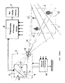
- FIGURE is a block diagram of an embodiment of means for implementing the method of the invention, and also serves to explain the method.
- the present invention relates to a method of detecting an incident on a portion of route 1 situated in a scene 2 when said portion of route is suitable for having objects of any kind traveling therealong, in particular when it is a portion of road suitable for having motor vehicles traveling therealong.
- the method is applied when a video camera 3 is used for implementing the method, the camera having a target 4 constituting an optoelectronic converter for converting a real optical image 5 of the scene 2 , and when said camera is associated with means 14 for varying at will the field of the objective lens 15 of the camera when it is constituted by a zoom lens, and/or for changing the pointing direction of the optical axis 16 of the camera so that the direction of said optical axis can be controlled in elevation and in azimuth.
- These means 14 are themselves well known and are therefore not described in greater detail herein in order to simplify the present description.
- scene is used to cover all of the elements of the scene in the field of view of the camera, and not only the portion of route.
- the target is analyzed by a programmable processor member 6 such as a microprocessor or the like, optionally associated with a non-volatile memory 17 such as a video recorder or the like, with incidents on the portion of route 1 in the scene 2 being detectable on activating the programmable processor member 6 only when the real image 5 of the scene as focused on the target 4 is stationary.
- a programmable processor member 6 such as a microprocessor or the like
- a non-volatile memory 17 such as a video recorder or the like
- the method of the invention thus consists in detecting the beginning of any displacement of the real image 5 of the scene 2 relative to the target 4 , in deactivating the programmable processor member 6 as soon as the real image 5 of the scene begins to move relative to the target, then in detecting the end of the displacement of the real image of the scene relative to the target, and finally in reactivating the programmable processor member at the end of the displacement of the real image 5 of the scene relative to the target 4 in order to implement the incident detection process on the portion of route 1 .
- the beginning and the end of displacement of the real image of the scene relative to the target are detected by determining at least a first image point 10 , 11 , 12 , . . . in said real image 5 of the scene 2 that corresponds to a fixed point 10 ′, 11 ′, 12 ′, . . . in the scene, and in generating a first command signal when said first image point is subject to a change of position on the target 4 , and then in controlling the programmable process member 6 as a function of said first command signal, i.e. initially deactivating the programmable processor member as soon as the real image starts to move, and subsequently reactivating the same programmable processor member at the end of the displacement of the real image so as to perform the iterative detection process using the technique that is itself known.
- the beginning and the end of the displacement of the real image 5 of the scene 2 relative to the target are detected by determining at least second and third image points 10 , 11 , 12 , . . . of the real image 5 of the scene 2 corresponding respectively to two stationary points 10 ′, 11 ′, 12 ′, . . . of said scene, in generating a second command signal when the distance between said second and third image points is subjected to a variation, and subsequently controlling the programmable processor member 6 as a function of the second command signal, i.e. initially deactivating the programmable processor member as soon as the real image begins to move, and then reactivating the same programmable processor member at the end of movement of the real image in order to perform the incident detection process using the technique that is itself known.
- the beginning and the end of movement of the real image of the scene relative to the target are detected initially by determining at least fourth and fifth image points 10 , 11 , 12 , . . . of the real image 5 of the scene 2 corresponding respectively to two stationary points 10 ′, 11 ′, 12 ′, . . . of the scene, in generating a third command signal when the distance between the fourth and fifth image points is subjected to a change, or when at least one of the fourth and fifth image points is subjected to a change of position on the target 4 , and in controlling the programmable processor member 6 as a function of the third command signal, i.e. initially deactivating the programmable processor member as soon as the real image begins to move, and subsequently reactivating the same programmable processor member at the end of the movement of the real image so as to perform the incident detection process using the technique that is itself known.
- the above-defined command signals pass, for example, from a first state to a second state when the beginning of movement of the real image 5 is detected, and from the second state back to the first state when the end of movement of said real image is detected.
- the programmable processor member 6 is deactivated throughout the period during which the command signal is in its second state.
- the stationary points 10 ′, 11 ′, 12 ′, . . . in the scene 2 may be constituted, for example, by points that are dark (or particularly bright) on roadside signaling panels, lamp posts, or the like, portions of advertising panels, or even points that are particularly dark (or particularly bright) in given vegetation.
- Detecting the beginning and the end either of movement of an image point of the real image 5 of the scene 2 relative to the target, or of variation in the distance between two image points, can easily be implemented, e.g. by means of the processor member 6 under the control of a suitable computer program adapted to implement the method of the invention, where writing such a program comes within the competence of the person skilled in the art who knows the above-explained method.
- the target 4 is made up of a plurality of photosensitive points, these photosensitive points being suitable for delivering signals that are a function of the quantity of radiation received on their photosensitive surfaces.
- the received surfaces of the photosensitive points are advantageously of substantially the same dimensions.
- commercially available video cameras generally include such targets.
- an incident can be detected on the portion of route 1 by activating the programmable processor member 6 only while the real image 5 of the scene 2 that is focused on the target 4 is stationary.
- the programmable processor member 6 When the programmable processor member 6 is activated, it is suitable for detecting incidents on the portion of route using various processes.
- This process for detecting an incident may also consist in subdividing the selected group of photosensitive points into a plurality of subgroups of photosensitive points corresponding to points on the portion of route situated at the intersections between the main construction lines and respective secondary geometrical construction lines extending substantially perpendicularly to the main construction lines, and in associating each photosensitive point of a subgroup with a weighting coefficient for multiplying the value of the signal emitted by said points, the weighting coefficients being a function of the preferential probability of objects passing on the point on the portion of route whose image is the photosensitive point associated with the weighting coefficient.
- the above-mentioned analysis of the signals delivered by the photosensitive points can consist in averaging the values of the signals delivered at given instants by the points in each subgroup, and then for each subgroup in comparing the averages obtained in this way and in deducing from the comparison whether an incident, if any, is present on the portion of route.
- the processor member 6 When the image becomes stable again, i.e. when the image point is analyzed as being stationary relative to the target, the processor member 6 again runs the process for detecting incidents using the AID type method as defined above.
- the processor member 6 again runs the process for detecting incidents using the AID method as defined above.
- the above-described method is described using one image point for determining whether the camera is moving in elevation and/or azimuth, and two image points for detecting whether it is zooming in or zooming out.
- the method can be implemented without manual intervention on the part of technicians every time there is a change in the pointing direction of the optical axis of the camera in elevation and/or azimuth, and/or every time there is a change in the field angle of its objective lens, while making use of the same devices as are used for implementing prior art methods, and without it being necessary to add additional hardware means thereto.
Landscapes
- General Physics & Mathematics (AREA)
- Physics & Mathematics (AREA)
- Engineering & Computer Science (AREA)
- Business, Economics & Management (AREA)
- Theoretical Computer Science (AREA)
- General Health & Medical Sciences (AREA)
- Health & Medical Sciences (AREA)
- Economics (AREA)
- Multimedia (AREA)
- Human Resources & Organizations (AREA)
- Marketing (AREA)
- Primary Health Care (AREA)
- Strategic Management (AREA)
- Tourism & Hospitality (AREA)
- General Business, Economics & Management (AREA)
- Traffic Control Systems (AREA)
- Closed-Circuit Television Systems (AREA)
- Image Processing (AREA)
Applications Claiming Priority (4)
| Application Number | Priority Date | Filing Date | Title |
|---|---|---|---|
| FR0209251 | 2002-07-22 | ||
| FR02/09251 | 2002-07-22 | ||
| FR0209251A FR2842637B1 (fr) | 2002-07-22 | 2002-07-22 | Procede pour detecter un incident ou analogue sur une portion de voie |
| PCT/FR2003/002188 WO2004012168A2 (fr) | 2002-07-22 | 2003-07-11 | Procede de detection d’incident sur route |
Publications (2)
| Publication Number | Publication Date |
|---|---|
| US20050213791A1 US20050213791A1 (en) | 2005-09-29 |
| US8055015B2 true US8055015B2 (en) | 2011-11-08 |
Family
ID=29797615
Family Applications (1)
| Application Number | Title | Priority Date | Filing Date |
|---|---|---|---|
| US10/521,606 Expired - Fee Related US8055015B2 (en) | 2002-07-22 | 2003-07-11 | Method of detecting an incident or the like on a portion of a route |
Country Status (6)
| Country | Link |
|---|---|
| US (1) | US8055015B2 (de) |
| EP (1) | EP1584079B1 (de) |
| KR (1) | KR101025383B1 (de) |
| AU (1) | AU2003273432A1 (de) |
| FR (1) | FR2842637B1 (de) |
| WO (1) | WO2004012168A2 (de) |
Cited By (3)
| Publication number | Priority date | Publication date | Assignee | Title |
|---|---|---|---|---|
| US20140208170A1 (en) * | 2003-10-01 | 2014-07-24 | Testplant, Inc. | Method for monitoring a graphical user interface on a second computer display from a first computer |
| US9240123B2 (en) | 2013-12-13 | 2016-01-19 | Here Global B.V. | Systems and methods for detecting road congestion and incidents in real time |
| US11507494B2 (en) | 2016-02-10 | 2022-11-22 | Eggplant Limited | Method of, and apparatus for, testing computer hardware and software |
Families Citing this family (1)
| Publication number | Priority date | Publication date | Assignee | Title |
|---|---|---|---|---|
| FR2930668B1 (fr) * | 2008-04-25 | 2010-06-18 | Citilog | Systeme d'aide a l'exploitation d'un reseau routier a qualite de service |
Citations (12)
| Publication number | Priority date | Publication date | Assignee | Title |
|---|---|---|---|---|
| US4847772A (en) | 1987-02-17 | 1989-07-11 | Regents Of The University Of Minnesota | Vehicle detection through image processing for traffic surveillance and control |
| US5296852A (en) * | 1991-02-27 | 1994-03-22 | Rathi Rajendra P | Method and apparatus for monitoring traffic flow |
| US5396283A (en) * | 1991-03-19 | 1995-03-07 | Mitsubishi Denki Kabushiki Kaisha | Moving body measuring device and an image processing device for measuring traffic flows |
| US5422673A (en) * | 1992-06-10 | 1995-06-06 | Sony Corporation | Video camera with automatic focus control |
| US5774569A (en) * | 1994-07-25 | 1998-06-30 | Waldenmaier; H. Eugene W. | Surveillance system |
| US5798793A (en) * | 1992-07-10 | 1998-08-25 | Canon Kabushiki Kaisha | Automatic focusing device capable of detecting panning |
| US5912634A (en) * | 1994-04-08 | 1999-06-15 | Traficon N.V. | Traffic monitoring device and method |
| US6137531A (en) * | 1997-04-15 | 2000-10-24 | Fujitsu Limited | Detecting device for road monitoring |
| US6177885B1 (en) * | 1998-11-03 | 2001-01-23 | Esco Electronics, Inc. | System and method for detecting traffic anomalies |
| US6188778B1 (en) * | 1997-01-09 | 2001-02-13 | Sumitomo Electric Industries, Ltd. | Traffic congestion measuring method and apparatus and image processing method and apparatus |
| WO2001033503A1 (en) * | 1999-11-03 | 2001-05-10 | Cet Technologies Pte Ltd | Image processing techniques for a video based traffic monitoring system and methods therefor |
| US6470261B1 (en) * | 1998-07-31 | 2002-10-22 | Cet Technologies Pte Ltd | Automatic freeway incident detection system and method using artificial neural network and genetic algorithms |
Family Cites Families (6)
| Publication number | Priority date | Publication date | Assignee | Title |
|---|---|---|---|---|
| KR960706644A (ko) * | 1993-12-08 | 1996-12-09 | 테릴 켄트 퀄리 | 단안시 시스템용 배경 결정 및 제거를 위한 방법 및 장치(method and apparatus for background determination and subtraction for a monocular vision system) |
| MY132441A (en) * | 1995-01-17 | 2007-10-31 | Sarnoff Corp | Method and apparatus for detecting object movement within an image sequence |
| US6727938B1 (en) * | 1997-04-14 | 2004-04-27 | Robert Bosch Gmbh | Security system with maskable motion detection and camera with an adjustable field of view |
| US6760061B1 (en) * | 1997-04-14 | 2004-07-06 | Nestor Traffic Systems, Inc. | Traffic sensor |
| JP3567066B2 (ja) * | 1997-10-31 | 2004-09-15 | 株式会社日立製作所 | 移動体組合せ検出装置および方法 |
| FR2785432B1 (fr) * | 1998-10-30 | 2001-01-19 | Citilog | Procede permettant d'analyser l'etat d'une portion de voie et de son environnement |
-
2002
- 2002-07-22 FR FR0209251A patent/FR2842637B1/fr not_active Expired - Fee Related
-
2003
- 2003-07-11 AU AU2003273432A patent/AU2003273432A1/en not_active Abandoned
- 2003-07-11 KR KR1020057000408A patent/KR101025383B1/ko not_active Expired - Fee Related
- 2003-07-11 US US10/521,606 patent/US8055015B2/en not_active Expired - Fee Related
- 2003-07-11 WO PCT/FR2003/002188 patent/WO2004012168A2/fr not_active Ceased
- 2003-07-11 EP EP03755590.1A patent/EP1584079B1/de not_active Expired - Lifetime
Patent Citations (12)
| Publication number | Priority date | Publication date | Assignee | Title |
|---|---|---|---|---|
| US4847772A (en) | 1987-02-17 | 1989-07-11 | Regents Of The University Of Minnesota | Vehicle detection through image processing for traffic surveillance and control |
| US5296852A (en) * | 1991-02-27 | 1994-03-22 | Rathi Rajendra P | Method and apparatus for monitoring traffic flow |
| US5396283A (en) * | 1991-03-19 | 1995-03-07 | Mitsubishi Denki Kabushiki Kaisha | Moving body measuring device and an image processing device for measuring traffic flows |
| US5422673A (en) * | 1992-06-10 | 1995-06-06 | Sony Corporation | Video camera with automatic focus control |
| US5798793A (en) * | 1992-07-10 | 1998-08-25 | Canon Kabushiki Kaisha | Automatic focusing device capable of detecting panning |
| US5912634A (en) * | 1994-04-08 | 1999-06-15 | Traficon N.V. | Traffic monitoring device and method |
| US5774569A (en) * | 1994-07-25 | 1998-06-30 | Waldenmaier; H. Eugene W. | Surveillance system |
| US6188778B1 (en) * | 1997-01-09 | 2001-02-13 | Sumitomo Electric Industries, Ltd. | Traffic congestion measuring method and apparatus and image processing method and apparatus |
| US6137531A (en) * | 1997-04-15 | 2000-10-24 | Fujitsu Limited | Detecting device for road monitoring |
| US6470261B1 (en) * | 1998-07-31 | 2002-10-22 | Cet Technologies Pte Ltd | Automatic freeway incident detection system and method using artificial neural network and genetic algorithms |
| US6177885B1 (en) * | 1998-11-03 | 2001-01-23 | Esco Electronics, Inc. | System and method for detecting traffic anomalies |
| WO2001033503A1 (en) * | 1999-11-03 | 2001-05-10 | Cet Technologies Pte Ltd | Image processing techniques for a video based traffic monitoring system and methods therefor |
Non-Patent Citations (3)
| Title |
|---|
| Kamijo et al, "Traffic Monitoring and Accident Detection at Intersections", IEEE Transactions on Intelligent Transportation Systems, vol. 1, No. 2, Jun. 2000. * |
| Kun-feng Wang; Xingwu Jia; Shuming Tang, "A survey of vision-based automatic incident detection technology," Vehicular Electronics and Safety, 2005. IEEE International Conference on , vol., No., pp. 290-295, Oct. 14-16, 2005. * |
| Shuming et al, "Traffic Incident Detection Algorithm Based on Non-parameter Regression", Intelligent Transportation Systems, 2002. Proceedings. The IEEE 5th International Conference on Publication Date: 2002, on pp. 714-719. * |
Cited By (5)
| Publication number | Priority date | Publication date | Assignee | Title |
|---|---|---|---|---|
| US20140208170A1 (en) * | 2003-10-01 | 2014-07-24 | Testplant, Inc. | Method for monitoring a graphical user interface on a second computer display from a first computer |
| US9477567B2 (en) * | 2003-10-01 | 2016-10-25 | Testplant, Inc. | Method for monitoring a graphical user interface on a second computer display from a first computer |
| US9658931B2 (en) | 2003-10-01 | 2017-05-23 | TestPlant Inc. | Method for monitoring a graphical user interface on a second computer display from a first computer |
| US9240123B2 (en) | 2013-12-13 | 2016-01-19 | Here Global B.V. | Systems and methods for detecting road congestion and incidents in real time |
| US11507494B2 (en) | 2016-02-10 | 2022-11-22 | Eggplant Limited | Method of, and apparatus for, testing computer hardware and software |
Also Published As
| Publication number | Publication date |
|---|---|
| AU2003273432A1 (en) | 2004-02-16 |
| WO2004012168A2 (fr) | 2004-02-05 |
| EP1584079B1 (de) | 2019-04-03 |
| US20050213791A1 (en) | 2005-09-29 |
| FR2842637A1 (fr) | 2004-01-23 |
| EP1584079A2 (de) | 2005-10-12 |
| KR20050023402A (ko) | 2005-03-09 |
| KR101025383B1 (ko) | 2011-03-28 |
| FR2842637B1 (fr) | 2004-10-01 |
| WO2004012168A3 (fr) | 2004-04-08 |
Similar Documents
| Publication | Publication Date | Title |
|---|---|---|
| RU2763800C1 (ru) | Бортовая сенсорная система | |
| US12146961B2 (en) | Vehicle behavior detection device and detection system | |
| US20100305858A1 (en) | Non-kinematic behavioral mapping | |
| EP3239738B1 (de) | Priorisierte sensordatenverarbeitung mit karteninformationen für automatische fahrzeuge | |
| CN107360394B (zh) | 应用于边防视频监控系统的多预置点动态智能监测方法 | |
| US11914041B2 (en) | Detection device and detection system | |
| JP2019526056A (ja) | 車両の形状に適応したダイナミックステアドlidar | |
| US11914367B2 (en) | Sun-aware routing and controls of an autonomous vehicle | |
| EP0680026B1 (de) | Überwachungsanlage im Strassenverkehr | |
| JP7238853B2 (ja) | 地図生成用データ収集装置及び地図生成用データ収集方法 | |
| CN114274978B (zh) | 一种无人驾驶物流车的避障方法 | |
| KR20230020184A (ko) | 고정 카메라 및 이동 카메라를 이용한 영상 분석 장치 | |
| US8055015B2 (en) | Method of detecting an incident or the like on a portion of a route | |
| US12468041B2 (en) | System, method, and components providing compressive active range sampling | |
| CN111216734A (zh) | 相机盲区中对象检测的方法及装置 | |
| KR102317311B1 (ko) | 영상을 이용한 정보 분석 시스템 및 그에 관한 방법 | |
| CN114616155B (zh) | 用于运行车辆的至少一个环境检测传感器的方法 | |
| JP2004199649A (ja) | 突発事象検出方法 | |
| JP2024021706A (ja) | 監視装置および監視方法 | |
| Majumder | An Approach to Counting Vehicles from Pre-Recorded Video Using Computer Algorithms | |
| CN110874924A (zh) | 智能路侧单元及其调控方法 | |
| CN119380557B (zh) | 基于物联网的公路感知一体化系统 | |
| CN114089299A (zh) | 一种基于态势感知多源传感器联动的海上目标检测识别方法 | |
| Vermeulen | Automatic Incident Detection (AID) with thermal cameras | |
| Everson et al. | Sensor performance and weather effects modeling for Intelligent Transportation Systems (ITS) applications |
Legal Events
| Date | Code | Title | Description |
|---|---|---|---|
| AS | Assignment |
Owner name: CITILOG, FRANCE Free format text: ASSIGNMENT OF ASSIGNORS INTEREST;ASSIGNOR:BOUZAR, SALAH;REEL/FRAME:016694/0730 Effective date: 20041209 |
|
| ZAAA | Notice of allowance and fees due |
Free format text: ORIGINAL CODE: NOA |
|
| ZAAB | Notice of allowance mailed |
Free format text: ORIGINAL CODE: MN/=. |
|
| STCF | Information on status: patent grant |
Free format text: PATENTED CASE |
|
| FPAY | Fee payment |
Year of fee payment: 4 |
|
| FEPP | Fee payment procedure |
Free format text: PAT HOLDER NO LONGER CLAIMS SMALL ENTITY STATUS, ENTITY STATUS SET TO UNDISCOUNTED (ORIGINAL EVENT CODE: STOL); ENTITY STATUS OF PATENT OWNER: LARGE ENTITY |
|
| MAFP | Maintenance fee payment |
Free format text: PAYMENT OF MAINTENANCE FEE, 8TH YEAR, LARGE ENTITY (ORIGINAL EVENT CODE: M1552); ENTITY STATUS OF PATENT OWNER: LARGE ENTITY Year of fee payment: 8 |
|
| FEPP | Fee payment procedure |
Free format text: MAINTENANCE FEE REMINDER MAILED (ORIGINAL EVENT CODE: REM.); ENTITY STATUS OF PATENT OWNER: LARGE ENTITY |
|
| LAPS | Lapse for failure to pay maintenance fees |
Free format text: PATENT EXPIRED FOR FAILURE TO PAY MAINTENANCE FEES (ORIGINAL EVENT CODE: EXP.); ENTITY STATUS OF PATENT OWNER: LARGE ENTITY |
|
| STCH | Information on status: patent discontinuation |
Free format text: PATENT EXPIRED DUE TO NONPAYMENT OF MAINTENANCE FEES UNDER 37 CFR 1.362 |
|
| FP | Lapsed due to failure to pay maintenance fee |
Effective date: 20231108 |