US8044656B2 - Device for calibration of a field transmitter - Google Patents
Device for calibration of a field transmitter Download PDFInfo
- Publication number
- US8044656B2 US8044656B2 US12/296,372 US29637207A US8044656B2 US 8044656 B2 US8044656 B2 US 8044656B2 US 29637207 A US29637207 A US 29637207A US 8044656 B2 US8044656 B2 US 8044656B2
- Authority
- US
- United States
- Prior art keywords
- component
- transmitter
- calibration
- magnetic fields
- sensing magnetic
- Prior art date
- Legal status (The legal status is an assumption and is not a legal conclusion. Google has not performed a legal analysis and makes no representation as to the accuracy of the status listed.)
- Expired - Fee Related, expires
Links
- 230000005291 magnetic effect Effects 0.000 claims abstract description 62
- 230000004913 activation Effects 0.000 claims abstract description 17
- 238000005259 measurement Methods 0.000 claims abstract description 13
- 230000003213 activating effect Effects 0.000 claims description 11
- 239000007787 solid Substances 0.000 claims description 4
- 230000001681 protective effect Effects 0.000 claims description 2
- 238000000034 method Methods 0.000 description 7
- 230000008569 process Effects 0.000 description 5
- 238000012545 processing Methods 0.000 description 5
- BGPVFRJUHWVFKM-UHFFFAOYSA-N N1=C2C=CC=CC2=[N+]([O-])C1(CC1)CCC21N=C1C=CC=CC1=[N+]2[O-] Chemical compound N1=C2C=CC=CC2=[N+]([O-])C1(CC1)CCC21N=C1C=CC=CC1=[N+]2[O-] BGPVFRJUHWVFKM-UHFFFAOYSA-N 0.000 description 4
- 239000012530 fluid Substances 0.000 description 4
- 238000009434 installation Methods 0.000 description 4
- 238000010586 diagram Methods 0.000 description 3
- 230000007935 neutral effect Effects 0.000 description 3
- 238000004891 communication Methods 0.000 description 2
- 238000004880 explosion Methods 0.000 description 2
- 239000007789 gas Substances 0.000 description 2
- 230000003993 interaction Effects 0.000 description 2
- 238000004519 manufacturing process Methods 0.000 description 2
- 235000014676 Phragmites communis Nutrition 0.000 description 1
- 238000009530 blood pressure measurement Methods 0.000 description 1
- 239000003990 capacitor Substances 0.000 description 1
- 238000010276 construction Methods 0.000 description 1
- 230000007613 environmental effect Effects 0.000 description 1
- 239000002360 explosive Substances 0.000 description 1
- 239000003302 ferromagnetic material Substances 0.000 description 1
- 231100001261 hazardous Toxicity 0.000 description 1
- 238000010438 heat treatment Methods 0.000 description 1
- 239000000463 material Substances 0.000 description 1
- 238000012986 modification Methods 0.000 description 1
- 230000004048 modification Effects 0.000 description 1
- 238000003825 pressing Methods 0.000 description 1
- 238000000926 separation method Methods 0.000 description 1
- 238000007493 shaping process Methods 0.000 description 1
- 230000007480 spreading Effects 0.000 description 1
- 238000003892 spreading Methods 0.000 description 1
- 230000001131 transforming effect Effects 0.000 description 1
Images


Classifications
-
- H—ELECTRICITY
- H01—ELECTRIC ELEMENTS
- H01H—ELECTRIC SWITCHES; RELAYS; SELECTORS; EMERGENCY PROTECTIVE DEVICES
- H01H36/00—Switches actuated by change of magnetic field or of electric field, e.g. by change of relative position of magnet and switch, by shielding
- H01H36/0006—Permanent magnet actuating reed switches
- H01H36/0033—Mountings; Housings; Connections
-
- H—ELECTRICITY
- H05—ELECTRIC TECHNIQUES NOT OTHERWISE PROVIDED FOR
- H05K—PRINTED CIRCUITS; CASINGS OR CONSTRUCTIONAL DETAILS OF ELECTRIC APPARATUS; MANUFACTURE OF ASSEMBLAGES OF ELECTRICAL COMPONENTS
- H05K7/00—Constructional details common to different types of electric apparatus
- H05K7/14—Mounting supporting structure in casing or on frame or rack
- H05K7/1462—Mounting supporting structure in casing or on frame or rack for programmable logic controllers [PLC] for automation or industrial process control
-
- H—ELECTRICITY
- H01—ELECTRIC ELEMENTS
- H01H—ELECTRIC SWITCHES; RELAYS; SELECTORS; EMERGENCY PROTECTIVE DEVICES
- H01H36/00—Switches actuated by change of magnetic field or of electric field, e.g. by change of relative position of magnet and switch, by shielding
- H01H36/0006—Permanent magnet actuating reed switches
- H01H36/006—Permanent magnet actuating reed switches comprising a plurality of reed switches, e.g. selectors or joystick-operated
Definitions
- the present invention relates to a device for calibration of a field transmitter having improved structure and characteristics.
- This application is a 371 of PCT/EP07/52592 filed on Mar. 19, 2007.
- these field transmitters comprise a suitably configured enclosure, inside which there are housed the various components for sensing, typically including: a pressure sensor to obtain easily from one or more relative, differential or absolute pressure measurements, measurement values also relating to other physical variables of the controlled process fluid which would be more difficult to transduce directly; appropriate primary electronic circuits for processing signals coming from the pressure sensor; secondary electronic circuits for processing signals coming from the primary electronic circuits and then delegated with managing communication with other transmitters or with control units; displays for on-site viewing of the sensed variables, terminal blocks for the various connections; and electrical power supply circuits of the components, etc.
- a pressure sensor to obtain easily from one or more relative, differential or absolute pressure measurements, measurement values also relating to other physical variables of the controlled process fluid which would be more difficult to transduce directly
- appropriate primary electronic circuits for processing signals coming from the pressure sensor
- secondary electronic circuits for processing signals coming from the primary electronic circuits and then delegated with managing communication with other transmitters or with control units
- displays for on-site viewing of the sensed variables, terminal blocks
- these transmitters are generally provided with specific devices to perform calibration operations which during installation allow setting of a minimum value, generally zero, and a maximum value, typically the span/full scale value which define the ends of the measurement range of said transmitter.
- the covering plate must first be removed, and then the screws inserted in the blind holes must be loosened; this allows extension of the spring and relative movement of the permanent magnet, which in this way magnetically actuates the corresponding magnetic switch inside the enclosure.
- the electronics associated with the two magnetic switches consequently adjust the two minimum and maximum, or zero/span values, of the transmitter.
- the operator must reposition all the components.
- the principal aim of the present invention is to produce a device for calibration of a field transmitter, which allows the previously cited drawbacks to be overcome, and in particular, which with respect to known devices has an optimized constructive structure, both as regards installation and simplified use, and offers suitable characteristics of reliability and safety in use.
- a device for calibration of a field transmitter characterized in that it comprises a shaped body on which there are disposed first means for sensing magnetic fields the activation of which allows calibration of a first measurement parameter of the transmitter, second means for sensing magnetic fields the activation of which allows calibration of a second measurement parameter of the transmitter, magnetic actuation means suitable to activate said first and second means for sensing magnetic fields, said shaped body being configured so that it can be removably connected to the transmitter on the external surface of the enclosure thereof.
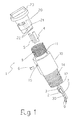
- FIG. 1 is a perspective exploded view illustrating a possible embodiment of the device according to the invention
- FIG. 2 is a sectional view schematically illustrating the device in FIG. 1 in a non-activating position
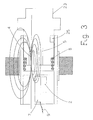
- FIG. 3 is the section of FIG. 2 rotated through 90° illustrating the trend of the magnetic field in a non-activating position
- FIGS. 4 and 5 are sectional views schematically illustrating the device according to the invention in the activating position respectively of the first and of the second means for sensing magnetic fields;
- FIG. 6 is a block diagram of an electronic processing circuit used in the device according to the invention.
- FIG. 7 is a perspective view of a field transmitter using a calibration device according to the invention.
- FIG. 8 is a circuit diagram illustrating a possible embodiment of the electronic circuit in FIG. 6 .
- FIG. 1 is an exploded view of a possible embodiment of a device according to the invention for calibration of a field transmitter; these transmitters are industrial devices suitable to sense/measure a physical variable of a process fluid, i.e. pressure.
- An example of a field transmitter, in particular a pressure transmitter is represented in FIG. 7 with the reference number 100 , which, according to widely known embodiments and for this reason not illustrated in detail, comprises an enclosure 101 housed inside which there are various components, generally including a sensor, such as a pressure sensor, electronic processing means that are operatively associated with the sensor and process the signals sensed thereby, a terminal block for the various internal and external connections to the transmitter, etc.
- a sensor such as a pressure sensor
- electronic processing means that are operatively associated with the sensor and process the signals sensed thereby
- a terminal block for the various internal and external connections to the transmitter, etc.
- the device for calibration of a field transmitter 100 of the type mentioned above comprises a shaped body 1 configured so that it can be removably connected to the transmitter 100 on the external surface of the enclosure 101 , according to the methods to be described below; in particular, directly on the shaped body 1 there are disposed first means for sensing magnetic fields 2 the activation of which allows calibration of a first measurement parameter of the transmitter, such as the zero of the transmitter, and second means for sensing magnetic fields 3 the activation of which allows calibration of a second measurement parameter of the transmitter, such as the span/full scale value. Also disposed on the body 1 are magnetic actuating means suitable to activate the first 2 and/or second 3 means for sensing magnetic fields, as will be apparent from the description below.
- FIGS. 6 and 8 respectively show a block diagram and a possible embodiment (R 1 , R 2 , etc. indicate resistors, C indicates capacitors, D indicates diodes, and so forth); said circuit 30 is operatively connected to the first and second magnetic means 2 and 3 and is designed to be operatively connected, during installation, to the electronic processing means of the transmitter 100 .
- the shaped body 1 comprises two principal component parts of which: a first component 10 to which the first and the second means for sensing magnetic activation fields 2 and 3 are operatively connected, which is suitable to be removably connected to the enclosure 101 of the transmitter 100 ; and a second component 20 to which the magnetic actuation means are operatively connected, which is connected to the first component 10 movably in relation thereto; preferably, the second component 20 is coupled to the first component 10 rotatably in relation thereto.
- the two components 10 and 20 are coupled relatively movably to each other so that, in operating conditions, the magnetic actuation means are positionable in a neutral non-activating position of the first and of the second magnetic means 2 and 3 , or in activating position/positions thereof; in particular, the magnetic actuation means are housed on the body of the second component 20 and are configured to take, following movement of the second component 20 with respect to the first component 10 , besides the neutral non-activating position, a first position for activating only the first means for sensing magnetic fields 2 , or alternatively, a second position for activating the second means for sensing magnetic fields 3 .
- the first component 10 comprises a first hollow portion 11 suitable to at least partially house the second component 20 , and a second portion 12 , also hollow, in which the first and the second means for sensing magnetic fields 2 and 3 , and the electronic circuit 30 associated therewith, are housed; the two hollow portions 11 and 12 extend on opposite sides to each other with respect to a solid dividing wall 13 which forms the bottom wall of both hollow portions.
- the second hollow portion 12 is threaded on at least part of the external surface 14 thereof, to allow screwing into a corresponding seat 102 provided on the outside of the enclosure 101 of the transmitter 100 .
- the second component 20 comprises a substantially solid body in the shape of a push button having a lower portion 21 , i.e. substantially cylindrical in shape, suitable to be inserted inside the first hollow portion 11 , and in which there is produced at least one seat 22 to house the magnetic actuating means, and an upper or top portion 23 which projects from the first hollow portion 11 to be actuated by an operator.
- the magnetic actuation means preferably comprise an activation magnet 4 and a protective shield 5 , produced, for example, with a plate made of ferromagnetic material, which are housed in two respective seats 22 produced in the lower portion 21 of the second component 20 , for example, by forcing them into said seats 22 so that they are substantially integral with said second component 20 .
- the first and second means for sensing magnetic fields comprise, respectively, a first magnetic switch 2 and a second magnetic switch 3 , constituted, for example, by reed relays, which are positioned on a supporting element or board 7 , on which an electronic circuit 30 operatively connected thereto is also disposed; this supporting element 7 , with the components disposed thereon, is housed in the second hollow portion 12 with the ends inserted in corresponding grooves produced in the inner walls of said second portion 12 .
- the two components 10 and 20 are mechanically coupled to each other through means for operatively connecting and guiding the second component 20 in relation to the first component 10 ; in particular, these connecting and guiding means comprise a stopper pin 6 which, as illustrated in FIG. 2 , passes through a through hole 15 disposed in the wall of the first hollow portion 11 , and is inserted in a branched channel or race 25 produced in the lower portion 21 of the second component 20 .
- the means for operatively connecting and guiding comprise an elastic element 8 , such as a spring, which is disposed housed inside the first hollow portion 11 so as to encircle the lower portion 21 and act in contrast with the upper portion 23 of the second component 20 .
- an elastic element 8 such as a spring
- the device with the various elements assembled is operatively connected to a transmitter by operatively connecting the electronic circuit 30 to the electronics of said transmitter; in particular, this operation can be performed simply by connecting two wires, indicated schematically in the figures by the reference number 9 , to the terminal block 35 of the transmitter which in turn is connected to the electronics 36 of said transmitter.
- the device is then connected mechanically by screwing the first component 10 into the threaded seat 102 so that the device takes the position illustrated schematically in FIG. 2 .
- the pin 6 is inserted in the vertical section of the race 25 and the spring 8 holds the second component 20 at a suitable distance to prevent accidental activation of the two magnetic switches 2 and 3 .
- the trend of the magnetic field resulting from interaction between magnet 4 and shield 5 is such that neither of the two magnetic switches 2 and 3 is activated, as illustrated schematically in FIG. 3 .
- each magnetic switch 2 or 3 which in practice causes them to switch from an OFF state to an ON state, allows passage of a corresponding input signal towards the electronic circuit 30 ; this signal is suitably processed through: a microprocessor 31 , i.e. a model PIC 10F206 microcontroller, which receives the input signal and emits a corresponding signal, i.e. in the form of a square wave type signal; a signal generator 32 , i.e.
- a band pass filter which filters the output signal from the microprocessor 31 transforming it into a sinusoidal type physical signal; and a circuit to adjust the power supply voltage 33 which is operatively connected to the terminals through the wires 9 and allows adjustment of the power supply voltage of said circuit 30 and protection against heating, overvoltages, etc.
- the electronics 30 communicate to the electronics 36 of the transmitter 100 that activation of one of the two functions has taken place, i.e. through a digital communication protocol, i.e. of the HART type; consequently, the electronics of the transmitter set first one and then the other of the parameters as a function of the signal received from one or other magnetic switch 2 , 3 .
- the two parameters are in practice calibrated in sequence; as stated, these parameters allow, for example, setting of the zero and span/full scale values of the transmitter, thereby defining the ends of the measurement/sensing range.
- the calibration device allows the aim and the objects set to be fully achieved, providing a series of advantages with respect to prior art.
- the device is produced according to a constructive structure optimized both as a whole and in the single elements, easy to install and use, and functionally efficient.
- the device has a functionally stand-alone structure, on which all the basic elements required for calibration operations are positioned directly, and which is coupled to the transmitter on the outside thereof as a sort of separate accessory, replaceable or removable at any time.
- This stand-alone functionality also allows it to be used with transmitters that are not have electromagnetic components inside for calibration operations.
- the entire assembly is produced in full compliance with the requirements of reliability and safety; in fact, thanks in particular to the configuration of the two components 10 and 20 , there is in practice a clean separation between the external atmosphere and the internal part of the transmitter as the only interaction is the initial one to connect the connection wires 9 , and calibration operations take place exclusively from the outside of the transmitter body; any flames or sparks that are generated inside cannot spread to the outside as the thread on the external surface 14 forms a sufficiently long and safe flame path.
- a further object of the present invention is a transmitter, in particular a pressure transmitter, characterized in that it comprises a calibration device as previously described.
- the device thus conceived is susceptible to numerous modifications and variants, all falling within the scope of the inventive concept; for example, the shaped body 1 could be produced with a different number of components, the shaping of the components 10 and 20 could be modified, as could the reciprocal positioning of the various elements, provided that this is compatible with the functionalities for which they have been designed and configured.
Landscapes
- Engineering & Computer Science (AREA)
- Automation & Control Theory (AREA)
- Microelectronics & Electronic Packaging (AREA)
- Measuring Fluid Pressure (AREA)
- Geophysics And Detection Of Objects (AREA)
- Arrangements For Transmission Of Measured Signals (AREA)
- Testing Or Calibration Of Command Recording Devices (AREA)
Applications Claiming Priority (4)
| Application Number | Priority Date | Filing Date | Title |
|---|---|---|---|
| IT000716A ITMI20060716A1 (it) | 2006-04-11 | 2006-04-11 | Dispositivo per la taratura di un trasmettitore di campo |
| ITMI2006A000716 | 2006-04-11 | ||
| ITMI2006A0716 | 2006-04-11 | ||
| PCT/EP2007/052592 WO2007115905A2 (en) | 2006-04-11 | 2007-03-19 | Device for calibration of a field transmitter |
Publications (2)
| Publication Number | Publication Date |
|---|---|
| US20100156396A1 US20100156396A1 (en) | 2010-06-24 |
| US8044656B2 true US8044656B2 (en) | 2011-10-25 |
Family
ID=38508905
Family Applications (1)
| Application Number | Title | Priority Date | Filing Date |
|---|---|---|---|
| US12/296,372 Expired - Fee Related US8044656B2 (en) | 2006-04-11 | 2007-03-19 | Device for calibration of a field transmitter |
Country Status (6)
| Country | Link |
|---|---|
| US (1) | US8044656B2 (de) |
| EP (1) | EP2005457B1 (de) |
| CN (1) | CN101421808B (de) |
| ES (1) | ES2388304T3 (de) |
| IT (1) | ITMI20060716A1 (de) |
| WO (1) | WO2007115905A2 (de) |
Families Citing this family (4)
| Publication number | Priority date | Publication date | Assignee | Title |
|---|---|---|---|---|
| CN103278216A (zh) * | 2013-05-31 | 2013-09-04 | 江苏多维科技有限公司 | 液位传感器系统 |
| DE102015102947A1 (de) * | 2015-03-02 | 2016-09-08 | Endress + Hauser Gmbh + Co. Kg | Feldgerät der Automatisierungstechnik |
| DE102016004527B3 (de) * | 2016-04-13 | 2017-05-11 | Rosenberger Hochfrequenztechnik Gmbh & Co. Kg | Kalibrieranordnung und Verfahren zum Betrieb einer Kalibrieranordnung |
| CA3030409A1 (en) * | 2018-01-19 | 2019-07-19 | Ascension Technology Corporation | Calibrating a magnetic transmitter |
Citations (7)
| Publication number | Priority date | Publication date | Assignee | Title |
|---|---|---|---|---|
| GB1261393A (en) | 1969-03-28 | 1972-01-26 | Ass Eng Ltd | Inductive transducers |
| US4112272A (en) | 1976-11-24 | 1978-09-05 | Siemens Aktiengesellschaft | Valve and switch device for measuring pressure of liquids in living objects |
| US5167626A (en) * | 1990-10-02 | 1992-12-01 | Glaxo Inc. | Medical capsule device actuated by radio-frequency (RF) signal |
| US5278543A (en) | 1987-10-22 | 1994-01-11 | Rosemount Inc. | Transmitter with magnetic zero/span actuator |
| EP0597570A1 (de) | 1992-11-13 | 1994-05-18 | International Control Automation Finance S.A. | Magnetische Stellglieder |
| WO2004081501A1 (en) | 2003-03-11 | 2004-09-23 | Stevan Vukomanovic | Level indicator with magnetic switch |
| US20090258618A1 (en) * | 2006-04-11 | 2009-10-15 | Abb S.P.A | Accessory device for a field transmitter |
Family Cites Families (1)
| Publication number | Priority date | Publication date | Assignee | Title |
|---|---|---|---|---|
| US411272A (en) * | 1889-09-17 | George m |
-
2006
- 2006-04-11 IT IT000716A patent/ITMI20060716A1/it unknown
-
2007
- 2007-03-19 WO PCT/EP2007/052592 patent/WO2007115905A2/en not_active Ceased
- 2007-03-19 EP EP07727069A patent/EP2005457B1/de not_active Not-in-force
- 2007-03-19 ES ES07727069T patent/ES2388304T3/es active Active
- 2007-03-19 US US12/296,372 patent/US8044656B2/en not_active Expired - Fee Related
- 2007-03-19 CN CN2007800128198A patent/CN101421808B/zh not_active Expired - Fee Related
Patent Citations (7)
| Publication number | Priority date | Publication date | Assignee | Title |
|---|---|---|---|---|
| GB1261393A (en) | 1969-03-28 | 1972-01-26 | Ass Eng Ltd | Inductive transducers |
| US4112272A (en) | 1976-11-24 | 1978-09-05 | Siemens Aktiengesellschaft | Valve and switch device for measuring pressure of liquids in living objects |
| US5278543A (en) | 1987-10-22 | 1994-01-11 | Rosemount Inc. | Transmitter with magnetic zero/span actuator |
| US5167626A (en) * | 1990-10-02 | 1992-12-01 | Glaxo Inc. | Medical capsule device actuated by radio-frequency (RF) signal |
| EP0597570A1 (de) | 1992-11-13 | 1994-05-18 | International Control Automation Finance S.A. | Magnetische Stellglieder |
| WO2004081501A1 (en) | 2003-03-11 | 2004-09-23 | Stevan Vukomanovic | Level indicator with magnetic switch |
| US20090258618A1 (en) * | 2006-04-11 | 2009-10-15 | Abb S.P.A | Accessory device for a field transmitter |
Non-Patent Citations (3)
| Title |
|---|
| European Office Action in corresponding Application No. 07 727 069.2-1242 dated Feb. 25, 2009. |
| Form PCT/ISA/210 (International Search Report) dated Nov. 20, 2007. |
| Form PCT/ISA/237 (Written Opinion of the International Searching Authority) dated Nov. 20, 2007. |
Also Published As
| Publication number | Publication date |
|---|---|
| WO2007115905A2 (en) | 2007-10-18 |
| ITMI20060716A1 (it) | 2007-10-12 |
| EP2005457A2 (de) | 2008-12-24 |
| WO2007115905A3 (en) | 2008-01-10 |
| ES2388304T3 (es) | 2012-10-11 |
| EP2005457B1 (de) | 2012-06-06 |
| US20100156396A1 (en) | 2010-06-24 |
| CN101421808A (zh) | 2009-04-29 |
| CN101421808B (zh) | 2012-05-02 |
Similar Documents
| Publication | Publication Date | Title |
|---|---|---|
| US8044656B2 (en) | Device for calibration of a field transmitter | |
| US6522261B2 (en) | Selectable candela strobe unit | |
| US10295425B2 (en) | Temperature-compensated pressure gauge with a switch output | |
| US6981421B2 (en) | Pressure gage and switch | |
| KR20160038018A (ko) | 구성가능한 스위치 에뮬레이터 모듈 | |
| US4975687A (en) | Hall effect signalling gauge | |
| EP3175176B1 (de) | Flammenzündsteuerungsvorrichtung für brenner oder dergleichen | |
| US8290455B2 (en) | Accessory device for a field transmitter | |
| US20210066852A1 (en) | Protection device for a plug-in connection | |
| US20080247125A1 (en) | Handheld Housing for Wall-Mount Controller | |
| AU2010202652A1 (en) | Improvement in Switches | |
| JP2668571B2 (ja) | 磁気的ゼロ/スパンアクチュエータ付送信装置 | |
| US5278543A (en) | Transmitter with magnetic zero/span actuator | |
| JP2017103484A (ja) | 電気機器 | |
| US12609010B2 (en) | Smart conduit plug | |
| EP4189289B1 (de) | Gaszufuhrhahn mit positionssensor | |
| KR20170003450U (ko) | 조작부가 결합된 주방용 자동 가스차단기 | |
| KR200443917Y1 (ko) | 와이드 디스플레이 타입 가연성 가스 탐지기 | |
| JPH02254332A (ja) | 圧力スイッチ | |
| JP2014199892A (ja) | 電気機器 | |
| JP2017103485A (ja) | 電気機器 |
Legal Events
| Date | Code | Title | Description |
|---|---|---|---|
| AS | Assignment |
Owner name: ABB S.P.A.,ITALY Free format text: ASSIGNMENT OF ASSIGNORS INTEREST;ASSIGNORS:MORONI, ANDREA;DELL'ORO, ALESSANDRO;DOS SANTOS, RONALDO;SIGNING DATES FROM 20080929 TO 20080930;REEL/FRAME:021662/0126 Owner name: ABB S.P.A., ITALY Free format text: ASSIGNMENT OF ASSIGNORS INTEREST;ASSIGNORS:MORONI, ANDREA;DELL'ORO, ALESSANDRO;DOS SANTOS, RONALDO;SIGNING DATES FROM 20080929 TO 20080930;REEL/FRAME:021662/0126 |
|
| FEPP | Fee payment procedure |
Free format text: PAYOR NUMBER ASSIGNED (ORIGINAL EVENT CODE: ASPN); ENTITY STATUS OF PATENT OWNER: LARGE ENTITY |
|
| STCF | Information on status: patent grant |
Free format text: PATENTED CASE |
|
| FPAY | Fee payment |
Year of fee payment: 4 |
|
| FEPP | Fee payment procedure |
Free format text: MAINTENANCE FEE REMINDER MAILED (ORIGINAL EVENT CODE: REM.); ENTITY STATUS OF PATENT OWNER: LARGE ENTITY |
|
| LAPS | Lapse for failure to pay maintenance fees |
Free format text: PATENT EXPIRED FOR FAILURE TO PAY MAINTENANCE FEES (ORIGINAL EVENT CODE: EXP.); ENTITY STATUS OF PATENT OWNER: LARGE ENTITY |
|
| STCH | Information on status: patent discontinuation |
Free format text: PATENT EXPIRED DUE TO NONPAYMENT OF MAINTENANCE FEES UNDER 37 CFR 1.362 |
|
| FP | Lapsed due to failure to pay maintenance fee |
Effective date: 20191025 |