US8042523B2 - Fuel supply system for vehicle - Google Patents
Fuel supply system for vehicle Download PDFInfo
- Publication number
- US8042523B2 US8042523B2 US12/488,324 US48832409A US8042523B2 US 8042523 B2 US8042523 B2 US 8042523B2 US 48832409 A US48832409 A US 48832409A US 8042523 B2 US8042523 B2 US 8042523B2
- Authority
- US
- United States
- Prior art keywords
- fuel
- supply system
- fuel supply
- mounting plate
- vent valve
- Prior art date
- Legal status (The legal status is an assumption and is not a legal conclusion. Google has not performed a legal analysis and makes no representation as to the accuracy of the status listed.)
- Active, expires
Links
Images


Classifications
-
- B—PERFORMING OPERATIONS; TRANSPORTING
- B60—VEHICLES IN GENERAL
- B60K—ARRANGEMENT OR MOUNTING OF PROPULSION UNITS OR OF TRANSMISSIONS IN VEHICLES; ARRANGEMENT OR MOUNTING OF PLURAL DIVERSE PRIME-MOVERS IN VEHICLES; AUXILIARY DRIVES FOR VEHICLES; INSTRUMENTATION OR DASHBOARDS FOR VEHICLES; ARRANGEMENTS IN CONNECTION WITH COOLING, AIR INTAKE, GAS EXHAUST OR FUEL SUPPLY OF PROPULSION UNITS IN VEHICLES
- B60K15/00—Arrangement in connection with fuel supply of combustion engines or other fuel consuming energy converters, e.g. fuel cells; Mounting or construction of fuel tanks
- B60K15/03—Fuel tanks
- B60K15/035—Fuel tanks characterised by venting means
- B60K15/03519—Valve arrangements in the vent line
-
- B—PERFORMING OPERATIONS; TRANSPORTING
- B60—VEHICLES IN GENERAL
- B60K—ARRANGEMENT OR MOUNTING OF PROPULSION UNITS OR OF TRANSMISSIONS IN VEHICLES; ARRANGEMENT OR MOUNTING OF PLURAL DIVERSE PRIME-MOVERS IN VEHICLES; AUXILIARY DRIVES FOR VEHICLES; INSTRUMENTATION OR DASHBOARDS FOR VEHICLES; ARRANGEMENTS IN CONNECTION WITH COOLING, AIR INTAKE, GAS EXHAUST OR FUEL SUPPLY OF PROPULSION UNITS IN VEHICLES
- B60K15/00—Arrangement in connection with fuel supply of combustion engines or other fuel consuming energy converters, e.g. fuel cells; Mounting or construction of fuel tanks
- B60K15/03—Fuel tanks
- B60K15/063—Arrangement of tanks
- B60K15/067—Mounting of tanks
-
- F—MECHANICAL ENGINEERING; LIGHTING; HEATING; WEAPONS; BLASTING
- F02—COMBUSTION ENGINES; HOT-GAS OR COMBUSTION-PRODUCT ENGINE PLANTS
- F02M—SUPPLYING COMBUSTION ENGINES IN GENERAL WITH COMBUSTIBLE MIXTURES OR CONSTITUENTS THEREOF
- F02M25/00—Engine-pertinent apparatus for adding non-fuel substances or small quantities of secondary fuel to combustion-air, main fuel or fuel-air mixture
- F02M25/08—Engine-pertinent apparatus for adding non-fuel substances or small quantities of secondary fuel to combustion-air, main fuel or fuel-air mixture adding fuel vapours drawn from engine fuel reservoir
-
- F—MECHANICAL ENGINEERING; LIGHTING; HEATING; WEAPONS; BLASTING
- F02—COMBUSTION ENGINES; HOT-GAS OR COMBUSTION-PRODUCT ENGINE PLANTS
- F02M—SUPPLYING COMBUSTION ENGINES IN GENERAL WITH COMBUSTIBLE MIXTURES OR CONSTITUENTS THEREOF
- F02M37/00—Apparatus or systems for feeding liquid fuel from storage containers to carburettors or fuel-injection apparatus; Arrangements for purifying liquid fuel specially adapted for, or arranged on, internal-combustion engines
-
- Y—GENERAL TAGGING OF NEW TECHNOLOGICAL DEVELOPMENTS; GENERAL TAGGING OF CROSS-SECTIONAL TECHNOLOGIES SPANNING OVER SEVERAL SECTIONS OF THE IPC; TECHNICAL SUBJECTS COVERED BY FORMER USPC CROSS-REFERENCE ART COLLECTIONS [XRACs] AND DIGESTS
- Y10—TECHNICAL SUBJECTS COVERED BY FORMER USPC
- Y10T—TECHNICAL SUBJECTS COVERED BY FORMER US CLASSIFICATION
- Y10T137/00—Fluid handling
- Y10T137/2931—Diverse fluid containing pressure systems
- Y10T137/3003—Fluid separating traps or vents
- Y10T137/3084—Discriminating outlet for gas
- Y10T137/309—Fluid sensing valve
- Y10T137/3099—Float responsive
-
- Y—GENERAL TAGGING OF NEW TECHNOLOGICAL DEVELOPMENTS; GENERAL TAGGING OF CROSS-SECTIONAL TECHNOLOGIES SPANNING OVER SEVERAL SECTIONS OF THE IPC; TECHNICAL SUBJECTS COVERED BY FORMER USPC CROSS-REFERENCE ART COLLECTIONS [XRACs] AND DIGESTS
- Y10—TECHNICAL SUBJECTS COVERED BY FORMER USPC
- Y10T—TECHNICAL SUBJECTS COVERED BY FORMER US CLASSIFICATION
- Y10T137/00—Fluid handling
- Y10T137/8593—Systems
- Y10T137/86292—System with plural openings, one a gas vent or access opening
- Y10T137/86324—Tank with gas vent and inlet or outlet
Definitions
- the present invention relates to a fuel supply system for a vehicle. More particularly, the present invention relates to a fuel supply system for a vehicle of which a fuel limit vent valve and a rollover valve are disposed within a fuel tank with simple structure.
- a general fuel tank is made of a metal material, has a complicated scheme, and is relatively costly.
- Various aspects of the present invention are directed to provide a fuel supply system for a vehicle in which a fuel limit vent valve and a rollover valve are easily configured.
- the fuel supply system for a vehicle may include, a fuel tank including a mounting portion protruding downwards from an upper inner surface of the fuel tank, a fuel limit vent valve and a rollover valve that is connected with the fuel limit vent valve within the fuel tank, and a mounting plate connecting the fuel limit vent valve and the rollover valve and configured to be mounted onto the mounting portion of the fuel tank, and wherein the mounting portion is monolithically formed to the fuel tank, wherein the fuel tank is made of a plastic material.
- the mounting portion may include side mounting portions that are symmetrically formed with respect to a longitudinal axis of the fuel limit vent valve and the rollover valve to receive the mounting plate therein wherein at least a protruding plate is formed to the mounting plate and is mounted onto the side mounting portions, and wherein the protruding plate is formed by cutting off and bending an end portion of the mounting plate downwards.
- Distance between lower sides of the side mounting portions may be shorter than distance between upper sides of the side mounting portions, wherein a protruding plate is formed to the mounting plate and is mounted onto the lower sides of the side mounting portions.
- the mounting portion may include a rear mounting portion configured to support the mounting plate in a rear position of the mounting plate.
- an evaporation gas exhaust passage is formed to the mounting plate to fluid-communicate the outside with the fuel limit vent valve and a connection passage is formed to the mounting plate to fluid-communicate the fuel limit vent valve with the evaporation gas exhaust passage, wherein the evaporation gas exhaust passage is connected with a canister that is disposed outside the fuel tank, wherein the diameter of the connection passage is smaller than the diameter of the evaporation gas exhaust passage, wherein a longitudinal axis of the evaporation gas exhaust passage is disposed lower than a longitudinal axis of the connection passage, and wherein the evaporation gas exhaust passage is coupled to an upper portion of the fuel limit vent valve and the connection passage is coupled to an upper portion of the rollover valve.
- a fuel supply system for a vehicle may be easily provided with a fuel limit vent valve and a rollover valve within the fuel supply system.
- the fuel system according to an exemplary embodiment of the present invention may be made of a plastic material with a simple scheme and reduced weight.
- FIG. 1 is a top plan view showing that a fuel limit vent valve and a rollover valve are connected with a mounting plate of an exemplary fuel supply system according to the present invention.
- FIG. 2 is a front view showing that a fuel limit vent valve and a rollover valve are connected with a mounting plate of an exemplary fuel supply system according to the present invention.
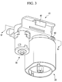
- FIG. 3 is a perspective view showing that a fuel limit vent valve and a rollover valve are connected with a mounting plate of an exemplary fuel supply system according to the present invention.
- FIG. 4 is a cross-sectional view along a line IV-IV of the FIG. 3 .
- FIG. 5 is a drawing showing connection of a mounting plate and a side mounting portion of an exemplary fuel supply system according to the present invention.
- FIG. 6 is a drawing showing connection of a mounting plate and a rear mounting portion of an exemplary fuel supply system according to the present invention.
- FIG. 7 is a partial cross-sectional view showing the inside of an exemplary fuel supply system according to the present invention.
- FIG. 8 is a drawing showing the outside of a fuel tank of an exemplary fuel supply system according to the present invention.
- FIG. 1 , FIG. 2 , and FIG. 3 are respectively a top plan view, a front view, and a perspective view showing that a fuel limit vent valve and a rollover valve are connected with a mounting plate of a fuel supply system according to various embodiments of the present invention.
- FIG. 4 is a cross-sectional view along a line IV-IV of the FIG. 3 .
- a fuel supply system for a vehicle includes a fuel limit vent valve 20 , a rollover valve 30 that is connected with the fuel limit vent valve 20 , and a mounting plate 40 for mounting the fuel limit vent valve 20 and the rollover valve 30 .
- the fuel limit vent valve 20 collects evaporation gas in a fuel tank and supplies the evaporation gas to a canister, and the rollover valve 30 prevents fuel leakage when a vehicle overturns.
- a protruding plate 42 is formed to the mounting plate 40 .
- FIG. 5 is a drawing showing connection of a mounting plate and a side mounting portion of a fuel supply system according to various embodiments of the present invention
- FIG. 6 is a drawing showing connection of a mounting plate and a rear mounting portion of a fuel supply system according to various embodiments of the present invention.
- FIG. 7 is a partial cross-sectional view showing the inside of a fuel supply system according to various embodiments of the present invention
- FIG. 8 is a drawing showing the outside of a fuel tank of a fuel supply system according to various embodiments of the present invention.
- the fuel limit vent valve 20 and the rollover valve 30 are disposed within a fuel tank 10 , and a mounting portion 50 is inwardly protruded within the fuel tank 10 for mounting the mounting plate 40 .
- the mounting portion 50 includes side mounting portions 52 that are symmetrically formed for the mounting plate 40 to be inserted therein, and a rear mounting portion 54 supporting the mounting plate 40 .
- the protruding plate 42 is formed by bending an end portion of the mounting plate 40 , and the side mounting portion 52 and the mounting plate 40 are connected by elastic force of the protruding plate 42 .
- the rear mounting portion 54 supports the mounting plate 40 , and prevents the mounting plate 40 from separating rightward and leftward of FIG. 6 .
- a portion of the fuel tank is inwardly protruded and the fuel limit vent valve 20 and the rollover valve 30 are simultaneously configured therein.
- the fuel tank 10 may be made of a plastic material.
- the fuel limit vent valve 20 and the rollover valve 30 are connected by one evaporation gas exhaust passage 60 , and a connecting passage 62 is formed between the fuel limit vent valve 20 and the rollover valve 30 .
- the evaporation gas exhaust passage 60 is connected with a canister 70 that is disposed outside the fuel tank 10 via a fuel pump module 80 .
- valves disposed inside the fuel supply system can be simply configured and have an evaporation gas exhaust passage in common so that the number of elements can be reduced.
- the weight of fuel in the fuel tank 10 brings a negative pressure in the fuel tank 10 so that the fuel in the evaporation gas exhaust passage 60 may be sucked into the connection passage 62 to prevent the fuel from leaking to the outside.
- the diameter of the connection passage 62 is configured to be sufficiently smaller than the diameter of the evaporation gas exhaust passage 60 .
- the longitudinal axis of the evaporation gas exhaust passage 60 may be disposed lower than a longitudinal axis of the connection passage 62 so that any bubbles that blocks the connection passage 62 while the vehicle rolls over may be removed to increase a siphon effect.
Landscapes
- Engineering & Computer Science (AREA)
- Chemical & Material Sciences (AREA)
- Combustion & Propulsion (AREA)
- Mechanical Engineering (AREA)
- Life Sciences & Earth Sciences (AREA)
- Sustainable Development (AREA)
- Sustainable Energy (AREA)
- Transportation (AREA)
- General Engineering & Computer Science (AREA)
- Cooling, Air Intake And Gas Exhaust, And Fuel Tank Arrangements In Propulsion Units (AREA)
- Supplying Secondary Fuel Or The Like To Fuel, Air Or Fuel-Air Mixtures (AREA)
Abstract
Description
Claims (15)
Applications Claiming Priority (2)
| Application Number | Priority Date | Filing Date | Title |
|---|---|---|---|
| KR1020080080111A KR100969388B1 (en) | 2008-08-14 | 2008-08-14 | Vehicle fuel supply system |
| KR10-2008-0080111 | 2008-08-14 |
Publications (2)
| Publication Number | Publication Date |
|---|---|
| US20100037869A1 US20100037869A1 (en) | 2010-02-18 |
| US8042523B2 true US8042523B2 (en) | 2011-10-25 |
Family
ID=41670883
Family Applications (1)
| Application Number | Title | Priority Date | Filing Date |
|---|---|---|---|
| US12/488,324 Active 2030-05-12 US8042523B2 (en) | 2008-08-14 | 2009-06-19 | Fuel supply system for vehicle |
Country Status (3)
| Country | Link |
|---|---|
| US (1) | US8042523B2 (en) |
| KR (1) | KR100969388B1 (en) |
| CN (1) | CN101648513B (en) |
Cited By (4)
| Publication number | Priority date | Publication date | Assignee | Title |
|---|---|---|---|---|
| US20110101006A1 (en) * | 2009-10-29 | 2011-05-05 | Inergy Automotive Systems Research (Societe Anonyme) | Hollow body comprising an accessory module fastened to the wall thereof, and module suitable for such a hollow body |
| US20150377196A1 (en) * | 2014-03-17 | 2015-12-31 | Kyosan Denki Co., Ltd. | Liquid fuel catcher |
| US9428043B2 (en) * | 2013-11-07 | 2016-08-30 | Fca Us Llc | Liquid vapor separator drain valve |
| US11511622B2 (en) * | 2018-11-30 | 2022-11-29 | Honda Motor Co., Ltd. | Mounting structure for fuel shutoff valve unit |
Families Citing this family (5)
| Publication number | Priority date | Publication date | Assignee | Title |
|---|---|---|---|---|
| US9222450B2 (en) * | 2009-10-09 | 2015-12-29 | Brunswick Corporation | Pressure relief apparatus for use with fuel delivery systems |
| FR3044612B1 (en) * | 2015-12-07 | 2019-08-23 | Continental Automotive France | CONTROL OF DEPRESSURIZATION OF A FUEL TANK OF A MOTOR VEHICLE |
| CN110843507A (en) * | 2018-08-20 | 2020-02-28 | 上海汽车集团股份有限公司 | Vehicles and their high-pressure fuel tanks |
| JP2021066386A (en) * | 2019-10-25 | 2021-04-30 | ヤマハ発動機株式会社 | vehicle |
| CN114290878A (en) * | 2021-12-30 | 2022-04-08 | 中南民族大学 | A vehicle-mounted liquid filter plasma air purification system |
Citations (21)
| Publication number | Priority date | Publication date | Assignee | Title |
|---|---|---|---|---|
| US4960153A (en) * | 1989-11-03 | 1990-10-02 | G. T. Products, Inc. | Fuel tank vapor vent valve |
| US5083583A (en) * | 1990-09-04 | 1992-01-28 | G.T. Products, Inc. | Fuel tank vapor vent valve and seal |
| US5497800A (en) * | 1993-11-05 | 1996-03-12 | Toyoda Gosei Co., Ltd. | Fuel vapor processing device |
| US5535772A (en) * | 1995-05-01 | 1996-07-16 | Stant Manufacturing Inc. | Tank venting control system |
| US5632296A (en) * | 1994-03-28 | 1997-05-27 | Toyoda Gosei Co., Ltd. | Float valve for fuel tank |
| US5687778A (en) * | 1995-05-01 | 1997-11-18 | Stant Manufacturing Inc. | Dual valve tank venting system |
| US5694968A (en) * | 1996-04-15 | 1997-12-09 | Stant Manufacturing Inc. | Tank venting control system |
| KR980001126A (en) | 1996-06-29 | 1998-03-30 | 양재신 | Rollover valve mounting structure of automobile fuel tank |
| US5755252A (en) * | 1994-08-24 | 1998-05-26 | G.T. Products, Inc. | Control valve with two-stage shutoff and peel away opening action |
| US5950655A (en) * | 1997-02-04 | 1999-09-14 | G.T. Products, Inc. | Mechanical seal ORVR system and control valve |
| US6170510B1 (en) * | 1997-05-06 | 2001-01-09 | Stant Manufacturing Inc. | Tank venting control system |
| US6311675B2 (en) * | 1999-04-28 | 2001-11-06 | Walbro Corporation | Vent valve and fuel pump module |
| US6425379B2 (en) * | 1999-12-27 | 2002-07-30 | Kyosan Denki Co., Ltd. | Evaporative emission control system |
| US6520200B1 (en) * | 2001-08-16 | 2003-02-18 | Delphi Technologies, Inc. | Liquid/vapor separator assembly for fuel tank |
| US20030094458A1 (en) * | 2001-11-19 | 2003-05-22 | Sharon Elizabeth Beyer | Fuel delivery module cover assembly |
| US6758235B2 (en) * | 2002-09-30 | 2004-07-06 | Alfmeier Prazision Ag Baugruppen Und Systemlosungen | Vapor control valve with a metallic sealing element |
| US6959721B2 (en) * | 2002-11-21 | 2005-11-01 | Delphi Technologies, Inc. | Cover assembly for fuel delivery module |
| US20060260129A1 (en) * | 2003-09-15 | 2006-11-23 | Eaton Corporation | Mounting a vent valve on a plastic fuel tank |
| US7228847B2 (en) * | 2004-04-30 | 2007-06-12 | Delphi Technologies, Inc. | Cover assembly for fuel tank |
| US7690362B2 (en) * | 2005-10-14 | 2010-04-06 | Continental Automotive Systems Us, Inc. | Flange mounted valve manifold |
| US20100252125A1 (en) * | 2009-04-07 | 2010-10-07 | Delphi Technologies, Inc. | Axially adjustable fill limiter vent valve |
Family Cites Families (4)
| Publication number | Priority date | Publication date | Assignee | Title |
|---|---|---|---|---|
| JP4086592B2 (en) * | 2002-08-30 | 2008-05-14 | 株式会社エフティエス | Fuel tank |
| US7389789B2 (en) * | 2004-01-21 | 2008-06-24 | Raval-Agriculture Cooperative Societies Ltd. | Fuel accessory for fuel tank and method for internally attaching same |
| JP2006131028A (en) * | 2004-11-04 | 2006-05-25 | Aisan Ind Co Ltd | Fuel tank structure of motorcycle |
| CN100519250C (en) * | 2007-03-19 | 2009-07-29 | 重庆宗申技术开发研究有限公司 | Motorcycle oil box |
-
2008
- 2008-08-14 KR KR1020080080111A patent/KR100969388B1/en active Active
-
2009
- 2009-06-19 US US12/488,324 patent/US8042523B2/en active Active
- 2009-07-13 CN CN200910159309.4A patent/CN101648513B/en active Active
Patent Citations (21)
| Publication number | Priority date | Publication date | Assignee | Title |
|---|---|---|---|---|
| US4960153A (en) * | 1989-11-03 | 1990-10-02 | G. T. Products, Inc. | Fuel tank vapor vent valve |
| US5083583A (en) * | 1990-09-04 | 1992-01-28 | G.T. Products, Inc. | Fuel tank vapor vent valve and seal |
| US5497800A (en) * | 1993-11-05 | 1996-03-12 | Toyoda Gosei Co., Ltd. | Fuel vapor processing device |
| US5632296A (en) * | 1994-03-28 | 1997-05-27 | Toyoda Gosei Co., Ltd. | Float valve for fuel tank |
| US5755252A (en) * | 1994-08-24 | 1998-05-26 | G.T. Products, Inc. | Control valve with two-stage shutoff and peel away opening action |
| US5535772A (en) * | 1995-05-01 | 1996-07-16 | Stant Manufacturing Inc. | Tank venting control system |
| US5687778A (en) * | 1995-05-01 | 1997-11-18 | Stant Manufacturing Inc. | Dual valve tank venting system |
| US5694968A (en) * | 1996-04-15 | 1997-12-09 | Stant Manufacturing Inc. | Tank venting control system |
| KR980001126A (en) | 1996-06-29 | 1998-03-30 | 양재신 | Rollover valve mounting structure of automobile fuel tank |
| US5950655A (en) * | 1997-02-04 | 1999-09-14 | G.T. Products, Inc. | Mechanical seal ORVR system and control valve |
| US6170510B1 (en) * | 1997-05-06 | 2001-01-09 | Stant Manufacturing Inc. | Tank venting control system |
| US6311675B2 (en) * | 1999-04-28 | 2001-11-06 | Walbro Corporation | Vent valve and fuel pump module |
| US6425379B2 (en) * | 1999-12-27 | 2002-07-30 | Kyosan Denki Co., Ltd. | Evaporative emission control system |
| US6520200B1 (en) * | 2001-08-16 | 2003-02-18 | Delphi Technologies, Inc. | Liquid/vapor separator assembly for fuel tank |
| US20030094458A1 (en) * | 2001-11-19 | 2003-05-22 | Sharon Elizabeth Beyer | Fuel delivery module cover assembly |
| US6758235B2 (en) * | 2002-09-30 | 2004-07-06 | Alfmeier Prazision Ag Baugruppen Und Systemlosungen | Vapor control valve with a metallic sealing element |
| US6959721B2 (en) * | 2002-11-21 | 2005-11-01 | Delphi Technologies, Inc. | Cover assembly for fuel delivery module |
| US20060260129A1 (en) * | 2003-09-15 | 2006-11-23 | Eaton Corporation | Mounting a vent valve on a plastic fuel tank |
| US7228847B2 (en) * | 2004-04-30 | 2007-06-12 | Delphi Technologies, Inc. | Cover assembly for fuel tank |
| US7690362B2 (en) * | 2005-10-14 | 2010-04-06 | Continental Automotive Systems Us, Inc. | Flange mounted valve manifold |
| US20100252125A1 (en) * | 2009-04-07 | 2010-10-07 | Delphi Technologies, Inc. | Axially adjustable fill limiter vent valve |
Cited By (6)
| Publication number | Priority date | Publication date | Assignee | Title |
|---|---|---|---|---|
| US20110101006A1 (en) * | 2009-10-29 | 2011-05-05 | Inergy Automotive Systems Research (Societe Anonyme) | Hollow body comprising an accessory module fastened to the wall thereof, and module suitable for such a hollow body |
| US9061580B2 (en) * | 2009-10-29 | 2015-06-23 | Inergy Automotive Systems Research (Societe Anonyme) | Hollow body comprising an accessory module fastened to the wall thereof, and module suitable for such a hollow body |
| US9428043B2 (en) * | 2013-11-07 | 2016-08-30 | Fca Us Llc | Liquid vapor separator drain valve |
| US20150377196A1 (en) * | 2014-03-17 | 2015-12-31 | Kyosan Denki Co., Ltd. | Liquid fuel catcher |
| US10035091B2 (en) * | 2014-03-17 | 2018-07-31 | Kyosan Denki Co., Ltd. | Liquid fuel catcher |
| US11511622B2 (en) * | 2018-11-30 | 2022-11-29 | Honda Motor Co., Ltd. | Mounting structure for fuel shutoff valve unit |
Also Published As
| Publication number | Publication date |
|---|---|
| CN101648513A (en) | 2010-02-17 |
| KR100969388B1 (en) | 2010-07-09 |
| KR20100021275A (en) | 2010-02-24 |
| CN101648513B (en) | 2014-04-09 |
| US20100037869A1 (en) | 2010-02-18 |
Similar Documents
| Publication | Publication Date | Title |
|---|---|---|
| US8042523B2 (en) | Fuel supply system for vehicle | |
| JP6049069B2 (en) | Plastic fuel tank with improved creep resistance and manufacturing method thereof | |
| US7311348B1 (en) | Housing apparatus of fuel door | |
| CN108603468B (en) | Fuel tank cover member | |
| US20090133762A1 (en) | Fuel tank | |
| US8844754B2 (en) | Fuel tank having a built-in auxiliary tank | |
| CA2645457C (en) | Fuel tank shell with structural support | |
| US7681557B2 (en) | Canister for vehicle | |
| US10259316B2 (en) | Stiffness reinforcement device for fuel tank of vehicle | |
| CN101469754B (en) | air suspension | |
| KR20050103189A (en) | Fuel tank comprising a support for functional components and support for functional components of a motor vehicle fuel tank | |
| CA2735394C (en) | Vehicle | |
| US7228847B2 (en) | Cover assembly for fuel tank | |
| JP2000229522A (en) | Fuel tank | |
| JP2008240638A (en) | Canister intake / exhaust device and canister intake / exhaust drain container | |
| CN203892074U (en) | Vehicle-mounted refueling oil-gas recovery system and vehicle comprising the same | |
| JP6140635B2 (en) | Fuel supply system | |
| US20180328323A1 (en) | Fuel supply device | |
| US20160076666A1 (en) | Fuel tank valve | |
| US8511503B2 (en) | Fuel tank | |
| JP7267152B2 (en) | fuel supply | |
| US20180017023A1 (en) | Fuel system having vent point valve | |
| JP2009236061A (en) | Fuel supply apparatus | |
| JP4285275B2 (en) | Car body rear structure | |
| US7343903B2 (en) | Fuel tank |
Legal Events
| Date | Code | Title | Description |
|---|---|---|---|
| AS | Assignment |
Owner name: HYUNDAI MOTOR COMPANY,KOREA, REPUBLIC OF Free format text: ASSIGNMENT OF ASSIGNORS INTEREST;ASSIGNOR:LEE, SUNGWON;REEL/FRAME:022852/0098 Effective date: 20090616 Owner name: KIA MOTORS CORPORATION,KOREA, REPUBLIC OF Free format text: ASSIGNMENT OF ASSIGNORS INTEREST;ASSIGNOR:LEE, SUNGWON;REEL/FRAME:022852/0098 Effective date: 20090616 Owner name: HYUNDAI MOTOR COMPANY, KOREA, REPUBLIC OF Free format text: ASSIGNMENT OF ASSIGNORS INTEREST;ASSIGNOR:LEE, SUNGWON;REEL/FRAME:022852/0098 Effective date: 20090616 Owner name: KIA MOTORS CORPORATION, KOREA, REPUBLIC OF Free format text: ASSIGNMENT OF ASSIGNORS INTEREST;ASSIGNOR:LEE, SUNGWON;REEL/FRAME:022852/0098 Effective date: 20090616 |
|
| STCF | Information on status: patent grant |
Free format text: PATENTED CASE |
|
| FEPP | Fee payment procedure |
Free format text: PAYOR NUMBER ASSIGNED (ORIGINAL EVENT CODE: ASPN); ENTITY STATUS OF PATENT OWNER: LARGE ENTITY |
|
| FPAY | Fee payment |
Year of fee payment: 4 |
|
| MAFP | Maintenance fee payment |
Free format text: PAYMENT OF MAINTENANCE FEE, 8TH YEAR, LARGE ENTITY (ORIGINAL EVENT CODE: M1552); ENTITY STATUS OF PATENT OWNER: LARGE ENTITY Year of fee payment: 8 |
|
| MAFP | Maintenance fee payment |
Free format text: PAYMENT OF MAINTENANCE FEE, 12TH YEAR, LARGE ENTITY (ORIGINAL EVENT CODE: M1553); ENTITY STATUS OF PATENT OWNER: LARGE ENTITY Year of fee payment: 12 |