US8036521B2 - Image pickup apparatus and focus control method - Google Patents
Image pickup apparatus and focus control method Download PDFInfo
- Publication number
- US8036521B2 US8036521B2 US12/592,765 US59276509A US8036521B2 US 8036521 B2 US8036521 B2 US 8036521B2 US 59276509 A US59276509 A US 59276509A US 8036521 B2 US8036521 B2 US 8036521B2
- Authority
- US
- United States
- Prior art keywords
- focus
- reliability
- driving
- focus lens
- pixel group
- Prior art date
- Legal status (The legal status is an assumption and is not a legal conclusion. Google has not performed a legal analysis and makes no representation as to the accuracy of the status listed.)
- Active
Links
Images


Classifications
-
- G—PHYSICS
- G03—PHOTOGRAPHY; CINEMATOGRAPHY; ANALOGOUS TECHNIQUES USING WAVES OTHER THAN OPTICAL WAVES; ELECTROGRAPHY; HOLOGRAPHY
- G03B—APPARATUS OR ARRANGEMENTS FOR TAKING PHOTOGRAPHS OR FOR PROJECTING OR VIEWING THEM; APPARATUS OR ARRANGEMENTS EMPLOYING ANALOGOUS TECHNIQUES USING WAVES OTHER THAN OPTICAL WAVES; ACCESSORIES THEREFOR
- G03B13/00—Viewfinders; Focusing aids for cameras; Means for focusing for cameras; Autofocus systems for cameras
-
- H—ELECTRICITY
- H04—ELECTRIC COMMUNICATION TECHNIQUE
- H04N—PICTORIAL COMMUNICATION, e.g. TELEVISION
- H04N23/00—Cameras or camera modules comprising electronic image sensors; Control thereof
- H04N23/60—Control of cameras or camera modules
- H04N23/67—Focus control based on electronic image sensor signals
- H04N23/672—Focus control based on electronic image sensor signals based on the phase difference signals
-
- H—ELECTRICITY
- H04—ELECTRIC COMMUNICATION TECHNIQUE
- H04N—PICTORIAL COMMUNICATION, e.g. TELEVISION
- H04N23/00—Cameras or camera modules comprising electronic image sensors; Control thereof
- H04N23/60—Control of cameras or camera modules
- H04N23/67—Focus control based on electronic image sensor signals
- H04N23/673—Focus control based on electronic image sensor signals based on contrast or high frequency components of image signals, e.g. hill climbing method
Definitions
- the present invention relates to an image pickup apparatus having an imaging element with a first pixel group that realizes a pupil-dividing function.
- phase difference AF phase difference detection system
- Japanese Published Patent Application No. 2008-147821 discloses an image pickup apparatus provided with an imaging element having a plurality of pixel pairs for phase difference AF in which the centers of openings of the respective light-shielding plates are oppositely biased from each other with respect to the center of a microlens (hereinafter, also referred to as an imaging element with phase-difference detection function).
- an image pickup apparatus is configured such that a distance from a subject can be performed by allowing pixels for phase difference AF to receive light fluxes passed through a pair of portion areas on an exit pupil of a photographic lens.
- the image pickup apparatus of the above patent document employs the imaging element with phase-difference detection function, allegedly having a comparatively small range of allowable distance measurement. Therefore, if the amount of defocus is large when starting the AF operation (significantly blurred state), focusing is out of an allowable range of distance measurement and the phase difference AF becomes difficult to be carried out. In such a case, a lens drive will be carried out until a focus lens goes into an allowable range of distance measurement. However, if the lens is driven in the opposite direction from the point of focus, a quick AF operation (focus control) will become difficult.
- a first embodiment of the present invention is an image pickup apparatus that includes: a drive control section controlling driving of a focus lens from a first position to a second position in a photographic optical system; an imaging element having a first pixel group realizing a pupil-dividing function by receiving light fluxes from a subject passing through a pair of portion areas oppositely biased from each other in a predetermined direction on an exit pupil in the photographic optical system and a second pixel group without the pupil-dividing function; and a focus control section driving the focus lens toward an in-focus position detected by focus detection of a phase-difference detection system from a pixel signal of the first pixel group.
- the section controlling focusing includes: a focus-direction detecting section, a determination section, a first control section, and a second control section.
- the focus-direction detecting section is provided for detecting the in-focus position by making a comparison between first information and second information, where the first information is obtained as focus detection information to be used for focus detection of a contrast detection system based on a pixel signal generated from the second pixel group when the focus lens is located at the first position, and the second information is obtained as the focus detection information based on a pixel signal generated from the second pixel group when the focus lens is located at the second position.
- the determination section is provided for determining reliability of detecting the in-focus position depending on whether or not the pixel signal from the first pixel group satisfies a predetermined condition.
- the first control section is provided for driving the focus lens toward an in-focus position detected based on the pixel signal from the first pixel group when the determination section determines that the pixel signal from the first pixel group satisfies the predetermined condition and the reliability is high.
- the second control section is provided for driving the focus lens toward an in-focus position detected by the focus-direction detecting section when the determination section determines that the pixel signal from the first pixel group does not satisfy the predetermined condition and the reliability is low.
- a second embodiment of the present invention is a focus control method that includes the steps of: controlling driving of a focus lens from a first position to a second position in a photographic optical system (step of drive control); and receiving light fluxes from a subject passing through a pair of portion areas oppositely biased from each other in a predetermined direction on an exit pupil in the photographic optical system, and then driving the focus lens toward an in-focus position detected by focus detection of a phase-difference detection system from a pixel signal from a first pixel group of an imaging element that realizes a pupil-dividing function (step of focus control).
- the step of focus control includes the substeps detecting the in-focus position by making a comparison between first information and second information, where the first information is obtained as focus detection information to be used for focus detection of a contrast detection system based on a pixel signal generated from the second pixel group of the imaging element without the pupil-dividing function when the focus lens is located on the first position, and the second information is obtained as the focus detection information based on a pixel signal generated from the second pixel group when the focus lens is located at the second position (substep of in-focus direction detection); determining reliability of detecting the in-focus position depending on whether or not the pixel signal from the first pixel group satisfies a predetermined condition (substep of determination); driving the focus lens toward an in-focus position detected based on the pixel signal from the first pixel group when the determination means determines that the pixel signal from the first pixel group satisfies the predetermined condition and the reliability is high (substep of first control); and driving the focus lens toward an in-focus position detected by the
- a first pixel group for realizing a pupil-dividing function by receiving light fluxes from a subject passing through a pair of portion areas oppositely biased from each other in a predetermined direction on an exit pupil in the photographic optical system.
- a second pixel group without the pupil-dividing function is also provided. If it is determined that the pixel signal from the first pixel group satisfies a predetermined condition and the reliability of the detection of in-focus position is high, a focus lens is driven toward an in-focus position detected by focus detection of a phase-difference detection system based on a pixel signal of the first pixel group.
- the focus lens is driven in the direction of an in-focus position detected by making a comparison between the first information and the second information obtained as focus detection information used for focus detection with a contrast detection system on the basis of a pixel signal generated from the second pixel group when the focus lens is located on each of the first position and the second position.
- FIG. 1 is a diagram illustrating an external configuration of an image pickup apparatus according to an embodiment of the present invention
- FIG. 2 is a diagram illustrating an external configuration of the image pickup apparatus according to the embodiment of the present invention.
- FIG. 3 is a longitudinal cross-sectional view of the image pickup apparatus
- FIG. 4 is a block diagram illustrating an electrical configuration of the image pickup apparatus
- FIG. 5 is a schematic diagram illustrating the configuration of an imaging element
- FIG. 6 is a schematic diagram illustrating the configuration of the imaging element
- FIG. 7 is a schematic diagram illustrating the configuration of the imaging element
- FIG. 8 is a schematic diagram illustrating a multi-area on the imaging element
- FIG. 9 is a schematic diagram illustrating a principle of a phase difference AF using an AF line
- FIG. 10 is a graphic diagram conceptually illustrating a case of when a focal plane is defocused by 10 mm advancing close to an imaging surface
- FIG. 11 is a graphic diagram conceptually illustrating a case of when a focal plane is defocused by 200 ⁇ m advancing close to the imaging surface;
- FIG. 12 is a graphic diagram conceptually illustrating a case of when a focal plane is defocused by 100 ⁇ m advancing close to the imaging surface;
- FIG. 13 is a graphic diagram conceptually illustrating an in-focus state where the focal plane coincides with the imaging surface
- FIG. 14 is a graphic diagram conceptually illustrating a case of when the focal plane is defocused by 100 ⁇ m or more advancing away from the imaging surface;
- FIG. 15 is a graphic diagram conceptually illustrating a case of when the focal plane is defocused by 200 ⁇ m or more advancing away from the imaging surface;
- FIG. 16 is a graphic diagram conceptually illustrating a case of when the focal plane is defocused by 10 mm or more advancing away from the imaging surface;
- FIG. 17 is a graphic diagram illustrating the relationship between the amount of shift and the amount of defocus
- FIG. 18 is a graphic diagram illustrating the principle of contrast AF
- FIG. 19 is a flowchart illustrating a basic operation of the image pickup apparatus
- FIG. 20 is a flowchart illustrating a basic operation of the image pickup apparatus
- FIG. 21 is a flowchart illustrating the detecting operation in the in-focus direction with the contrast AF
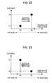
- FIG. 22 is a diagram illustrating the detection of the in-focus direction with the contrast AF.
- FIG. 23 is a diagram illustrating the detection of the in-focus direction with the contrast AF.
- FIG. 1 and FIG. 2 are diagrams showing an external configuration of an image pickup apparatus 1 according to a first embodiment of the present invention.
- FIG. 1 is a front view
- FIG. 2 is a rear view of the image pickup apparatus 1 .
- a vertical cross-sectional view of the image pickup apparatus 1 is illustrated in FIG. 3 .
- the image pickup apparatus 1 may be a digital SLR still camera.
- the image pickup apparatus 1 includes a camera body 10 and a photographic lens 2 serving as an interchangeable lens removably attached to the camera body 10 .
- FIG. 1 on the front side of the camera body 1 , there are a mount portion 301 to which the photographic lens 2 is attached; a lens replacement button 302 arranged on the right-lateral side of the mount portion 301 ; and a grip portion 303 protruded from the front left end portion (the left side in the X direction) to allow a user to securely hold the camera body 10 by one hand (or both hands).
- the camera body 10 is provided with a mode setting dial 305 on the upper left front portion (upper left side in the Y direction), a control value setting dial 306 on the upper right front portion, and a shatter button 307 on the upper surface of the grip portion 303 .
- a liquid crystal display (LCD) 311 In FIG. 2 , a liquid crystal display (LCD) 311 , setting buttons 312 , a cross-key selector 314 , and a push button 315 are provided on a rear surface of the camera body 10 .
- the setting buttons 312 are located on the left side of the LCD 311
- the cross-key selector 314 is located on the right side of the LCD 311 .
- the push button 315 is located at the center of the cross-key selector 314 .
- an electronic viewfinder (EVF) 316 is disposed at an upper position with respect to the LCD 311 .
- the eye cup 321 is formed around the EVF 316 .
- the main switch 317 is disposed on the left side of the EVF 316 .
- the exposure correction button 323 and the AE lock button 324 are disposed on the right side of the EVF 316 .
- the flash unit 318 and the connection terminal portion 319 are located in an upper portion of the EVF 316 .
- the mount portion 301 is provided with a plurality of electrical contacts for electrical connection with the attached photographic lens 2 , a coupler for mechanical connection, and so on.
- the lens replacement button 302 is a button which is pressed to remove the photographic lens 2 attached to the mount portion 301 .
- the grip portion 303 is a portion with which a user holds the image pickup apparatus 1 during a shooting operation, and has finger-shaped contours for a more fitting experience.
- the battery storage room and the card storage room (un-illustrating) are established in the inside of grip part 303 .
- the battery receiving chamber is designed to receive a battery 69 B (see FIG. 4 ) serving as a camera power source, and the card receiving chamber is designed to removably receive a recording medium, a memory card 67 (see FIG. 4 ), to record image data of photographed images onto the memory card 67 .
- the grip portion 303 may be provided with a grip sensor configured to detect whether or not a user holds the grip portion 303 .
- Each of the mode setting dial 305 and the control value setting dial 306 is formed of a substantially disk-shaped member rotatable in a plane substantially parallel to the top surface of the camera body 10 .
- the mode setting dial 305 is operable to select one of modes or functions provided in the image pickup apparatus 1 , such as an Auto Exposure (AE) control mode, an Auto Focus (AF) control mode, various shooting modes such as a still-image shooting mode for shooting a still image and a continuous shooting mode for continuously shooting images, and a reproduction mode for reproducing a recorded image.
- the control value setting dial 306 is arranged to set a control value for each of the functions provided in the image pickup apparatus 1 .
- the shutter button 307 is a pressing switch which can be pressed halfway (“half-pressed”) and which can further be pressed (“fully pressed”).
- a pre-shooting operation before shooting a still image of a subject (a pre-shooting operation including setting of an exposure control value and focus adjustment or focusing) is executed.
- a shooting operation (a series of operations of exposing an imaging element 101 (see FIG. 3 ) to light, applying predetermined image processing to an image signal obtained by the exposure, and recording the resulting image signal onto a recording medium such as a memory card) is executed.
- the LCD 311 includes a color liquid crystal panel capable of displaying an image.
- the LCD 311 is configured to display an image captured by the imaging element 101 (see FIG. 3 ) or to reproduce and display a recorded image, and is also configured to display a setting screen for setting the functions or modes provided in the image pickup apparatus 1 .
- the setting buttons 312 are buttons which are operated to perform the functions provided in the image pickup apparatus 1 .
- Examples of the setting buttons 312 include a selection setting switch for setting an item selected on a menu screen displayed on the LCD 311 , a selection cancellation switch, a menu display switch for switching the display on the menu screen, a display on/off switch, and a display magnification switch.
- the cross key sector 314 has an annular member provided with a plurality of pressing parts (portions marked by triangles in the figure) arranged with constant intervals in the circumferential direction.
- the cross key sector 314 is constituted so that the pressing operation of a pressing part will be detected by a contact point, a switch (not shown), that corresponds to each pressing part.
- the push button 315 is located at the center of the cross-key selector 314 .
- the cross-key selector 314 and the push button 315 are operable to enter instructions, such as an instruction to change the shooting magnification to move a zoom lens 212 in a wide-angle (wide) direction or a telephoto (tele) direction, an instruction to set the frame advance feature for advancing frame-by-frame a recorded image to be reproduced on the LCD 311 , and an instruction to set shooting conditions (such as the aperture value, the shutter speed, and the turning on or off of flash light).
- the EVF 316 includes, for example, a color liquid crystal panel (not shown) which can display an image.
- the EVF 316 is configured to display an image captured by the imaging element 101 (see FIG. 3 ) or to reproduce and display a recorded image.
- live-view (preview) display Prior to actual shooting (shooting for image recording), live-view (preview) display is provided so that a subject can appear on the EVF 316 or the LCD 311 in a movie form on the basis of image signals sequentially generated by the imaging element 101 . This allows a user to visually check the subject to be actually photographed by the imaging element 101 .
- the main switch 317 is formed of a two-contact slide switch slidable to the right and left. When the main switch 317 is set to the right in FIG. 2 , the image pickup apparatus 1 is powered on. When the main switch 317 is set to the left, the image pickup apparatus 1 is powered off.
- the flash unit 318 is formed as a pop-up built-in flashlight.
- An external flashlight or the like may be attached to the camera body 10 using the connection terminal portion 319 .
- the eye cup 321 is a substantially C-shaped light-shielding member having light-shielding properties and capable of blocking external light from entering the EVF 316 .
- the exposure correction button 323 is a button for manually adjusting the exposure value (aperture value or shutter speed).
- the AE lock button 324 is a button for fixing the exposure.
- the photographic lens 2 serves as a lens window through which light (optical image) coming from the subject is received, and also serves as a photographic optical system for directing the subject light into the imaging element 101 provided in the camera body 10 .
- the photographic lens 211 can be removed from the camera body 10 by pressing the lens replacement button 302 described above.
- the photographic lens 2 includes a lens group 21 having a plurality of lenses arranged in series along an optical axis LT (see FIG. 3 ).
- the lens group 21 includes a focus lens 211 (see FIG. 4 ) configured to perform focus adjustment, and the zoom lens 212 (see FIG. 4 ) configured to perform variable magnification.
- the focus lens 211 and the zoom lens 212 are driven in the direction of the optical axis LT (see FIG. 3 ) to perform focus adjustment and variable magnification, respectively.
- the photographic lens 2 further includes an operating ring at an appropriate position on an outer circumference of a barrel of the photographic lens 2 so as to be rotatable along the outer circumferential surface of the barrel.
- the zoom lens 212 moves in the direction of the optical axis LT depending on the direction of rotation and the amount of rotation of the operating ring, and is set to a zoom magnification (shooting magnification) corresponding to the position to which the zoom lens 212 moves.
- the imaging element 101 is arranged in the direction perpendicular to the optical axis LT of the lens group 21 that constitutes the photographic lens 2 when the photographic lens is attached to the camera body 10 .
- the image element 101 may be a complementary metal-oxide semiconductor (CMOS) color area sensor (CMOS imaging element) where, for example, a plurality of pixels having photodiodes is two-dimensionally arranged in a matrix and the respective pixels are provided with red (R), green (G), and blue (B) color filters having different spectral characteristics.
- CMOS complementary metal-oxide semiconductor
- CMOS imaging element CMOS imaging element
- the imaging element (imaging sensor) 101 generates analog electrical signals (image signals) of red (R), green (G), and blue (B) color components regarding a subject optical image formed through the photographic lens (photographic optical system) 2 , and outputs them as R, G, and B color image signals.
- image signals image signals
- RGB red
- G green
- B blue
- the details of the configuration of this imaging element 101 will be described later.
- the imaging element 101 is held on an image element driving mechanism 200 movably in two dimensional directions on the plane perpendicular to the optical axis L.
- a shutter unit is placed in front of the imaging element 101 in the optical axis direction.
- the shutter unit 40 includes a curtain (not shown) that moves up and down and is formed as a mechanical focal plane shutter configured to perform an optical path opening operation and optical path blocking operation of the subject light directed toward the imaging element 101 along the optical axis L. If the imaging element 101 is an imaging element that can be completely electronically shuttered, the shutter unit 40 may be omitted.
- FIG. 4 is a block diagram illustrating an electrical configuration of the entire image pickup apparatus 1 .
- members that are the same as or similar to those shown in FIGS. 1 to 3 are assigned the same reference numerals.
- the electrical configuration of the photographic lens 2 will be described first.
- the photographic lens 2 includes, in addition to the lens group 21 forming the photographic optical system described above, a lens driving mechanism 24 , a lens position detection unit 25 , a lens control unit 26 , and an aperture driving mechanism 27 .
- the focus lens 211 , the zoom lens 212 , and an aperture 23 configured to adjust the amount of light incident on the imaging element 101 in the camera body 10 are held in the direction of the optical axis LT (see FIG. 3 ) within the barrel.
- an optical image of the subject is received and formed on the imaging element 101 .
- Focusing operation is performed such that an AF actuator 71 M in the camera body 10 drives the lens group 21 in the direction of the optical axis LT.
- the lens driving mechanism 24 includes, for example, a helicoid and a gear (not shown) that causes the helicoid to rotate.
- the lens driving mechanism 24 drives the focus lens 211 or any other suitable component in a direction parallel to the optical axis LT.
- the direction of movement and the amount of movement of the focus lens 211 are determined according to the direction of rotation and the rotational speed of the AF actuator 71 M, respectively.
- the lens position detection unit 25 includes an encoder plate and an encoder brush.
- the encoder plate has a plurality of code patterns defined at predetermined pitches in the direction of the optical axis LT within a movable range of the lens group 21 .
- the encoder brush moves along with the barrel 22 in slidable contact with the encoder plate.
- the lens position detection unit 25 is configured to detect the amount of movement of the lens group 21 during focus control.
- a lens position detected by the lens position detection unit 25 is output as, for example, the number of pulses.
- the lens control unit 26 includes, for example, a microcomputer having a built-in memory (not shown) such as a read-only memory (ROM) that stores a control program or a flash memory that stores data regarding status information.
- a microcomputer having a built-in memory (not shown) such as a read-only memory (ROM) that stores a control program or a flash memory that stores data regarding status information.
- ROM read-only memory
- the lens control unit 26 has a communication function of performing communication with the main control unit 62 of the camera body 10 through a connector Ec.
- the status information data of the lens group 21 such as the focal length, the exit pupil position, the aperture value, the in-focus distance, and the amount of ambient light, can be transmitted to the main control unit 62 .
- data regarding the amount of driving of the focus lens 211 can be received from the main control unit 62 .
- the data of the focal length information about the photographic lens 2 , the position of the focus lens 211 , the aperture value, and so on can be transmitted to main control unit 62 .
- the aperture driving mechanism 27 is configured to change the aperture diameter of the aperture 23 in response to a driving force received from an aperture driving actuator 73 M through the coupler 75 .
- the camera body 10 includes, in addition to the components described above, such as the imaging element 101 and the shutter unit 40 , an analog front end (AFE) 5 , an image processing unit 61 , an image memory 614 , the main control unit 62 , a flash circuit 63 , an operation unit 64 , video random access memories (VRAMs) 65 ( 65 a and 65 b ), a card interface (I/F) 66 , a memory card 67 , a communication I/F 68 , a power supply circuit 69 , a battery 69 B, a focus driving control unit 71 A, an AF actuator 71 M, a shutter driving control unit 72 A, a shutter driving actuator 72 M, an aperture driving control unit 73 A, and an aperture driving actuator 73 M.
- AFE analog front end
- VRAMs video random access memories
- I/F card interface
- the imaging element 101 is formed of a CMOS sensor.
- a timing control circuit 51 controls an imaging operation such as the start (and end) of the exposure operation of the imaging element 101 , the output selection of individual pixels included in the imaging element 101 , and the reading of pixel signals.
- the AFE 5 is configured to supply timing pulses to the imaging element 101 to perform a predetermined operation, and to apply predetermined signal processing to image signals output from the imaging element 101 (a group of analog signals corresponding to beams of light received by the individual pixels of the CMOS area sensor) to convert them into digital signals, which are then output to the image processing unit 61 .
- the AFE 5 includes the timing control circuit 51 , a signal processing unit 52 , and an analog-to-digital (A/D) conversion unit 53 .
- the timing control circuit 51 generates predetermined timing pulses (such as a vertical scanning pulse ⁇ Vn, a horizontal scanning pulse ⁇ Vm, and a pulse for generating a reset signal ⁇ Vr) on the basis of a reference clock signal output from the main control unit 62 , and outputs them to the imaging element 101 to control the imaging operation of the imaging element 101 .
- predetermined timing pulses such as a vertical scanning pulse ⁇ Vn, a horizontal scanning pulse ⁇ Vm, and a pulse for generating a reset signal ⁇ Vr
- the signal processing unit 52 is configured to apply predetermined analog signal processing to analog image signals output from the imaging element 101 .
- the signal processing unit 52 includes a correlated double sampling (CDS) circuit, an automatic gain control (AGC) circuit that amplifies a charge signal from the imaging element 101 , and a clamp circuit.
- CDS correlated double sampling
- AGC automatic gain control
- charge signals (pixel signals) from the respective pixels (G pixels 11 gb , R pixels 11 r , and B pixels 11 b ) generally arranged on pixel lines Ln described later are amplified with a gain (amplification factor) of ⁇ .
- charge signals from the respective pixels along an AF line Lf described later are amplified with gain of ⁇ ( ⁇ > ⁇ ).
- the sensitivities thereof will fall compared with the usual pixels for photography. Therefore, it is necessary to amplify the signals with a gain higher than the usual to secure a proper output level.
- the A/D conversion unit 53 is configured to convert analog R, G, and B image signals output from the signal processing unit 52 into digital image signals having a plurality of bits (for example, 12 bits) on the basis of timing pulses output from the timing control circuit 51 .
- the image processing unit 61 is configured to perform predetermined signal processing on image data output from the AFE 5 to create an image file.
- the image processing unit 61 includes a black level correction circuit 611 , a white balance control circuit 612 , and a gamma correction circuit 613 .
- the image data which the image data taken into image processing unit 61 is once written in image memory 614 synchronizing with read-out of the imaging element 101 . Subsequently, the image data written in this image memory 614 is accessed and then processed in each block of the image processing unit 61 .
- the black level correction circuit 611 is configured to correct the black level of the A/D converted digital R, G, and B image signals obtained by the A/D conversion unit 53 into a reference black level.
- the white balance control circuit 612 is configured to perform level conversion (white balance (WB) adjustment) of the digital signals of the red (R), green (G), and blue (B) color components on the basis of reference white in accordance with a light source. That is, based on WB adjustment data supplied from the main control unit 62 , the white balance control circuit 612 specifies a portion that is estimated to be a white portion in the photographed subject from the luminance or chroma data. Then the white balance control circuit 612 determines a mean of the R, G, and B color components in the specified portion, as well as a G/R ratio and a G/B ratio. The mean, the G/R ratio, and the G/B ratio are used as R and B correction gains to perform level correction.
- WB white balance
- the gamma correction circuit 613 is configured to correct grayscale characteristics of the WB-adjusted image data. Specifically, the gamma correction circuit 613 performs non-linear transformation on the levels of the image data using a gamma correction table that is set in advance for each of the color components, and also performs offset adjustment.
- the image memory 614 is a memory that, in a shooting mode, temporarily stores image data output from the image processing unit 61 and that is used by the main control unit as a work area for performing a predetermined process on the image data. In a reproduction mode, the image memory 614 temporarily stores image data read from the memory card 67 .
- the main control unit 62 includes, for example, a microcomputer having a built-in storage unit such as a ROM that stores a control program or a flash memory that temporarily stores data, and is configured to control the operation of individual components of the image pickup apparatus 1 .
- a microcomputer having a built-in storage unit such as a ROM that stores a control program or a flash memory that temporarily stores data, and is configured to control the operation of individual components of the image pickup apparatus 1 .
- the main control unit 62 determines the direction of shaking and the amount of shaking on the basis of a shaking detection signal from a shaking detection sensor (not shown) when a hand-shake correction mode is performed.
- the main control unit 62 Based on the determined direction and amount of shaking, the main control unit 62 generates and outputs a shake-correction control signal to the image element driving mechanism 200 . Then, the imaging element 101 is driven by the imaging element driving mechanism 200 and moved in the direction of canceling the hand shaking.
- the flash circuit 63 is configured to, in a flash shooting mode, control the amount of light emitted from the flash unit 318 or an external flashlight connected to the connection terminal portion 319 to an amount of light designated by the main control unit 62 .
- the operation unit 64 includes the mode setting dial 305 , the control value setting dial 306 , the shutter button 307 , the setting buttons 312 , the cross-key selector 314 , the push button 315 , and the main switch 317 , described above, and is configured to input operation information to the main control unit 62 .
- the VRAMs 65 a and 65 b are buffer memories having a storage capacity of image signals corresponding to the number of pixels of the LCD 311 and the EVF 316 , respectively, and are provided between the main control unit 62 and the LCD 311 and between the main control unit 62 and the EVF 316 , respectively.
- the card I/F 66 is an interface that allows transmission and reception of signals between the memory card and the main control unit 62 .
- the memory card 67 is a recording medium on which image data generated by the main control unit 62 is stored.
- the communication I/F 68 is an interface configured to allow transmission of image data and other suitable data to a personal computer or any other suitable external device.
- the power supply circuit 69 is formed of, for example, a constant voltage circuit, and generates a voltage for driving the overall image pickup apparatus 1 including a control unit, such as the main control unit 62 , the imaging element 101 , and various other driving units.
- the imaging element 101 is energized under control of a control signal supplied from the main control unit 62 to the power supply circuit 69 .
- the battery 69 B includes a primary battery such as an alkaline battery and a secondary battery such as a nickel metal-hydride rechargeable battery, and serves as a power source that supplies power to the overall image pickup apparatus 1 .
- Focus driving control unit 71 A is configured to generate a drive control signal for the AF actuator 71 M, which is used for moving the focus lens 211 to an in-focus position, on the basis of an AF control signal supplied from the main control unit 62 .
- the AF actuator 71 M includes a stepping motor and provides the lens driving mechanism 24 of the photographic lens 2 with a lens-driving force through the coupler 74 .
- the AF actuator 71 M may be installed in the interchangeable photographic lens 2 in stead of in the camera body 10 .
- the shutter driving control unit 72 A is configured to generate a drive control signal for the shutter driving actuator 72 M on the basis of a control signal supplied from the main control unit 62 .
- the shutter driving actuator 72 M is an actuator that drives the shutter unit 40 to open and close.
- the aperture driving control unit 73 A is configured to generate a drive control signal for the aperture driving actuator 73 M on the basis of a control signal supplied from the main control unit 62 .
- the aperture driving actuator 73 M applies a driving force to the aperture driving mechanism 27 through the coupler 75 .
- the camera body 10 further includes a phase difference AF calculation circuit 76 and a contrast AF calculation circuit 77 that perform calculations used for the autofocus (AF) control on the basis of the black-level-corrected image data output from the black level correction circuit 611 .
- the image pickup apparatus 1 is configured to perform phase difference AF in which transmitted light beams transmitted (passing) through different portions of an exit pupil are received by the imaging element 101 .
- the configuration of the imaging element 101 and the principle of phase difference AF using the imaging element 101 will now be described.
- FIGS. 5 and 6 are diagrams illustrating the configuration of the imaging element 101 .
- the imaging element 101 is configured to perform a distance measurement by focus detection with a phase difference detection system in an AF area (focus detection area) Ef (Efa) specified in the center of an imaging surface 101 f (see FIG. 5 ).
- AF lines Lf are horizontally formed on the imaging element 101 and have a pupil-dividing function to carry out the phase difference AF (the details thereof will be described later).
- a distance measurement with respect to a subject can be performed in the AF area Efa defined as a region containing the partial sections of the respective AF lines Lf.
- the AF area Ef includes a group of normal pixels (second pixel group) having no pupil-dividing function and constructed of R pixels 111 , G pixels 112 , and B pixels 113 configured such that red (R), green (G), and blue (B) color filters are disposed on photodiodes (hereinafter, such pixels will be simply referred to as “normal pixels”).
- the AF area Ef includes a pixel-pair group 11 f for carrying out the phase difference AF, having light-shielding plates 12 a and 12 b (shaded portions) described later (hereinafter, simply referred to as an “AF pixel pair”).
- the AF area Ef includes a Gr line L 1 in which G pixels 112 and R pixels 111 are alternately arranged in the horizontal direction and a Gb line L 2 in which B pixels 113 and G pixels 112 are alternately arranged in the horizontal direction. Both the Gr line L 1 and the Gb line L 2 form horizontal lines of normal pixels 110 (normal pixel lines), respectively. The Gr lines L 1 and Gb lines L 2 are alternately arranged in the vertical direction to form the Bayer arrangement.
- the AF lines (focus detection pixel rows) Lf are formed such that the AF pixel pairs 11 f are horizontally arranged in rows.
- the AF lines Lf are next to each other in the vertical direction and periodically formed in the vertical direction such that, as shown in FIG. 7 , 10 normal pixel lines Ln are sandwiched between the AF lines Lf.
- AF areas Efb each having a group of AF pixel pairs 11 f and a group of normal pixels 110 may be further constructed around the AF area Efa (see FIG. 8 ).
- AF areas focus detection areas
- FIG. 8 an AF mode in which one AF area (hereinafter, also referred to as a “single area”) Ef as shown in FIG. 5 and another AF mode in which nine AF areas (hereinafter, also referred to as a “multi-area”) Ef as shown in FIG. 8 can be specified by user input on the setting screen displayed, for example, on the LCD 311 .
- FIG. 9 is a diagram illustrating the principle of the phase difference AF using the AF lines Lf.
- Two or more sets of pixels 11 a and 11 b having the light-shielding plates 12 a and 12 b are horizontally arranged on the AF line Lf so that the opening OP of the light-shielding plate 12 a and the opening OP of the light-shielding plate 12 b are formed in mirror symmetry with respect to each other.
- the openings OP are responsible for separating light flux Ta from the right side portion Qa of the exit pupil and light flux Tb from the left side portion Qb thereof of the interchangeable lens 2 .
- the pixel 11 a has the light-shielding plate 12 a in which a slit-shaped opening OP is biased to the right side with respect to the photoelectric conversion part (photodiode) PD directly below the plate 12 a (hereinafter, such a pixel is also referred to as a “first AF pixel”).
- the pixel 11 b has the light-shielding plate 12 b in which a slit-shaped opening OP is biased to the left side with respect to the photoelectric conversion part (photodiode) PD directly below the plate 12 b (hereinafter, such a pixel is also referred to as a “second AF pixel”).
- the pixels 11 a and the pixels 11 b are alternately arranged on the AF line Lf (see FIG. 6 ). Therefore, the photoelectric conversion part PD of the first AF pixel 11 a receives the light flux Ta from the right side portion Qa of the exit pupil, passing through a microlens ML and the opening OP of the light-shielding plate 12 a . Also, the photoelectric conversion part PF of the second AF pixel 11 b receives the light flux Tb from the left side portion Qb of the exit pupil, passing through a microlens ML and the opening OP of the light-shielding plate 12 b .
- the AF pixel pair 11 f constructed of the first AF pixel 11 a and the second AF pixel 11 b is allowed to receive the light fluxes Ta and Tb from a subject passing through the right and left side portions (a pair of portion areas) Qa and Qb horizontally arranged on the opposite sides of the exit pupil of the interchangeable lens 2 . Therefore, a pupil-dividing function can be realized by the AF line LF constructed of a group of such AF pixel pairs 11 f (first pixel group).
- the pixel output of the first AF pixel 11 a is referred to as an “A-type pixel output”
- the pixel output of the second AF pixel 11 b is referred to as a “B-type pixel output”.
- FIGS. 10 to 16 for example, the relationship between the A-type pixel output and the B-type pixel output, which are obtained from the pixel arrangement of the AF pixel pairs 11 f on one of the AF lines Lf will be described.
- FIG. 10 is a graphic diagram conceptually illustrating a case of when the focal plane is defocused by 10 mm or more advancing close to the imaging surface 101 f of the imaging element 101 .
- FIG. 11 is a graphic diagram conceptually illustrating a case of when the focal plane is defocused by 100 ⁇ m advancing close to the imaging surface 101 f .
- FIG. 12 is a graphic diagram conceptually illustrating a case of when the focal plane is defocused by 200 ⁇ m advancing close to the imaging surface 101 f .
- FIG. 13 is a graphic diagram conceptually illustrating an in-focus state where the focal plane coincides with the imaging surface 101 f . Furthermore, FIG.
- FIG. 14 is a graphic diagram conceptually illustrating a case of when the focal plane is defocused by 100 ⁇ m advancing away from the imaging surface 101 f .
- FIG. 15 is a graphic diagram conceptually illustrating a case of when the focal plane is defocused by 200 ⁇ m advancing away from the imaging surface 101 f .
- FIG. 16 is a graphic diagram conceptually illustrating a case of when the focal plane is defocused by 10 m or more advancing away from the imaging surface 101 f.
- the relationship between the above amount of shift and the amount of defocusing the focal plane from the imaging surface 101 f of the imaging element 101 can be represented by, for example, a linear function as a graph Gc in FIG. 17 .
- the inclination of the graph Gc can be obtained in advance during factory test or the like.
- the above amount of sift is calculated by the phase difference AF calculation circuit 76 based on the output of the AF line Lf of the imaging element 101 and the amount of the defocus is then calculated based on the graph Gc in FIG. 17 .
- AF operation can be performed when the amount of driving equivalent to the calculated amount of defocus is given to the focus lens 211 . That is, the main control unit is configured to drive the focus lens 211 toward the in-focus position detected by the focus detection of a phase difference detection system on the basis of pixel signals of the AF line Lf constructed of the group of AF pixel pairs 11 f . Therefore, it becomes possible to quickly perform the focus control by the phase difference AF.
- the contrast AF is employed in order to focusing with high precision. The principle of this contrast AF will be described below.
- the contrast AF in the image pickup apparatus 1 reads out the pixel group of G pixels 112 in the AF area Ef described above and then calculates the contrast evaluation value of the AF area Ef (AF evaluation value).
- AF evaluation value Such a contrast evaluation value (hereinafter, simply referred to as a “contrast”) is calculated, for example, as the sum of absolute values of differences between adjacent G pixels 112 in the AF area.
- the relationship between the respective values of the contrast and the respective positions of the focus lens 2 can be obtained such that the contrast monotonically increases up to the peak Qk and then monotonically decreases from the peak Qk as shown in FIG. 18 .
- the focus lens 211 is configured to move until it moves beyond the point of focus, or the peak Qk of the contrast.
- an in-focus position Pf of the focus lens 211 can be determined using the quadratic interpolation approximation given by Equation (1) below:
- the contrast AF calculation circuit 77 determines a contrast in the AF area Ef, and then the focus driving control unit 71 A moves the focus lens 211 to the in-focus position determined by the above Equation (1). Therefore, the autofocus control (AF control) can be performed with high focus accuracy.
- the image pickup apparatus 1 is able to perform quick AF control with high precision by executing the hybrid AF in which the contrast AF with high focus accuracy is used together with the phase difference AF which can detect an in-focus position at high speed as described above. Specifically, the focus lens 211 is quickly moved close to the in-focus position detected by the phase difference AF, while the final focus control is performed near the in-focus position by the contrast AF.
- the contrast AF is not only responsible for driving the lens to the in-focus position by the above hill-climbing AF but also responsible for determining which direction the lens comes into focus in the direction of in-focus position (the point of focus) by making a comparison between the contrasts obtained at different lens positions. In other words, it determines whether the lens comes into focus on the short distance side (hereinafter, simply referred to as a “near side”) or the long distance side (hereinafter, simply referred to as a “far side”) of a subject.
- phase difference AF based on the output of the AF line Lf in the imaging element 101
- a measurable range may be shorter than that of the phase difference AF by the typical AF sensor.
- the detection of an in-focus position may be not easier than usual under the state of a large amount of defocus.
- the focus lens 211 is then moved in this in-focus direction. Subsequently, when the focus lens 211 enters in an allowable range of the distant measurement by the AF line Lf, the focus control by the hybrid AF in combination with the phase difference AF is carried out.
- Equation (2) below is used as an evaluation function to determine whether the distance measurement with the AF line Lf is allowable, or whether the reliability of the phase difference AF is high or low. Specifically, it is reliable when the calculated value (output value) J obtained by Equation (2) below is higher than the threshold value Jth previously defined by factory test or the like, while it is not reliable when the calculated value J is not higher than the threshold Jth.
- Equation 2 n represents the total number of the AF pixel pairs 11 f on the AF line Lf in the AF area Ef, Xi represents a position of the “i”th AF pixel pair 11 f from the left side of the AF line Lf, and Yi represents the pixel output of the AF pixel pair 11 f at the position Xi.
- the reliability of the phase difference AF on the detection of an in-fit position can be simply performed by determining whether a pixel signal generated from the AF line Lf constructed of the group of AF pixel pairs 11 f (first pixel group) satisfies predetermined conditions. Specifically, it is determined whether the output value J generated by input of the pixel signal from the AF line Lf into the above Equation (2) satisfies a condition that it is higher than the threshold Jth.
- FIGS. 19 and 20 are flowcharts illustrating a basic operation of the image pickup apparatus 1 . This operation is performed by the main control unit 62 .
- the image pickup apparatus 1 is powered on by the main switch 317 to start the imaging element 101 .
- the shutter button 307 is half-pressed to start the AF operation and it is then determined whether an AF mode is a mode for setting a single area (see FIG. 5 ) (step ST 1 ).
- the AF mode is one for setting the single area
- the process proceeds to step ST 2 .
- the AF mode is a mode for setting a multi-area (see FIG. 8 )
- the process proceeds to step ST 11 .
- step ST 2 the reliability of phase difference AF is evaluated in the single area. Specifically, in the AF area Efa on the center of the imaging surface 101 f shown in FIG. 5 , the above Equation (2) is used for determining whether the distance measurement with the AF line Lf is possible.
- step ST 3 based on the result of the reliability evaluation in step ST 2 , it is determined whether the reliability of the phase difference AF is low.
- the process proceeds to step ST 4 .
- the process proceeds to step ST 9 .
- step ST 3 if it is determined that the phase difference AF has high reliability based on a pixel signal generated from the AF line Lf constructed of a group of AF pixel pairs 11 f , the focus lens 211 is driven toward an in-focus position detected based on the pixel signal in step ST 9 described later.
- step ST 3 on the other hand, if it is determined that the phase difference AF has low reliability based on the pixel signal generated from the AF line Lf, the focus lens 211 is driven toward an in-focus position detected by the contrast AF in steps ST 4 and ST 6 described later.
- step ST 4 the direction of focusing with the contrast AF in the single area is detected. Specifically, in the AF area Efa on the center of the imaging surface 101 f shown in FIG. 5 , the contrast is compared with another contrast obtained at a different position of the focus lens 211 as described above. Thus, the in-focus direction of the focus lens 211 is detected (the details thereof will be described later).
- step ST 5 it is determined whether the in-focus direction is detected in step ST 4 .
- the process proceeds to step ST 6 . If it is not detected, then the process proceeds to step ST 10 .
- step ST 6 the focus lens 211 is driven by the AF actuator 71 M in the in-focus direction detected in step ST 4 .
- step ST 7 like step ST 2 , the reliability of the phase difference AF in the single area, or the AF area Efa shown in FIG. 5 , is evaluated.
- the reliability of the phase contrast AF during the movement of the focus lens 211 in the in-focus direction detected by the contrast AF is determined. In this way, even if the lens is being driven by the contrast AF, it is possible to quickly switch to the hybrid AF at the time of attaining high reliability by observing the reliability of the phase difference AF.
- step ST 8 it is determined whether the reliability of the phase difference AF is high or low based on the result of the reliability evaluation in step ST 7 .
- the process proceeds to step ST 9 . If it is low reliability, the process returns to step ST 6 .
- step ST 9 the focus control is performed using the hybrid AF described above.
- the focus lens 211 is driven by the phase difference AF with the hybrid AF in stead of driving the focus lens 211 with the contrast AF. Therefore, even if the phase difference AF by the imaging element 101 at the time of initiating the AF, a suitable focus control can be performed by quickly shifting to the hybrid AF.
- step ST 10 it is determined that a subject with low contrast is in a low-contrast state captured in the AF area Ef, and the AF operation is then abandoned and the focus lens 211 is then driven to the non-limited position (position “ ⁇ ”).
- step ST 11 the reliability of the phase difference AF is evaluated on the whole multi-area. Specifically, the above Equation (2) is used for determining whether the distance measurement with the AF line Lf is possible in all of nine AF areas Ef of the imaging surface 101 f shown in FIG. 8 .
- step ST 12 it is determined whether the phase difference AF has low reliability in all of the AF areas Ef based on the result of the reliability evaluation in step ST 11 .
- the process proceeds to step ST 13 .
- the process proceeds to step ST 20 .
- step ST 12 if it is determined that the phase difference AF has high reliability based on a pixel signal generated from the AF line Lf constructed of a group of AF pixel pairs 11 f , the focus lens 211 is driven toward an in-focus position detected based on the pixel signal in step ST 9 described above.
- step ST 12 if it is determined that the phase difference AF has low reliability based on the pixel signal generated from the AF line Lf, the focus lens 211 is driven toward an in-focus position detected by the contrast AF in steps ST 13 , ST 17 , and ST 22 described later.
- step ST 13 the direction of focusing with the contrast AF in the whole multi-area is detected. Specifically, in all of nine AF areas Ef of the imaging surface 101 f shown in FIG. 8 , the contrast is compared with another contrast obtained at a different position of the focus lens 211 as described above. Thus, the in-focus direction of the focus lens 211 is detected (the details thereof will be described later).
- step ST 14 it is determined whether there is any AF area Ef in which the in-focus direction is detected in step ST 13 .
- the process proceeds to step ST 15 . If there is no AF area Ef in which the in-focus direction is detected, then the process proceeds to step ST 10 .
- step ST 15 among the AF areas Ef in which the in-focus direction is detected in step ST 13 , it is determined whether there is an AF area Ef detected on the near side in the in-focus direction. Here, if there is the AF area Ef on the near side in the in-focus direction, then the process proceeds to step ST 16 . If there is no AF area Ef on the near side, then the process proceeds to step ST 21 .
- step ST 16 all of the AF areas Ef which are detected on the near side in the in-focus direction are selected as targets on which the reliability of the phase difference AF is evaluated.
- step ST 17 the focus lens 211 is driven to the near side by the AF actuator 71 M.
- step ST 18 the reliability of the phase difference AF in all of the AF areas Ef selected in step ST 16 is performed.
- the reliability of the phase contrast AF during the movement of the focus lens 211 in the in-focus direction detected by the contrast AF is determined in all of the selected AF areas Ef.
- step ST 19 it is determined whether there is any AF area Ef in which the phase difference AF has high reliability based on the result of the reliability evaluation in step ST 18 .
- the process proceeds to step 20 . If there is no AF area Ef with high reliability, then the process proceeds to step ST 17 .
- step ST 20 the AF area Ef on the nearest side among the AF areas Ef in which the phase difference AF has high reliability is selected as an AF area Ef to be used for the hybrid AF in the above step ST 9 . Therefore, the drive of the focus lens 211 is performed by the hybrid AF in step ST 9 so that the focus lens 211 can move to an in-focus position detected based on the pixel signal from the AF line Lf in one AF area Ef in which a subject, a focusing target, is located on the nearest position from the image pickup apparatus 1 among nine AF areas (focus detection areas) Ef. Therefore, it becomes possible to perform suitable focus control by the phase difference AF giving priority to the near side.
- step ST 21 all of the AF areas Ef which are detected on the far side in the in-focus direction are selected as targets on which the reliability of the phase difference AF is evaluated.
- step ST 22 the focus lens 211 is driven to the far side by the AF actuator 71 M.
- step ST 23 the reliability of the phase difference AF in all of the AF areas Ef selected in step ST 21 is performed.
- step ST 24 it is determined whether there is any AF area Ef in which the phase difference AF has high reliability based on the result of the reliability evaluation in step ST 23 .
- the process proceeds to step 20 . If there is no AF area Ef with high reliability, then the process proceeds to step ST 22 .
- FIG. 21 is a flowchart illustrating the detecting operation in the in-focus direction with the contrast AF.
- step ST 31 the contrasts are obtained by calculation in all of the AF areas Ef.
- the AF mode is one for setting the single area
- the evaluated value of contrast is calculated in one AF area Ef shown in FIG. 5 .
- the AF mode is one for setting a multi-area (see FIG. 8 )
- the evaluated value of contrast is calculated in all of nine AF areas Ef.
- the calculated contrasts are recorded in the memory of the main control unit 62 .
- step S 32 the present position Lp of the focus lens 211 detected by the lens position detection unit 25 is recorded in the memory of the main control unit 62 and the drive of the focus lens 211 is then initiated.
- the drive of the focus lens 211 employs drive control that gives priority to the near side, and the lens can be driven to the near side.
- step ST 33 it is determined whether the focus lens 211 can be driven to the near side. In other words, if the focus lens 211 is located on a drive-limiting position (mechanical end) on the near side by the lens driving mechanism 24 and thus the focus lens 211 does not move to the near side, it is determined whether the focus lens 211 is located at this position.
- the process proceeds to step ST 34 . If the lens is not driven, then the process proceeds to step ST 39 .
- step ST 34 by using the AF actuator 71 M, the focus lens 211 is slightly moved to the near side by the amount of lens drive previously defined by factory test or the like (hereinafter, also referred to as “minimal drive”).
- minimal drive the amount of lens drive previously defined by factory test or the like
- the focus driving control unit 71 A controls the minimal drive of the focus lens 211 from the first position to the second position.
- step ST 35 just as with step ST 31 , the contrast of the whole AF area Ef is calculated and obtained.
- the obtained contrast is recorded in the memory of the main control unit 62 .
- Equation (3) C 1 represents a contrast obtained before the minimal drive of the focus lens 211 , C 2 represents a contrast obtained after the minimal drive.
- step ST 37 it is determined whether there is any AF area Ef with few noises in the noise determination in step ST 36 .
- the process proceeds to step 38 . If there is no AF area Ef with few noises, then the process returns to step ST 33 .
- step ST 38 the detection of the in-focus direction with the contrast AF is performed using the AF area Ef with few noises.
- the contrast C 1 obtained at the position Pa before the minimal drive of the focus lens 211 is smaller than the contrast C 2 obtained at the lens position Pb after the minimal drive when the focus lens 211 is driven to the near side, it is determined that an in-focus position is located on the near side.
- the contrast C 1 obtained at the position Pa before minimal drive is larger than the contrast C 2 obtained at the lens position Pb after the minimal drive, it is determined that an in-focus position is located on the far side.
- a contrast (first information) C 1 is obtained when the focus lens 211 is located at first position Pa before the minimal drive and a contrast (second information) C 2 is obtained when the focus lens 211 is located at second position Pb after the minimal drive by the operation in step ST 35 (or step ST 31 ) on the basis of pixel signals generated from the group of normal pixels 110 (second pixel group).
- step ST 38 the direction of an in-focus position of the focus lens 211 can be detected by making a comparison between the contrasts C 1 and C 2 .
- step ST 39 the focus lens 211 is driven to the lens position Lp recorded in the memory of the main control unit 62 in step ST 32 .
- step ST 40 it is determined whether the focus lens 211 can be driven to the far side.
- the focus lens 211 is located on the drive-limiting position (mechanical end) on the far side by the lens driving mechanism 24 and thus the focus lens 211 does not move to the near side. It is determined whether the focus lens 211 is located at this position.
- the process proceeds to step ST 41 . If the lens is hardly driven to the far side, then the process proceeds to step ST 46 .
- step ST 41 the AF actuator 71 M is employed to drive the focus lens 211 to the far side as much as the amount of lens drive previously defined by factory test or the like.
- steps ST 42 to ST 45 perform the same operations as those of the above steps ST 35 to ST 38 , respectively.
- step ST 46 it is determined that a subject with low contrast is in a low-contrast state captured in the AF area Ef.
- the operation of the above image pickup apparatus 1 is able to evaluate the reliability of the phase difference AF using the above Equation (2) based on the pixel output from the AF line Lf. If the reliability is high, the hybrid AF with the phase difference AF is performed. On the other hand, if the reliability is low, the focus lens 211 is driven in the in-focus direction detected by the contrast AF. Therefore, a suitable focus control can be performed even when the phase difference AF by the imaging element (imaging element with a phase contrast detection function) 101 is difficult.
- Equation (2) may not be used as an evaluation function.
- any function that can determine whether the distance measurement with the AF line Lf is allowable may be used in stead of Equation (2).
- the first AF pixel 11 a and the second AF pixel 11 b in the above embodiment may be provided with color filters, respectively.
- the color filter may lead to a decrease in sensitivity, while allowing a user to obtain photographic color pixel data.
- the photographic lens 2 may not be removably attached to the camera body 10 .
- the photographic lens 2 may be fixed on the camera body 10 .
- the calculation of the sum of absolute values of differences between adjacent G pixels 11 g in the AF area Ef may not be used.
- the sum of the square absolute values of the differences may be calculated.
Landscapes
- Engineering & Computer Science (AREA)
- Multimedia (AREA)
- Signal Processing (AREA)
- Physics & Mathematics (AREA)
- General Physics & Mathematics (AREA)
- Studio Devices (AREA)
- Automatic Focus Adjustment (AREA)
- Focusing (AREA)
Abstract
Description
C=|C1−C2| (3)
Claims (4)
Applications Claiming Priority (3)
| Application Number | Priority Date | Filing Date | Title |
|---|---|---|---|
| JP2008-318180 | 2008-12-15 | ||
| JPP2008-318180 | 2008-12-15 | ||
| JP2008318180A JP5146295B2 (en) | 2008-12-15 | 2008-12-15 | Imaging apparatus and focus control method |
Publications (2)
| Publication Number | Publication Date |
|---|---|
| US20100150538A1 US20100150538A1 (en) | 2010-06-17 |
| US8036521B2 true US8036521B2 (en) | 2011-10-11 |
Family
ID=42240646
Family Applications (1)
| Application Number | Title | Priority Date | Filing Date |
|---|---|---|---|
| US12/592,765 Active US8036521B2 (en) | 2008-12-15 | 2009-12-02 | Image pickup apparatus and focus control method |
Country Status (3)
| Country | Link |
|---|---|
| US (1) | US8036521B2 (en) |
| JP (1) | JP5146295B2 (en) |
| CN (1) | CN101750847B (en) |
Cited By (5)
| Publication number | Priority date | Publication date | Assignee | Title |
|---|---|---|---|---|
| US20120262623A1 (en) * | 2011-04-06 | 2012-10-18 | Nikon Corporation | Optical apparatus |
| US8848095B2 (en) | 2011-08-08 | 2014-09-30 | Canon Kabushiki Kaisha | Focus detector, and lens apparatus and image pickup apparatus including the same |
| US8860871B2 (en) | 2011-04-01 | 2014-10-14 | Fujifilm Corporation | Imaging device and computer readable medium having a focusing control function |
| US9086613B1 (en) * | 2014-03-12 | 2015-07-21 | Samsung Electro-Mechanics Co., Ltd. | Camera module and autofocus method thereof |
| US20170013199A1 (en) * | 2014-04-10 | 2017-01-12 | Olympus Corporation | Focal point adjustment device, camera system, and focal point adjustment method for imaging device |
Families Citing this family (46)
| Publication number | Priority date | Publication date | Assignee | Title |
|---|---|---|---|---|
| JP2011138103A (en) * | 2009-12-02 | 2011-07-14 | Ricoh Co Ltd | Imaging apparatus and method |
| JP5623254B2 (en) * | 2010-11-29 | 2014-11-12 | キヤノン株式会社 | Imaging apparatus and control method thereof |
| US8742309B2 (en) * | 2011-01-28 | 2014-06-03 | Aptina Imaging Corporation | Imagers with depth sensing capabilities |
| JP5808123B2 (en) * | 2011-03-24 | 2015-11-10 | キヤノン株式会社 | IMAGING DEVICE, IMAGING DEVICE CONTROL METHOD, AND PROGRAM |
| CN103430073B (en) | 2011-03-31 | 2014-12-31 | 富士胶片株式会社 | Imaging device, and method for controlling imaging device |
| JP5791349B2 (en) * | 2011-04-21 | 2015-10-07 | キヤノン株式会社 | Imaging apparatus and control method thereof |
| WO2012147515A1 (en) * | 2011-04-28 | 2012-11-01 | 富士フイルム株式会社 | Image capture device and image capture method |
| CN105892004A (en) | 2011-05-31 | 2016-08-24 | 株式会社尼康 | Lens barrel and camera body |
| US10250793B2 (en) * | 2011-06-29 | 2019-04-02 | Nikon Corporation | Focus adjustment device having a control unit that drives a focus adjustment optical system to a focused position acquired first by either a contrast detection system or a phase difference detection system |
| US10015471B2 (en) | 2011-08-12 | 2018-07-03 | Semiconductor Components Industries, Llc | Asymmetric angular response pixels for single sensor stereo |
| JP5536959B2 (en) | 2011-08-30 | 2014-07-02 | 富士フイルム株式会社 | Imaging apparatus, imaging method, and program |
| WO2013042518A1 (en) * | 2011-09-22 | 2013-03-28 | 富士フイルム株式会社 | Digital camera |
| JP5953187B2 (en) * | 2011-10-11 | 2016-07-20 | オリンパス株式会社 | Focus control device, endoscope system, and focus control method |
| JP5896763B2 (en) | 2012-02-02 | 2016-03-30 | キヤノン株式会社 | Optical instrument and method for autofocusing |
| US9554115B2 (en) | 2012-02-27 | 2017-01-24 | Semiconductor Components Industries, Llc | Imaging pixels with depth sensing capabilities |
| JP6004768B2 (en) * | 2012-06-14 | 2016-10-12 | キヤノン株式会社 | Signal processing apparatus, signal processing method and program for focus detection, and imaging apparatus having focus detection apparatus |
| JP5900257B2 (en) | 2012-09-11 | 2016-04-06 | ソニー株式会社 | Processing apparatus, processing method, and program |
| JP5967432B2 (en) * | 2012-09-11 | 2016-08-10 | ソニー株式会社 | Processing apparatus, processing method, and program |
| CN104871526B (en) * | 2012-12-18 | 2018-04-13 | 富士胶片株式会社 | Image processing apparatus, camera device, image processing method, image processing program |
| US9338344B2 (en) | 2013-04-09 | 2016-05-10 | Canon Kabushiki Kaisha | Focusing apparatus and method for controlling the same, and image pickup apparatus |
| JP5705270B2 (en) * | 2013-05-27 | 2015-04-22 | キヤノン株式会社 | IMAGING DEVICE, IMAGING SYSTEM, IMAGING DEVICE CONTROL METHOD, PROGRAM, AND STORAGE MEDIUM |
| CN105474064B (en) | 2013-08-22 | 2017-12-19 | 富士胶片株式会社 | Camera device and focusing control method |
| JP5934843B2 (en) * | 2013-09-05 | 2016-06-15 | 富士フイルム株式会社 | Imaging apparatus and focus control method |
| JP6053652B2 (en) | 2013-09-20 | 2016-12-27 | 富士フイルム株式会社 | Imaging apparatus and focus control method |
| JP6234144B2 (en) | 2013-10-02 | 2017-11-22 | オリンパス株式会社 | Focus detection apparatus and focus detection method |
| JP2014052653A (en) * | 2013-10-30 | 2014-03-20 | Nikon Corp | Focus adjustment device and imaging device provided with the same |
| JP6338353B2 (en) * | 2013-11-01 | 2018-06-06 | キヤノン株式会社 | Automatic focusing device, control method for automatic focusing device, control program for automatic focusing device, and storage medium |
| JP5978411B2 (en) | 2014-02-13 | 2016-08-24 | 富士フイルム株式会社 | Imaging apparatus and focus control method |
| US9338345B2 (en) * | 2014-06-13 | 2016-05-10 | Intel Corporation | Reliability measurements for phase based autofocus |
| JP6381434B2 (en) * | 2014-12-16 | 2018-08-29 | キヤノン株式会社 | FOCUS CONTROL DEVICE, OPTICAL DEVICE, AND FOCUS CONTROL METHOD |
| JP2016133595A (en) * | 2015-01-19 | 2016-07-25 | キヤノン株式会社 | Controller, imaging device, control method, program, and storage medium |
| JP6624789B2 (en) * | 2015-02-02 | 2019-12-25 | キヤノン株式会社 | Focus control device, control method thereof, control program, and imaging device |
| CN104683693A (en) * | 2015-02-10 | 2015-06-03 | 深圳市金立通信设备有限公司 | Automatic focusing method |
| KR102272254B1 (en) * | 2015-02-13 | 2021-07-06 | 삼성전자주식회사 | Image generating device for generating depth map with phase detection pixel |
| JP6282240B2 (en) * | 2015-02-25 | 2018-02-21 | キヤノン株式会社 | IMAGING DEVICE, IMAGING SYSTEM, IMAGING DEVICE CONTROL METHOD, PROGRAM, AND STORAGE MEDIUM |
| WO2016140066A1 (en) * | 2015-03-02 | 2016-09-09 | ソニー株式会社 | Signal processing device, signal processing method, program, electronic device, and imaging element |
| US9804357B2 (en) | 2015-09-25 | 2017-10-31 | Qualcomm Incorporated | Phase detection autofocus using masked and unmasked photodiodes |
| US9420164B1 (en) * | 2015-09-24 | 2016-08-16 | Qualcomm Incorporated | Phase detection autofocus noise reduction |
| CN105763805B (en) * | 2016-02-29 | 2019-03-08 | Oppo广东移动通信有限公司 | Control method, control device and electronic device |
| CN106027889B (en) * | 2016-05-20 | 2019-04-12 | Oppo广东移动通信有限公司 | Control method, control device and electronic device |
| CN108337424B (en) | 2017-01-17 | 2021-04-16 | 中兴通讯股份有限公司 | Phase focusing method and device thereof |
| EP3605179A4 (en) | 2017-03-30 | 2020-04-01 | Sony Corporation | Image capturing device, focus control method and focus determination method |
| JP2019095594A (en) * | 2017-11-22 | 2019-06-20 | キヤノン株式会社 | Focus detection device and method, and imaging apparatus |
| CN112543883B (en) * | 2018-08-29 | 2023-10-24 | 索尼公司 | Signal processing device, signal processing method, signal processing program, and image capturing device |
| JP2020073967A (en) * | 2019-09-25 | 2020-05-14 | 株式会社ニコン | Imaging apparatus and focus detector |
| CN112866546B (en) * | 2019-11-12 | 2022-09-27 | Oppo广东移动通信有限公司 | Focusing method and device, electronic equipment and computer readable storage medium |
Citations (3)
| Publication number | Priority date | Publication date | Assignee | Title |
|---|---|---|---|---|
| US6597868B2 (en) * | 2000-04-19 | 2003-07-22 | Canon Kabushiki Kaisha | Focus detecting device determining focusing state based on phase difference information |
| US20080025714A1 (en) * | 2006-07-25 | 2008-01-31 | Canon Kabushiki Kaisha | Image-pickup apparatus and focus control method |
| JP2008147821A (en) | 2006-12-07 | 2008-06-26 | Sony Corp | Imaging element and imaging apparatus |
Family Cites Families (6)
| Publication number | Priority date | Publication date | Assignee | Title |
|---|---|---|---|---|
| JP2001290072A (en) * | 2000-04-10 | 2001-10-19 | Olympus Optical Co Ltd | Range finder |
| JP5168798B2 (en) * | 2006-03-01 | 2013-03-27 | 株式会社ニコン | Focus adjustment device and imaging device |
| JP4182117B2 (en) * | 2006-05-10 | 2008-11-19 | キヤノン株式会社 | IMAGING DEVICE, ITS CONTROL METHOD, PROGRAM, AND STORAGE MEDIUM |
| JP2008034070A (en) * | 2006-07-31 | 2008-02-14 | Sharp Corp | Optical pickup device, its control method, and information recording and reproducing device |
| JP4321579B2 (en) * | 2006-11-28 | 2009-08-26 | ソニー株式会社 | Imaging device |
| JP2008309882A (en) * | 2007-06-12 | 2008-12-25 | Nikon Corp | Digital camera |
-
2008
- 2008-12-15 JP JP2008318180A patent/JP5146295B2/en active Active
-
2009
- 2009-12-02 US US12/592,765 patent/US8036521B2/en active Active
- 2009-12-15 CN CN2009102614647A patent/CN101750847B/en active Active
Patent Citations (3)
| Publication number | Priority date | Publication date | Assignee | Title |
|---|---|---|---|---|
| US6597868B2 (en) * | 2000-04-19 | 2003-07-22 | Canon Kabushiki Kaisha | Focus detecting device determining focusing state based on phase difference information |
| US20080025714A1 (en) * | 2006-07-25 | 2008-01-31 | Canon Kabushiki Kaisha | Image-pickup apparatus and focus control method |
| JP2008147821A (en) | 2006-12-07 | 2008-06-26 | Sony Corp | Imaging element and imaging apparatus |
Cited By (8)
| Publication number | Priority date | Publication date | Assignee | Title |
|---|---|---|---|---|
| US8860871B2 (en) | 2011-04-01 | 2014-10-14 | Fujifilm Corporation | Imaging device and computer readable medium having a focusing control function |
| US20120262623A1 (en) * | 2011-04-06 | 2012-10-18 | Nikon Corporation | Optical apparatus |
| US8730378B2 (en) * | 2011-04-06 | 2014-05-20 | Nikon Corporation | Optical apparatus |
| US8848095B2 (en) | 2011-08-08 | 2014-09-30 | Canon Kabushiki Kaisha | Focus detector, and lens apparatus and image pickup apparatus including the same |
| US9154689B2 (en) | 2011-08-08 | 2015-10-06 | Canon Kabushiki Kaisha | Focus detector, and lens apparatus and image pickup apparatus including the same |
| US9086613B1 (en) * | 2014-03-12 | 2015-07-21 | Samsung Electro-Mechanics Co., Ltd. | Camera module and autofocus method thereof |
| US20170013199A1 (en) * | 2014-04-10 | 2017-01-12 | Olympus Corporation | Focal point adjustment device, camera system, and focal point adjustment method for imaging device |
| US9762803B2 (en) * | 2014-04-10 | 2017-09-12 | Olympus Corporation | Focal point adjustment device, camera system, and focal point adjustment method for imaging device |
Also Published As
| Publication number | Publication date |
|---|---|
| CN101750847A (en) | 2010-06-23 |
| US20100150538A1 (en) | 2010-06-17 |
| JP2010139942A (en) | 2010-06-24 |
| JP5146295B2 (en) | 2013-02-20 |
| CN101750847B (en) | 2012-07-04 |
Similar Documents
| Publication | Publication Date | Title |
|---|---|---|
| US8036521B2 (en) | Image pickup apparatus and focus control method | |
| JP4321579B2 (en) | Imaging device | |
| US7822334B2 (en) | Imaging device and in-focus control method | |
| JP5169144B2 (en) | Imaging device | |
| JP4978449B2 (en) | Imaging device | |
| JP5050928B2 (en) | Imaging device and imaging device | |
| US8063944B2 (en) | Imaging apparatus | |
| JP5109641B2 (en) | Imaging device and imaging apparatus | |
| JP5003132B2 (en) | Imaging device and imaging apparatus | |
| JP5040700B2 (en) | Imaging device and imaging apparatus | |
| JP5593602B2 (en) | Imaging device and imaging apparatus | |
| US8305483B2 (en) | Imaging device and focus detecting method | |
| JP5071044B2 (en) | Imaging device | |
| JP4285546B2 (en) | Imaging system, imaging apparatus, and interchangeable lens | |
| JP4973478B2 (en) | Imaging device and imaging apparatus | |
| JP2005221602A (en) | Image pickup device | |
| JP2009139807A (en) | Imaging device | |
| JP2008134390A (en) | Imaging apparatus | |
| JP2008134413A (en) | Imaging apparatus | |
| JP2009111587A (en) | Imaging apparatus | |
| JP2009109623A (en) | Imaging apparatus | |
| JP5157525B2 (en) | Imaging device | |
| JP2009139840A (en) | Imaging device |
Legal Events
| Date | Code | Title | Description |
|---|---|---|---|
| AS | Assignment |
Owner name: SONY CORPORATION,JAPAN Free format text: ASSIGNMENT OF ASSIGNORS INTEREST;ASSIGNORS:ONO, RIICHI;FUJII, SHINICHI;SIGNING DATES FROM 20091026 TO 20091028;REEL/FRAME:023631/0483 Owner name: SONY CORPORATION, JAPAN Free format text: ASSIGNMENT OF ASSIGNORS INTEREST;ASSIGNORS:ONO, RIICHI;FUJII, SHINICHI;SIGNING DATES FROM 20091026 TO 20091028;REEL/FRAME:023631/0483 |
|
| STCF | Information on status: patent grant |
Free format text: PATENTED CASE |
|
| FEPP | Fee payment procedure |
Free format text: PAYER NUMBER DE-ASSIGNED (ORIGINAL EVENT CODE: RMPN); ENTITY STATUS OF PATENT OWNER: LARGE ENTITY Free format text: PAYOR NUMBER ASSIGNED (ORIGINAL EVENT CODE: ASPN); ENTITY STATUS OF PATENT OWNER: LARGE ENTITY |
|
| FPAY | Fee payment |
Year of fee payment: 4 |
|
| MAFP | Maintenance fee payment |
Free format text: PAYMENT OF MAINTENANCE FEE, 8TH YEAR, LARGE ENTITY (ORIGINAL EVENT CODE: M1552); ENTITY STATUS OF PATENT OWNER: LARGE ENTITY Year of fee payment: 8 |
|
| MAFP | Maintenance fee payment |
Free format text: PAYMENT OF MAINTENANCE FEE, 12TH YEAR, LARGE ENTITY (ORIGINAL EVENT CODE: M1553); ENTITY STATUS OF PATENT OWNER: LARGE ENTITY Year of fee payment: 12 |