US803473A - Pleasure-railway or chute. - Google Patents
Pleasure-railway or chute. Download PDFInfo
- Publication number
- US803473A US803473A US24948305A US1905249483A US803473A US 803473 A US803473 A US 803473A US 24948305 A US24948305 A US 24948305A US 1905249483 A US1905249483 A US 1905249483A US 803473 A US803473 A US 803473A
- Authority
- US
- United States
- Prior art keywords
- chute
- car
- buggy
- sections
- members
- Prior art date
- Legal status (The legal status is an assumption and is not a legal conclusion. Google has not performed a legal analysis and makes no representation as to the accuracy of the status listed.)
- Expired - Lifetime
Links
- 230000000153 supplemental effect Effects 0.000 description 4
- 230000014759 maintenance of location Effects 0.000 description 3
- 230000015572 biosynthetic process Effects 0.000 description 2
- 238000010276 construction Methods 0.000 description 2
- 238000006073 displacement reaction Methods 0.000 description 2
- 241000219171 Malpighiales Species 0.000 description 1
- 238000005266 casting Methods 0.000 description 1
- 230000008878 coupling Effects 0.000 description 1
- 238000010168 coupling process Methods 0.000 description 1
- 238000005859 coupling reaction Methods 0.000 description 1
- 230000000694 effects Effects 0.000 description 1
- 230000003028 elevating effect Effects 0.000 description 1
- 239000000725 suspension Substances 0.000 description 1
- 238000010626 work up procedure Methods 0.000 description 1
Images


Classifications
-
- A—HUMAN NECESSITIES
- A63—SPORTS; GAMES; AMUSEMENTS
- A63G—MERRY-GO-ROUNDS; SWINGS; ROCKING-HORSES; CHUTES; SWITCHBACKS; SIMILAR DEVICES FOR PUBLIC AMUSEMENT
- A63G7/00—Up-and-down hill tracks; Switchbacks
Definitions
- My invention relates to improvements in what may be entitled pleasure-railways or chutes.
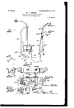
- Figure 1 is a side elevation thereof.
- Fig. 2 is a like view in its inverted position.
- Fig. 3 is a plan view of the contrivance in its Fig. l position.
- Fig. 4 is a sectional elevation thereof with certain parts removed.
- Fig. 5 is an enlarged partly sectional and partly side View showing more particularly a car or "buggy with its temporary suspending or carrying contrivance.
- Fig'. 6 is a fractional detailed view of said contrivance.
- Fig. 7 is a side view of a car or buggy.
- Fig. 8 is a plan View thereof.
- Fig. 1 is a side elevation thereof.
- Fig. 2 is a like view in its inverted position.
- Fig. 3 is a plan view of the contrivance in its Fig. l position.
- Fig. 4 is a sectional elevation thereof with certain parts removed.
- Fig. 5 is an enlarged partly sectional and partly side View showing more particularly a
- FIG. 9 is an end view of a car or buggy, showing more especially certain adjunctive parts thereof for making connection with its suspending or carrying contrivance.
- Fig. 10 is a fractional inverted view of a buggy lor car, disclosing particularly a releasing member or part adjunctive of its suspending contrivance.
- a vertical screw or shaft l being preferably screwed into said base and having immediately adjoining the latter a plane or unthreaded surface lb, upon which is slipped a freely-turning hub or sleeve Q, equipped, preferably, at its bottom edge with a beveled cogged formation 2a, with its cogs or teeth facing upward.
- a power or driving shaft 3, suitably supported or journaled in position, has fixed to one end a corresponding beveled pinion 3, meshing with said cogged formation 2a, the purpose of which is apparent.
- Fitted upon the threaded portion of the shaft or screw 1 is a hub or nut 4, having screw threaded connection therewith and adapted to ride or work up and down thereon for a purpose presently disclosed.
- Numerous bars or beams 5 are, umbrellarib-like, arranged to connect at their lower ends by pivots with a runner or ring 5, secured or screwed upon the hub 4f and also having screw-threaded connection with the shaft or screw l.
- Said ribs or beams are upheld by upper end curved braces or arms 6, having pivotal connection at their lower ends with a runner or apertured plate 7, having passing therethrough the unthreaded or plane portion of the screw or shaft l and secured or screwed upon the hub or sleeve 2, to also freely turnaround said shaft or screw.
- the braces or arms 6 have their opposite or upper curved ends pivotally connected to the beams or bars 5 about at their mid-lengths, as shown particularly by Figs. 1 and 4. Said beams or bars are stepped in their upper surfaces or edges after the fashion of producing i the pieces having attached thereto the risers and "treads of stair-steps, as will be readily understood. Said beams or bars are also suitably controlled in their individual lateral movement by articulated or jointed rods or braces 5, pivotally connected thereto, preferably as shown more especially by Fig. 1.
- a buggy or car 1.0 of general construction and suitably mounted upon the usual wheels 10 is equipped with edgewise-pre sented horizontal disks or rolls 10", arranged to project laterally therefrom, so as to bear or roll against the corresponding portions 8 of the chute sections or members 8, and thus aid to control or guide said car or buggy and steady or center it within said chute-sections in its movement along the same.
- pairs of upper end curved standards or davits 11 are produced in said socket members and receive lateral lugs or projections 11c from downward an'd inward bent or extending ⁇ terminals 11 of the standards 11, permitting a radial or endwise movement of the latter for a purpose presently indicated.
- Said suspending conti-ivances each comprises in addition to a bifurcatedarm 12 duplicate preferably platelike bars or pendants 12", hinged or pivoted at their upper ends to the lower ends of the branches of the bifurcated portion of said arm and having hinged or pivoted to their lower ends spherically or ball ended rods 12, as seen in Figs. 5, 6, and 9, the purpose of which will presently appear.
- the counterbalance or weight 12m of the standard-arm 12 is adjustable, as will be noted from Fig. 6, to adapt the same according to circumstances.
- the hinged or pivoted ball-ended rods 12 of the suspending devices 12 are adapted to be laterally engaged with slots 13 of plates 13, suitably secured to the ends of the car or buggy 10. Said plates are arranged in a lateral inclination with the slope thereof toward the chute or railway, the engagement, therefore, between said rods 12c and said slots 13 being effective from the lower edges of the inclines by the outward-swinging movement moved oppositely to provide for the ready coupling up of vthe car or buggy therewith, as will be readily seen. rlhe balls or spheres at the ends of the rods 12 are effective to prevent the end wise displacement or detachment of said rods from the slotted plates 13 of the buggy or car 10.
- first and second class levers 14 Applied to the under side of the car or buggy 10 is an arrangement of connected-together first and second class levers 14 14, respecv tively, the connection therebetween being effected by suitable means, as a rod 14; or otherwise.
- the lever 14 has a projecting cranked or angular arm 14?, equipped with a frictional roll 14M, adapted to automatically engage or contact with the upstanding lateral portion of the opposite uppermost chute-section 8 to withdraw forked or slotted retaining devices or latches 15 15, connected to the levers 14 14 from the ball-ended rods 12, the slots of the forks or retaining devices normally receiving said rods.
- the pivotal connection at 11 between the arms 12 and the standards or davits 11 permits the requisite movement of the car or buggy suspending contrivances or devices 12 in providing principally for the release or shipping of said car or 'buggy upon the chute.
- the hinged or jointed connections between the pendants 12h and the arm12, as well as the corresponding connections between said pendants and the ball-ended rods 12, allow for the requisite lateral movement necessary as the chute-sections 8, bearing the standards or davits (11, are separated and brought together in the manipulating of the chute, as in adjusting it for use.
- chute-section-carrying beams or bars 5 will be so moved through the arms or braces 6, connected to the runner 7, borne by said sleeve, as to cause said chutesections to finally assume the position indicated by Fig. 2.
- the chute-sections will be wholly inverted, so as to just reverse their normal position, droppingthe uppermost ones thereof to within a suitable distance of the surface.
- the suspending standards or davits 11, carrying the car or buggy or buggies will be thrown outward or lowered into a hori7on tal position, accordingly disposing the car or buggy or buggies some distance away from the chute,still in a suspended position,conven iently to be entered by any would-be occupants. It now being desired to restore the chute-sections, together with the various other IOO IIO
- a device of the character described comprising a number of separate chute members or sections by the assembling of which may be formed a continuous spiral chute, centering downward, and means adapted to so assemble said sections or members.
- a device of the character described comprising a number of separate chute members or sections by the assembling of which may be formed a continuous spiral chute, centering downward, means adapted to so assemble said sections, a carrying means adjunctive of said chute-sections, and means effective to conveniently dispose said carrying means to receive passengers.
- a device of the character described embracinga number of separate chute members or sections, by the assembling of which may be formed a continuous spiral chute centering downward, each such section or member having lateral upstanding portions, with a bottom portion produced upon a slight inward incline and upon a curve, and means adapted to so assemble said sections or members.
- a device of the character described embracing a number of chute sections or members, by the assembling of which may be formed a continuous spiral chute, centering downward ⁇ means adapted to so assemble said sections or members, comprising a hub, a' screw-shaft having a plane surface upon which is arranged said hub, and a second hub travcling vertically and horizontally upon said shaft, means connecting said first-noted hub and the chute-section-supporting means, and means effecting connection between said traveling hub and said chute-section-supporting means.
- a device of the character described embracing a number of chute-sections, by the assembling of which may be formed a continuous spiral chute, centering downward, a shaft carrying a vertically traveling and rotating hub, and a second rotary hub, beams or bars carrying said chute members, braces or arms, effecting connection between said beams and said hubs, respectively, and means for actuating said second hub.
- a device of the character described embracing a shaft, two hubs thereon, one having turning upon a plane surface of said shaft and the other hub having a traveling or screwthreaded connection' with said shaft, carrying means having spoke-like connections with said hubs, and means for actuating said hubs.
- Adevice of the character described comprising a number of chute members adapted to form a continuous chute or spiral incline, means for effecting the assembling of said chute members within such continuous chute, and a car or buggy suspended in position in connection with said chute, and means effective to automatically release said car or buggy for shipping or transferring it to said chute.
- a device of the character described embracing a chute, means for actuating said chute, a car or buggy, means for suspending said car or "buggy from said chute, adapted to have radial movement as the chute is actuated.
- Adevice of the character described embracing a chute, means for actuating said chute, a car or buggy, means for suspending said car or Lbuggy from said chute, comprising articulated or .pivoted arms having pendants provided with rods having end enlargements engaging lateral slots of plates secured to the ends ofsaid car or buggy, and means for the retention of said rods in said slots.
- bracing a chute means for actuating said chute, a car or buggy, means for suspending said buggy from said chute, comprising pivoted or articulated arms and adjunctive parts thereof, and means upon said car or buggy effective with said adjunctive parts to form connection between said suspending means and said buggy or car.
- a device of the character described bracing a number of chute-sections adapted to form a continuous spiral chute, centering downward, means for actuating said chutesections, and a supplemental spiral chute member suitably supported in position and effective to form a continuation of the aforesaid chute-sections.
- a device of the character described embracing a number of chute-sections, means for effecting' the assembling thereof into a continuous chute, and a supplemental spiral chute member carried upon the upper hub member ofthe operating means for the aforesaid chutesections.
- a device of the character described embracing a number of chute-sections, and means effective to invert said sections for lowering or disposing' the uppermost sections, together with the attached car or buggy for convenience in entering said buggy or car.
Landscapes
- Chutes (AREA)
Description
No. 803,473. PATENTED 00T. 31, 1905.
W. P. DAMERON. v PLEASURE RAILWAY 0R CHUTE.
APPLIGATION FILED MAILIO, 1905.
5 SHEETS-SHEET 1.
A PATENTED 00T.31,19o5. AMBRON.
ILWAY 0R CHUTE.
LED MAB.. 10, 1905.
W. P. D
PLEASURE RA APrLIoArIoN PATENTED OCT. 3l, 1905.
W. P. DAMERON. PLEASURE RAILWAY 0R CHUTE.
APPLICATION FILED MAR. l0, 1905.
5 SHEETS-SHEET 3.
WA4 @MM No. 803,473. PATENTBD OCT. 31, 1905. W. P. DAMERON. PLEASURE RAILWAY 0R CHUTE.
APPLICATION FILED MAR.10, 1905.
5 SHEETS-SHEET 4.
@noma/kom;
mmm s. am co. Pnom-umoamuenx msnmarbm u c PATBNTED OCT. 31, 1905.
W. P. DAMERON. PLEASURE RAILWAY 0R CHUTE.
APYLIGATION FILED ma 1o 1905 5 SHEETS-SHEET 5.
UNITED 'STAQIIS OFFICE.
WARREN P. DAMERON, OF SPRINGFIELD, MISSOURl, ASSIGNOR OF ONEV FOURTH TO WILLIAM H. ROSENOW, ONE-SIXTH TO PERCY HULSE, ONE- EIGHTH TO MOLLIE WATTS, AND FIVE TVVENTY-FOURTHS TO W. W- ATON, OF SPRINGFIELD, MISSOURI.
PLEASURE-RAILWAY OR CHUTE.I
Specification of Letters Patent.
Patented Oct. 31, 1905.
Application filed March 10, 1905. Serial No. 249,483.
T0 a/ZZ whom it may concern,.-
Be it known that LVVARREN P. DAMERON, a citizen of the United States,residing at Springfield, in the county of Greene and State of Missouri, have invented new and useful Improvements inPleasure-Railways or Chutes, of which the following is a specification.
My invention relates to improvements in what may be entitled pleasure-railways or chutes.
It has for its object, among other things, to afford a pleasurable and exhilarating recreation or diversion, to carry out this end in a simple and effective manner, and to promote facility and convenience in other directions.
Said invention consists of certain combinations of parts, including their arrangement, substantially as hereinafter fully disclosed, and particularly pointed out by the claims.
In the accompanying drawings, illustrating the preferred embodiment of my invention, Figure 1 is a side elevation thereof. Fig. 2 is a like view in its inverted position. Fig. 3 is a plan view of the contrivance in its Fig. l position. Fig. 4 is a sectional elevation thereof with certain parts removed. Fig. 5 is an enlarged partly sectional and partly side View showing more particularly a car or "buggy with its temporary suspending or carrying contrivance. Fig'. 6 is a fractional detailed view of said contrivance. Fig. 7 is a side view of a car or buggy. Fig. 8 is a plan View thereof. Fig. 9 is an end view of a car or buggy, showing more especially certain adjunctive parts thereof for making connection with its suspending or carrying contrivance. Fig. 10 is a fractional inverted view of a buggy lor car, disclosing particularly a releasing member or part adjunctive of its suspending contrivance.
In the disclosure of my invention I suitably arrange or support in position in or upon a base or foundation 1a a vertical screw or shaft l, being preferably screwed into said base and having immediately adjoining the latter a plane or unthreaded surface lb, upon which is slipped a freely-turning hub or sleeve Q, equipped, preferably, at its bottom edge with a beveled cogged formation 2a, with its cogs or teeth facing upward. A power or driving shaft 3, suitably supported or journaled in position, has fixed to one end a corresponding beveled pinion 3, meshing with said cogged formation 2a, the purpose of which is apparent. Fitted upon the threaded portion of the shaft or screw 1 is a hub or nut 4, having screw threaded connection therewith and adapted to ride or work up and down thereon for a purpose presently disclosed.
Numerous bars or beams 5 are, umbrellarib-like, arranged to connect at their lower ends by pivots with a runner or ring 5, secured or screwed upon the hub 4f and also having screw-threaded connection with the shaft or screw l. Said ribs or beams are upheld by upper end curved braces or arms 6, having pivotal connection at their lower ends with a runner or apertured plate 7, having passing therethrough the unthreaded or plane portion of the screw or shaft l and secured or screwed upon the hub or sleeve 2, to also freely turnaround said shaft or screw.
The braces or arms 6 have their opposite or upper curved ends pivotally connected to the beams or bars 5 about at their mid-lengths, as shown particularly by Figs. 1 and 4. Said beams or bars are stepped in their upper surfaces or edges after the fashion of producing i the pieces having attached thereto the risers and "treads of stair-steps, as will be readily understood. Said beams or bars are also suitably controlled in their individual lateral movement by articulated or jointed rods or braces 5, pivotally connected thereto, preferably as shown more especially by Fig. 1. Fitted and suitably secured to the stepped surfaces thus produced are numerous substantial pieces or sections 8, preferably of the outline disclosed, having practically horizontal surfaces or portions 8 slightly sloping or inclining, however, inward, and formed upon a curve or arc which, continued to its finality, as by the assembling of all of said members as shown, produces a downward and converging or tapering spiral conformation or chute of general funnel-like contour, the purpose of which is obvious. The lateral upstanding portions or guards 8b of the chute members serve to control or guard the car or buggy in the downward circling and spiral movement which it thus travels along said chute sections or members.
Mounted to ride up and down upon the runner or part 7, adjunctive of the hub 4, bearing the numerous chute-sections, is a sepa- IOO rate spiral chute or trunk member 9, forml of the lower ends of the parts 12 12A when ing practically a continuation of the linal or lowest one of the aforesaid chute sections or members for the delivering the car or buggy, with its occupant, into a stationary or supplemental chute member 9, with which it normally registers, as seen in Fig. 1, the latter suitably curving downward and terminating at the surface for the landing of the car or buggy and its occupants without discomfort at the desired point or end of ride. Said stationary or supplemental chute member 9 is suitably fixed and supported in position by a post or support 9", firmly planted in position and having said chute solidly secured thereto.
A buggy or car 1.0 of general construction and suitably mounted upon the usual wheels 10 is equipped with edgewise-pre sented horizontal disks or rolls 10", arranged to project laterally therefrom, so as to bear or roll against the corresponding portions 8 of the chute sections or members 8, and thus aid to control or guide said car or buggy and steady or center it within said chute-sections in its movement along the same.
Suitably positioned with relation to the normally upper or outer ends of pairs ofthe beams or bars 5, as seen particularly in Fig. are pairs of upper end curved standards or davits 11, with their lower ends telescoping and suitably held in socket members or castings 11, secured to said pairs of beams. Elongated slots 11" are produced in said socket members and receive lateral lugs or projections 11c from downward an'd inward bent or extending` terminals 11 of the standards 11, permitting a radial or endwise movement of the latter for a purpose presently indicated. Articulated or pivoted, as at 11", to the standards 11, at 0r near their upper ends, are the upper outward-curved end portions of counter-balanced bifurcated arms 12of suspendingcontrivances 12 for the car or buggy 10. Said suspending conti-ivances each comprises in addition to a bifurcatedarm 12 duplicate preferably platelike bars or pendants 12", hinged or pivoted at their upper ends to the lower ends of the branches of the bifurcated portion of said arm and having hinged or pivoted to their lower ends spherically or ball ended rods 12, as seen in Figs. 5, 6, and 9, the purpose of which will presently appear. The counterbalance or weight 12m of the standard-arm 12 is adjustable, as will be noted from Fig. 6, to adapt the same according to circumstances.
The hinged or pivoted ball-ended rods 12 of the suspending devices 12 are adapted to be laterally engaged with slots 13 of plates 13, suitably secured to the ends of the car or buggy 10. Said plates are arranged in a lateral inclination with the slope thereof toward the chute or railway, the engagement, therefore, between said rods 12c and said slots 13 being effective from the lower edges of the inclines by the outward-swinging movement moved oppositely to provide for the ready coupling up of vthe car or buggy therewith, as will be readily seen. rlhe balls or spheres at the ends of the rods 12 are effective to prevent the end wise displacement or detachment of said rods from the slotted plates 13 of the buggy or car 10.
Applied to the under side of the car or buggy 10 is an arrangement of connected-together first and second class levers 14 14, respecv tively, the connection therebetween being effected by suitable means, as a rod 14; or otherwise. The lever 14 has a projecting cranked or angular arm 14?, equipped with a frictional roll 14M, adapted to automatically engage or contact with the upstanding lateral portion of the opposite uppermost chute-section 8 to withdraw forked or slotted retaining devices or latches 15 15, connected to the levers 14 14 from the ball-ended rods 12, the slots of the forks or retaining devices normally receiving said rods. It will be noted that the pivotal connection at 11 between the arms 12 and the standards or davits 11 permits the requisite movement of the car or buggy suspending contrivances or devices 12 in providing principally for the release or shipping of said car or 'buggy upon the chute. The hinged or jointed connections between the pendants 12h and the arm12, as well as the corresponding connections between said pendants and the ball-ended rods 12, allow for the requisite lateral movement necessary as the chute-sections 8, bearing the standards or davits (11, are separated and brought together in the manipulating of the chute, as in adjusting it for use.
It will be understood, of course, that any suitable number of cars or buggies may be in like manner provided for as above described in connection with the car or buggy shown.
Assuming the chute members or sections 8 to be in the position indicated principally by Fig. 1, by suitably actuating the sleeve or part 2 2 by requisitely turning or applying power to the shaft 3 the chute-section-carrying beams or bars 5 will be so moved through the arms or braces 6, connected to the runner 7, borne by said sleeve, as to cause said chutesections to finally assume the position indicated by Fig. 2. In this movement of parts it will be seen that the chute-sections will be wholly inverted, so as to just reverse their normal position, droppingthe uppermost ones thereof to within a suitable distance of the surface. The suspending standards or davits 11, carrying the car or buggy or buggies, will be thrown outward or lowered into a hori7on tal position, accordingly disposing the car or buggy or buggies some distance away from the chute,still in a suspended position,conven iently to be entered by any would-be occupants. It now being desired to restore the chute-sections, together with the various other IOO IIO
parts, to their normal positions, power is again applied to the shaft 3, of course so as to reversely actuate or turn the latter, which movement is continued until all of said chute sections or members have been reinverted and brought close together or into intimate contact, restoring the same to normal position. In this movement of parts the car or buggy or buggies will be accordingly elevated, as seen in Fig. 1, into position to eect contact between the frictional roll-equipped lever 14 and the upstanding lateral portion of the opposite chute-section. Such contact of the parts noted will effect the automatic withdrawal of the latches or forks 15 15a from the rods 12 of the car-suspending devices 12 when the tendency of the latter to swing inward or toward the chute, under the weight applied to the upper ends of the arms l2 thereof, will automatically provide for the disengagement or release of said retaining-rodslc from the slots 13a of the plates 13 of the car. or buggy, thus permitting the shipping of the latter also automatically upon the uppermost chute-sections ready for the descent of the chute. Also it will be noted that during the latter movement of the chute-sections and adjunctive parts the centrifugal action thus imparted to the car or buggy or buggies will provide for the radial or outward displacement of the davits or standards in the slides or sockets'll, consequently permitting of the carrying of the car or buggy outward to prevent contact therebetween and the chute in effecting the aforesaid adjustment of parts.
It will be seen from the foregoing that my construction of chute, which may be readily fitted up as a railway, as also the car or buggy shown, are practically wholly unique and embody, as I believe, foundation ideas in the line of contrivances to which they severally pertain and that my claims are designed to be construed to accordingly encompass the same. Latitude, therefore, is allowed herein as to details, since they may be changed as circumstances suggest without departing from the spirit of my invention.
I claim- 1. A device of the character described, comprising a number of separate chute members or sections by the assembling of which may be formed a continuous spiral chute, centering downward, and means adapted to so assemble said sections or members.
2. A device of the character described, comprising a number of separate chute members or sections by the assembling of which may be formed a continuous spiral chute, centering downward, means adapted to so assemble said sections, a carrying means adjunctive of said chute-sections, and means effective to conveniently dispose said carrying means to receive passengers.
3. A device of the character described, embracinga number of separate chute members or sections, by the assembling of which may be formed a continuous spiral chute centering downward, each such section or member having lateral upstanding portions, with a bottom portion produced upon a slight inward incline and upon a curve, and means adapted to so assemble said sections or members.
4. A device of the character described, embracing a number of chute sections or members, by the assembling of which may be formed a continuous spiral chute, centering downward` means adapted to so assemble said sections or members, comprising a hub, a' screw-shaft having a plane surface upon which is arranged said hub, and a second hub travcling vertically and horizontally upon said shaft, means connecting said first-noted hub and the chute-section-supporting means, and means effecting connection between said traveling hub and said chute-section-supporting means.
5. A device of the character described, embracing a number of chute-sections, by the assembling of which may be formed a continuous spiral chute, centering downward, a shaft carrying a vertically traveling and rotating hub, and a second rotary hub, beams or bars carrying said chute members, braces or arms, effecting connection between said beams and said hubs, respectively, and means for actuating said second hub.
6. A device of the character described, embracing a shaft, two hubs thereon, one having turning upon a plane surface of said shaft and the other hub having a traveling or screwthreaded connection' with said shaft, carrying means having spoke-like connections with said hubs, and means for actuating said hubs.
7. Adevice of the character described, comprising a number of chute members adapted to form a continuous chute or spiral incline, means for effecting the assembling of said chute members within such continuous chute, and a car or buggy suspended in position in connection with said chute, and means effective to automatically release said car or buggy for shipping or transferring it to said chute.
8. A device of the character described, embracing a chute, means for actuating said chute, a car or buggy, means for suspending said car or "buggy from said chute, adapted to have radial movement as the chute is actuated.
9. Adevice of the character described, embracing a chute, means for actuating said chute, a car or buggy, means for suspending said car or Lbuggy from said chute, comprising articulated or .pivoted arms having pendants provided with rods having end enlargements engaging lateral slots of plates secured to the ends ofsaid car or buggy, and means for the retention of said rods in said slots.
l0. A device of the character described, em-
IOO
IIO
ISO
bracing a chute, means for actuating said chute, a car or buggy, means for suspending said buggy from said chute, comprising pivoted or articulated arms and adjunctive parts thereof, and means upon said car or buggy effective with said adjunctive parts to form connection between said suspending means and said buggy or car.
11. A device of the character described,em bracing a chute, means for actuating said chute, a car or buggy, means for suspending said buggy or car from said chute,com prising davits or standards supported upon said chute, counterbalanced bifurcated arms pivoted upon said standards or davits and having connected to the branches of their bifurcated ends hinged or pivoted pendants and said pendants having connected to their lower ends hinged or pivoted ball-ended rods, said buggy or car having laterallyslotted plates at its ends, and means also applied to said car or buggy for-.the retention of said ball-ended rods in the slots of said plates.
12. A device of the character described,em bracing a chute, means for actuating said chute, a car or buggy, means for suspending said buggy or car from said chute, means applied to the ends of said car or buggy for receiving adjunctive parts of said suspending means, and forked devices or latches also applied to said car or buggy for the effective retention of said adjunctive parts in connection with the means applied to the ends of said car or buggy.
13. A device of the character described,emf bracing a chute, means for actuating said chute, a car or buggy, means for the suspension of said car or buggy from said chute, means for effecting connection between said suspending means and said car or buggy, and an arrangement of connectedtogether first and second class levers, and latches connected to said levers and effective with the means forming connection between l l sa1d suspending means and sa1d car ori buggy for securing the latter in locked position, one of said levers adapted to be actuated by Contact with said chute for releasing said latches to permit initial movement of said car or "buggy as the latter is transferred to the chute.
14. A device of the character described,em bracing a number of chute-sections adapted to form a continuous spiral chute, centering downward, means for actuating said chutesections, and a supplemental spiral chute member suitably supported in position and effective to form a continuation of the aforesaid chute-sections.
15. A device of the character described, embracing a number of chute-sections, means for effecting' the assembling thereof into a continuous chute, and a supplemental spiral chute member carried upon the upper hub member ofthe operating means for the aforesaid chutesections.
16. A device of the character described, embracing a number of chute-sections, and means effective to invert said sections for lowering or disposing' the uppermost sections, together with the attached car or buggy for convenience in entering said buggy or car.
17. A device of the character described,em bracing anumber of invertible chute-sections, and means for effecting their inversion, as in lowering the uppermost sections, together with the attached car or buggy for convenience in entering said car or buggy, and for effecting the restoring of said sections to normal position, as in elevating said car or buggy, with its passengers or occupants, to initiate the launching of said car upon the chute for the descent of the latter.
In testimony whereof I aiiix my signature in presence of two subscribing witnesses.
WARREN P. nAMEEoN.
` Witnesses:
BENNETT S. JONES, L. S. BURKET.
Priority Applications (1)
| Application Number | Priority Date | Filing Date | Title |
|---|---|---|---|
| US24948305A US803473A (en) | 1905-03-10 | 1905-03-10 | Pleasure-railway or chute. |
Applications Claiming Priority (1)
| Application Number | Priority Date | Filing Date | Title |
|---|---|---|---|
| US24948305A US803473A (en) | 1905-03-10 | 1905-03-10 | Pleasure-railway or chute. |
Publications (1)
| Publication Number | Publication Date |
|---|---|
| US803473A true US803473A (en) | 1905-10-31 |
Family
ID=2871957
Family Applications (1)
| Application Number | Title | Priority Date | Filing Date |
|---|---|---|---|
| US24948305A Expired - Lifetime US803473A (en) | 1905-03-10 | 1905-03-10 | Pleasure-railway or chute. |
Country Status (1)
| Country | Link |
|---|---|
| US (1) | US803473A (en) |
-
1905
- 1905-03-10 US US24948305A patent/US803473A/en not_active Expired - Lifetime
Similar Documents
| Publication | Publication Date | Title |
|---|---|---|
| US803473A (en) | Pleasure-railway or chute. | |
| US1068279A (en) | Portable railway-crane. | |
| US837480A (en) | Elevated toy railway. | |
| US808183A (en) | Cable haulage and carrier-transfer. | |
| US1186966A (en) | Roundabout. | |
| US468553A (en) | Sliding hill or chute for carriages | |
| US854185A (en) | Trolley amusement. | |
| US170969A (en) | Improvement in hand-motors for street-cars | |
| US942937A (en) | Merry-go-round. | |
| US395041A (en) | Lifting-cage for mines | |
| US1107287A (en) | Amusement device. | |
| US1207914A (en) | Amusement apparatus. | |
| US758579A (en) | Swing. | |
| US436190A (en) | Hoisting apparatus | |
| US159233A (en) | Improvement in cellar-hoists or elevators | |
| US955217A (en) | Inclined railway. | |
| US439547A (en) | Crossing foe cable railways | |
| US1295145A (en) | Amusement device. | |
| US1026333A (en) | Amusement apparatus. | |
| US376700A (en) | Car-coupling | |
| US915276A (en) | Merry-go-round. | |
| US933790A (en) | Amusement device. | |
| US911191A (en) | Push-car. | |
| US95968A (en) | Improved railway moving-machine | |
| US517126A (en) | Turn-table |