US8032269B2 - Control surface failure detection for fly-by-wire aircraft - Google Patents
Control surface failure detection for fly-by-wire aircraft Download PDFInfo
- Publication number
- US8032269B2 US8032269B2 US11/947,040 US94704007A US8032269B2 US 8032269 B2 US8032269 B2 US 8032269B2 US 94704007 A US94704007 A US 94704007A US 8032269 B2 US8032269 B2 US 8032269B2
- Authority
- US
- United States
- Prior art keywords
- flight control
- control surface
- response
- recited
- cross
- Prior art date
- Legal status (The legal status is an assumption and is not a legal conclusion. Google has not performed a legal analysis and makes no representation as to the accuracy of the status listed.)
- Expired - Fee Related, expires
Links
- 238000001514 detection method Methods 0.000 title claims description 15
- RZVHIXYEVGDQDX-UHFFFAOYSA-N 9,10-anthraquinone Chemical compound C1=CC=C2C(=O)C3=CC=CC=C3C(=O)C2=C1 RZVHIXYEVGDQDX-UHFFFAOYSA-N 0.000 claims abstract description 68
- 230000004044 response Effects 0.000 claims abstract description 40
- 230000009471 action Effects 0.000 claims abstract description 22
- 230000001133 acceleration Effects 0.000 claims description 10
- 238000000034 method Methods 0.000 claims 15
- 230000008901 benefit Effects 0.000 description 4
- 238000010586 diagram Methods 0.000 description 4
- 125000004122 cyclic group Chemical group 0.000 description 3
- 230000003416 augmentation Effects 0.000 description 2
- 238000006073 displacement reaction Methods 0.000 description 2
- 230000006870 function Effects 0.000 description 2
- 238000012986 modification Methods 0.000 description 2
- 230000004048 modification Effects 0.000 description 2
- 230000006399 behavior Effects 0.000 description 1
- 230000008859 change Effects 0.000 description 1
- 238000006243 chemical reaction Methods 0.000 description 1
- 238000013329 compounding Methods 0.000 description 1
- 150000001875 compounds Chemical class 0.000 description 1
- 230000003750 conditioning effect Effects 0.000 description 1
- 238000011161 development Methods 0.000 description 1
- 230000009977 dual effect Effects 0.000 description 1
- 230000002452 interceptive effect Effects 0.000 description 1
- 230000003287 optical effect Effects 0.000 description 1
- 238000012545 processing Methods 0.000 description 1
- 238000011160 research Methods 0.000 description 1
- 230000000153 supplemental effect Effects 0.000 description 1
- 238000009966 trimming Methods 0.000 description 1
Images


Classifications
-
- B—PERFORMING OPERATIONS; TRANSPORTING
- B64—AIRCRAFT; AVIATION; COSMONAUTICS
- B64C—AEROPLANES; HELICOPTERS
- B64C27/00—Rotorcraft; Rotors peculiar thereto
- B64C27/006—Safety devices
Definitions
- the present invention relates to a fly-by-wire flight control system.
- Some fly-by-wire aircraft utilize highly optimized model-following control systems as well as sophisticated electronic mixing. These systems rely on having a correct, real-time mathematical representation of the aircraft available in the flight control system. Small model variations can be accounted for but large variations, such as loss of tail rotor of a rotary-wing aircraft, produce large discrepancies between the flight control system model and the resulting aircraft dynamics. These discrepancies tend to cause difficulties in control of the aircraft after such failures.
- Rotary-wing aircraft are typically highly cross coupled and may include a canted tail rotor such that the control mixing algorithm requires the yaw term to feed both pitch and roll axes with a relatively high gain to compensate for the canted tail rotor.
- the aircraft starts to spin and the flight control system responds through application of full yaw input opposite the spin.
- This typically causes the control mixing algorithm to also apply pitch and roll to compensate for the yaw input, which then results in a relatively large pitch and roll motion of the aircraft since the yaw input did not produce the expected pitch and roll motion response.
- Such disturbances may further complicate an already difficult loss of tail-rotor event by compounding the yaw motion with pitch and roll motion.
- tail rotor needs minimal anti-torque produced thrust. As such, tail rotor failure will not cause a significant change in aircraft behavior unless the conventional fly-by-wire system unintentionally complicates such a disturbance.
- a flight control system includes a module which detects a failure of a flight control surface in response to a frequency sweep of the flight control surface and performs at least one action in response to the detected failure.
- a failure detection method for a flight control surface of a fly-by-wire aircraft includes performing a frequency sweep of a flight control surface to cause an acceleration response and a rate response of the flight control surface; computing a cross-correlation using at least the acceleration response and the rate response; detecting a failure of the flight control surface using at least the information from the computed cross-correlation; and performing at least one action in response to the detected fail.
- FIG. 1 is a general perspective view of an exemplary rotary wing aircraft for use with the present invention
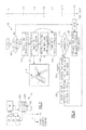
- FIG. 2 is a schematic diagram of a model following flight control system
- FIG. 3 is a block diagram of a module which implements a flight control surface failure detection algorithm
- FIG. 4 is a block diagram of a flight control surface failure detection algorithm.
- FIG. 1 illustrates a general perspective view of an exemplary vertical takeoff and landing (VTOL) rotary-wing aircraft 10 for use with the present invention.
- the rotary-wing aircraft 10 includes a main rotor assembly 12 and tail rotor assembly 14 .
- VTOL vertical takeoff and landing
- the rotary-wing aircraft 10 includes a main rotor assembly 12 and tail rotor assembly 14 .
- a particular helicopter configuration is illustrated and described in disclosed embodiments, other configurations and/or machines, such as high speed compound rotary-wing aircraft with supplemental translational thrust systems, dual contra-rotating, coaxial rotor system aircraft, turbo-props, tilt-rotors, tilt-wing aircraft, and fixed-wing aircraft will also benefit from embodiments of the present invention.
- a fly-by-wire type flight control system 16 includes a model following control system which shapes the pilot's controller and displacement commands through an inverse vehicle model to produce the desired aircraft response.
- the system 16 includes a Primary Flight Control System (PFCS) 22 and an Automatic Flight Augmentation and Cuing System (FACS) 24 .
- PFCS Primary Flight Control System
- FACS Automatic Flight Augmentation and Cuing System
- the PFCS 22 is the flight critical portion of the flight control system, while the FACS 24 is the mission critical portion.
- the FACS 24 augments the performance of the PFCS 22 .
- the PFCS 22 and FACS 24 execute explicit model following control laws to provide both control and stability augmentation. In this control law architecture, pilot commands are shaped directly into desired aircraft responses. These desired commands are then passed through an inverse aircraft model to obtain the control commands required to produce the desired response. The difference between the desired command and the aircraft response is also fed back to drive these errors towards zero, thus improving the model following performance.
- the PFCS 22 and FACS 24 each receive the force output command signals of a collective controller 18 on line 20 , a cyclic controller 28 on line 30 , and the aircraft's sensed parameter signals from sensors 32 , on lines 34 .
- the collective controller 18 and the cyclic controller 28 may take various forms including sidearm controllers, a yaw pedal system or other such flight controllers.
- the pilot command signals on lines 20 , 30 and the sensed parameter signals on lines 34 are shown consolidated within trunk lines 32 and 34 in the PFCS and FACS, respectively.
- the PFCS 22 and FACS 24 may each contain separate control channel logic laws for controlling the yaw, pitch, roll and lift axes of the aircraft.
- the logic is included in the PFCS and FACS control modules (schematically represented by blocks 35 - 38 for the PFCS and blocks 39 - 42 for the FACS).
- the sensed parameter signals from aircraft sensors 32 on lines 34 , provide the PFCS and FACS with the aircraft's angular rate and attitude response to the rotor command signals.
- the PFCS logic provides rotor command signals and the FACS logic provides conditioning and/or trimming of the PFCS four axis logic functions.
- the PFCS and FACS logic modules interconnect through bus 44 to provide rotor command signals on output lines 46 to a mixing function 48 which communicates commands on lines 58 for the displacement of servos 50 and linkages 52 to control the tip path plane of the main rotor 12 .
- a mixed command signal is also provided on line 58 to the tail rotor servos 54 which control the thrust of the tail rotor 14 through linkages 56 .
- a module 62 which performs a flight control surface failure detection algorithm 60 (see also FIG. 4 ) is schematically illustrated in a block diagram format.
- the algorithm 60 is the scheme by which the decisions are made in the disclosed non-limiting embodiments.
- the module 62 utilizes, in an exemplary embodiment, the model-following architecture of the flight control system 16 to implement the flight control failure detection algorithm 60 .
- the flight control failure detection algorithm 60 may be microprocessor based.
- the module 62 includes a controller 64 , which may be a flight computer, a portion of a central vehicle main control system, an interactive vehicle dynamics module, stand-alone controllers typically implemented as a line-replaceable unit (LRU).
- the controller 64 typically includes a processor 64 A, a memory 64 B, and an interface 64 C for communicating with the flight control system 16 , the collective controller 18 , the cyclic controller 28 the sensors 32 , and other avionics systems.
- the memory 64 B may, for example only, include RAM, ROM, DVD, CD, a hard drive, or other electronic, optical, magnetic, or any other computer readable medium onto which is stored the data and control algorithms described herein.
- the flight control surface failure detection algorithm 60 readily detects the loss of tail rotor thrust and reconfigures the fly-by-wire flight control system 16
- the flight control surface failure detection algorithm 60 allows the fly-by-wire system 16 to detect and mitigate flight control failures.
- the flight control surface failure detection algorithm 60 monitors model-following performance of a flight control surface such as the tail rotor 14 . It should be understood that although a tail rotor is disclosed in the illustrated non-limiting embodiment, any aircraft flight control surface may be so monitored.
- a pending tail rotor failure is declared.
- all yaw cross-axis mixing inputs are disabled (action 102 ). This prevents an immediate aircraft response due to yaw/pitch and yaw/roll mixing terms should the tail rotor actually be disabled.
- the tail rotor is considered operable when the tail rotor will respond at least partially to inputs. ⁇ Modify that sentence appropriately. This attempts to define “operable” as a partial response to any input. ⁇
- the next task for the flight control surface failure detection algorithm 60 is to determine if a tail rotor failure actually exists. This is achieved by application of a very small frequency sweep to the tail rotor 14 through the tail rotor servos 54 (action 104 ) the frequency sweep may be a sine wave input to the tail rotor 14 in which the frequency thereof varies with time, such as two (2) Hertz (Hz) to four (4) Hz over a duration of two (2) seconds—also often referred to as a “chirp”.
- Hz Hertz
- chirp also often referred to as a “chirp”.
- the frequency sweep is of very small amplitude such that pilots may not even perceive the yaw response but provides enough input to cause yaw acceleration and yaw rate detectable by the flight control surface failure detection algorithm 60 to reflect the sweep (if the tail rotor is still providing thrust).
- the flight control surface failure detection algorithm 60 records these parameters (e.g., yaw acceleration and yaw rate) as the sweep is being applied (action 106 ). After completion of the sweep, a cross-correlation is computed between the sweep (e.g., the input and known signal) and the recorded yaw rate and yaw acceleration (e.g., the output and determined signal) (action 108 ). In signal processing, cross-correlation (or sometimes “cross-covariance”) is a measure of similarity of two signals, commonly used to find features in an unknown signal by comparing the unknown signal to a known one. The cross-correlation is then determined to be either “high” or “low” through comparison to some value (action 110 ).
- these parameters e.g., yaw acceleration and yaw rate
- a cross-correlation is computed between the sweep (e.g., the input and known signal) and the recorded yaw rate and yaw acceleration (e.g., the output
- the aircraft responded to the sweep and no tail rotor failure exists such that all yaw cross-axis mixing terms are again enabled (action 200 ).
- a tail rotor failure exists such that all yaw mixing to other axes is disabled, the yaw channel is put into direct mode (action 300 ) and a caution message is displayed (action 302 ). Disabling all yaw mixing to other axes and placing the yaw channel into direct mode facilitates autorotation entry and alerts the aircrew well before they may otherwise be capable of reaction to a tail rotor failure. It is noted that the times shown on FIG. 3 are merely exemplary.
- This algorithm can also be applied to other control surfaces on rotorcraft and fixed-wing aircraft to detect and mitigate control surface failures.
- This algorithm can be applied to a broad range of aircraft—its immediate use is on rotorcraft that have highly coupled tail rotor systems.
Landscapes
- Engineering & Computer Science (AREA)
- Mechanical Engineering (AREA)
- Aviation & Aerospace Engineering (AREA)
- Control Of Position, Course, Altitude, Or Attitude Of Moving Bodies (AREA)
- Traffic Control Systems (AREA)
Priority Applications (2)
| Application Number | Priority Date | Filing Date | Title |
|---|---|---|---|
| US11/947,040 US8032269B2 (en) | 2007-05-18 | 2007-11-29 | Control surface failure detection for fly-by-wire aircraft |
| TW097118233A TWI357392B (en) | 2007-05-18 | 2008-05-16 | Control surface failure detection for fly-by-wire |
Applications Claiming Priority (2)
| Application Number | Priority Date | Filing Date | Title |
|---|---|---|---|
| US93877007P | 2007-05-18 | 2007-05-18 | |
| US11/947,040 US8032269B2 (en) | 2007-05-18 | 2007-11-29 | Control surface failure detection for fly-by-wire aircraft |
Publications (2)
| Publication Number | Publication Date |
|---|---|
| US20090012658A1 US20090012658A1 (en) | 2009-01-08 |
| US8032269B2 true US8032269B2 (en) | 2011-10-04 |
Family
ID=40156885
Family Applications (1)
| Application Number | Title | Priority Date | Filing Date |
|---|---|---|---|
| US11/947,040 Expired - Fee Related US8032269B2 (en) | 2007-05-18 | 2007-11-29 | Control surface failure detection for fly-by-wire aircraft |
Country Status (4)
| Country | Link |
|---|---|
| US (1) | US8032269B2 (de) |
| EP (1) | EP2160322B1 (de) |
| TW (1) | TWI357392B (de) |
| WO (1) | WO2008156926A2 (de) |
Cited By (4)
| Publication number | Priority date | Publication date | Assignee | Title |
|---|---|---|---|---|
| US20110057071A1 (en) * | 2009-09-10 | 2011-03-10 | Vineet Sahasrabudhe | Life improving flight control system |
| US20150001337A1 (en) * | 2013-07-01 | 2015-01-01 | Bell Helicopter Textron Inc. | Independent Hydraulic Control System for Rotorcraft Secondary Rotor |
| US9499283B1 (en) * | 2015-06-15 | 2016-11-22 | The United States Of America As Represented By The Secretary Of The Navy | Freeplay measurement device |
| US11840351B2 (en) | 2021-04-05 | 2023-12-12 | Beta Air, Llc | Aircraft for self-neutralizing flight |
Families Citing this family (11)
| Publication number | Priority date | Publication date | Assignee | Title |
|---|---|---|---|---|
| DE202009001355U1 (de) | 2009-02-04 | 2009-05-20 | RÖHR, Ulrich | Modellflugkörpersteuer- und Empfangseinrichtung |
| US20130038525A1 (en) * | 2010-02-12 | 2013-02-14 | Jan Håkegård | Vehicular display system and a method for controlling the display system |
| DE102012003910A1 (de) | 2011-04-15 | 2012-10-18 | Ulrich Röhr | System zur drahtlosen Steuerung eines RC-Modells, Sendeeinrichtung, Empfangseinrichtung sowie Verfahren |
| US9102400B2 (en) | 2011-10-21 | 2015-08-11 | Sikorsky Aircraft Corporation | Methods and systems for providing constant-feel, multi-axis tactile cues |
| US8718841B2 (en) | 2012-02-14 | 2014-05-06 | Sikorsky Aircraft Corporation | Method and system for providing sideslip envelope protection |
| EP2940547B1 (de) * | 2014-05-01 | 2019-03-06 | Sikorsky Aircraft Corporation | Mischen für koaxialen rotor bei niedriger geschwindigkeit |
| US10124889B2 (en) * | 2015-05-06 | 2018-11-13 | Sikorsky Aircraft Corporation | Tail rotor failure recovery controller |
| US20170233104A1 (en) * | 2016-02-12 | 2017-08-17 | Ge Aviation Systems Llc | Real Time Non-Onboard Diagnostics of Aircraft Failures |
| US10359785B2 (en) * | 2016-03-31 | 2019-07-23 | Sikorsky Aircraft Corporation | Touchdown orientation control system for a rotary wing aircraft and method |
| US10604236B2 (en) | 2016-06-01 | 2020-03-31 | Regents Of The University Of Minnesota | Fault-tolerant aircraft flight control using a subset of aerodynamic control surfaces |
| WO2019023322A1 (en) * | 2017-07-27 | 2019-01-31 | SkyRyse, Inc. | SYSTEM AND METHOD FOR SITUATION APPRAISAL, VEHICLE CONTROL AND / OR IMPREVUS PLANNING |
Citations (26)
| Publication number | Priority date | Publication date | Assignee | Title |
|---|---|---|---|---|
| US2713156A (en) * | 1953-12-23 | 1955-07-12 | Louis S Guarino | Rotor tip path plane indicator for helicopter |
| US3407399A (en) * | 1965-06-21 | 1968-10-22 | Bell Aerospace Corp | Helicopter warning system |
| US3502967A (en) * | 1968-05-27 | 1970-03-24 | Iit Res Inst | System for detecting twist and bend in turbine blades |
| US3938762A (en) | 1974-05-20 | 1976-02-17 | Textron, Inc. | Rotor blade force track sensing system and automatic span tracking system |
| US4053123A (en) | 1976-04-16 | 1977-10-11 | Chadwick-Helmuth Company, Inc. | Method and apparatus to determine need for rotor blade pitch adjustment and/or blade substitution |
| US4345237A (en) * | 1979-09-12 | 1982-08-17 | Verenigte Flugtechnische Werke Gmbh | Supervisory and monitoring system for helicopter propeller blades |
| US4420808A (en) | 1980-04-01 | 1983-12-13 | United Technologies Corporation | Multi-axis force stick, self-trimmed aircraft flight control system |
| US4528564A (en) | 1982-07-30 | 1985-07-09 | Ulrich Trampnau | Warning device for helicopters |
| US4529155A (en) | 1983-12-09 | 1985-07-16 | United Technologies Corporation | Redundant tail rotor control system |
| US4540141A (en) | 1983-09-22 | 1985-09-10 | United Technologies Corporation | Fail-safe tail rotor control system |
| US4648568A (en) | 1985-05-28 | 1987-03-10 | Phillips Richard G | Emergency anti-torque control system and method for helicopters |
| US4759514A (en) | 1986-09-30 | 1988-07-26 | The Boeing Company | Tail rotor yaw position control for a helicopter |
| US4934825A (en) | 1987-12-22 | 1990-06-19 | United Technologies Corporation | Propeller phase control apparatus |
| US5214973A (en) | 1992-01-15 | 1993-06-01 | Hambric Lori H | Traction drive power transmission systems |
| US5327358A (en) * | 1991-08-07 | 1994-07-05 | The Texas A&M University System | Apparatus and method for damage detection |
| US5483833A (en) * | 1994-03-22 | 1996-01-16 | Martin Marietta Energy Systems, Inc. | Method and apparatus for monitoring aircraft components |
| US5607122A (en) | 1994-12-22 | 1997-03-04 | Bell Helicopter Textron Inc. | Tail rotor authority control for a helicopter |
| US5715162A (en) * | 1992-10-13 | 1998-02-03 | United Technologies Corporation | Correlative filter for a synchrophaser |
| US5749540A (en) | 1996-07-26 | 1998-05-12 | Arlton; Paul E. | System for controlling and automatically stabilizing the rotational motion of a rotary wing aircraft |
| US5806805A (en) * | 1996-08-07 | 1998-09-15 | The Boeing Company | Fault tolerant actuation system for flight control actuators |
| US5931681A (en) | 1996-07-23 | 1999-08-03 | Eurocopter | Device for connection between two cables, one of which is able to move translationally and/or rotationally with respect to the other |
| US6036141A (en) | 1995-10-12 | 2000-03-14 | Mcdonnell Douglas Corporation | Jet thruster for helicopter antitorque and yaw control system |
| US6446015B1 (en) * | 2000-02-23 | 2002-09-03 | The United States Of America As Represented By The Administrator Of The National Aeronautics And Space Administration | Method and apparatus for flight data acquisition using an optimized multiple frequency waveform |
| US6929215B2 (en) | 2001-09-04 | 2005-08-16 | Paul E. Arlton | Rotor system for helicopters |
| US20070124038A1 (en) * | 2005-11-28 | 2007-05-31 | Airbus France | Method and device for detecting oscillatory failures in a position servocontrol subsystem of an aircraft control surface |
| US20070173988A1 (en) * | 2006-01-24 | 2007-07-26 | Pitt Dale M | System for and method of monitoring free play of aircraft control surfaces |
-
2007
- 2007-11-29 US US11/947,040 patent/US8032269B2/en not_active Expired - Fee Related
-
2008
- 2008-05-07 EP EP08825924.7A patent/EP2160322B1/de active Active
- 2008-05-07 WO PCT/US2008/062831 patent/WO2008156926A2/en active Application Filing
- 2008-05-16 TW TW097118233A patent/TWI357392B/zh not_active IP Right Cessation
Patent Citations (27)
| Publication number | Priority date | Publication date | Assignee | Title |
|---|---|---|---|---|
| US2713156A (en) * | 1953-12-23 | 1955-07-12 | Louis S Guarino | Rotor tip path plane indicator for helicopter |
| US3407399A (en) * | 1965-06-21 | 1968-10-22 | Bell Aerospace Corp | Helicopter warning system |
| US3502967A (en) * | 1968-05-27 | 1970-03-24 | Iit Res Inst | System for detecting twist and bend in turbine blades |
| US3938762A (en) | 1974-05-20 | 1976-02-17 | Textron, Inc. | Rotor blade force track sensing system and automatic span tracking system |
| US4053123A (en) | 1976-04-16 | 1977-10-11 | Chadwick-Helmuth Company, Inc. | Method and apparatus to determine need for rotor blade pitch adjustment and/or blade substitution |
| US4345237A (en) * | 1979-09-12 | 1982-08-17 | Verenigte Flugtechnische Werke Gmbh | Supervisory and monitoring system for helicopter propeller blades |
| US4420808A (en) | 1980-04-01 | 1983-12-13 | United Technologies Corporation | Multi-axis force stick, self-trimmed aircraft flight control system |
| US4528564A (en) | 1982-07-30 | 1985-07-09 | Ulrich Trampnau | Warning device for helicopters |
| US4540141A (en) | 1983-09-22 | 1985-09-10 | United Technologies Corporation | Fail-safe tail rotor control system |
| US4529155A (en) | 1983-12-09 | 1985-07-16 | United Technologies Corporation | Redundant tail rotor control system |
| US4648568A (en) | 1985-05-28 | 1987-03-10 | Phillips Richard G | Emergency anti-torque control system and method for helicopters |
| US4759514A (en) | 1986-09-30 | 1988-07-26 | The Boeing Company | Tail rotor yaw position control for a helicopter |
| US4934825A (en) | 1987-12-22 | 1990-06-19 | United Technologies Corporation | Propeller phase control apparatus |
| US5327358A (en) * | 1991-08-07 | 1994-07-05 | The Texas A&M University System | Apparatus and method for damage detection |
| US5214973A (en) | 1992-01-15 | 1993-06-01 | Hambric Lori H | Traction drive power transmission systems |
| US5715162A (en) * | 1992-10-13 | 1998-02-03 | United Technologies Corporation | Correlative filter for a synchrophaser |
| US5483833A (en) * | 1994-03-22 | 1996-01-16 | Martin Marietta Energy Systems, Inc. | Method and apparatus for monitoring aircraft components |
| US5607122A (en) | 1994-12-22 | 1997-03-04 | Bell Helicopter Textron Inc. | Tail rotor authority control for a helicopter |
| US6036141A (en) | 1995-10-12 | 2000-03-14 | Mcdonnell Douglas Corporation | Jet thruster for helicopter antitorque and yaw control system |
| US5931681A (en) | 1996-07-23 | 1999-08-03 | Eurocopter | Device for connection between two cables, one of which is able to move translationally and/or rotationally with respect to the other |
| US5749540A (en) | 1996-07-26 | 1998-05-12 | Arlton; Paul E. | System for controlling and automatically stabilizing the rotational motion of a rotary wing aircraft |
| US5806805A (en) * | 1996-08-07 | 1998-09-15 | The Boeing Company | Fault tolerant actuation system for flight control actuators |
| US6446015B1 (en) * | 2000-02-23 | 2002-09-03 | The United States Of America As Represented By The Administrator Of The National Aeronautics And Space Administration | Method and apparatus for flight data acquisition using an optimized multiple frequency waveform |
| US6929215B2 (en) | 2001-09-04 | 2005-08-16 | Paul E. Arlton | Rotor system for helicopters |
| US20070124038A1 (en) * | 2005-11-28 | 2007-05-31 | Airbus France | Method and device for detecting oscillatory failures in a position servocontrol subsystem of an aircraft control surface |
| US20070173988A1 (en) * | 2006-01-24 | 2007-07-26 | Pitt Dale M | System for and method of monitoring free play of aircraft control surfaces |
| US7933691B2 (en) * | 2006-01-24 | 2011-04-26 | The Boeing Company | System for and method of monitoring free play of aircraft control surfaces |
Non-Patent Citations (1)
| Title |
|---|
| International Search Report for International Application No. PCT/US2008/062831 dated Jun. 17, 2009. |
Cited By (7)
| Publication number | Priority date | Publication date | Assignee | Title |
|---|---|---|---|---|
| US20110057071A1 (en) * | 2009-09-10 | 2011-03-10 | Vineet Sahasrabudhe | Life improving flight control system |
| US9102399B2 (en) * | 2009-09-10 | 2015-08-11 | Sikorsky Aircraft Corporation | Life improving flight control system |
| US20150001337A1 (en) * | 2013-07-01 | 2015-01-01 | Bell Helicopter Textron Inc. | Independent Hydraulic Control System for Rotorcraft Secondary Rotor |
| EP2821343A1 (de) * | 2013-07-01 | 2015-01-07 | Bell Helicopter Textron Inc. | Unabhängiges hydraulisches Steuerungssystem für Sekundärrotor eines Drehflügelflugzeugs |
| US9815553B2 (en) * | 2013-07-01 | 2017-11-14 | Bell Helicopter Tectron Inc. | Independent hydraulic control system for rotorcraft secondary rotor |
| US9499283B1 (en) * | 2015-06-15 | 2016-11-22 | The United States Of America As Represented By The Secretary Of The Navy | Freeplay measurement device |
| US11840351B2 (en) | 2021-04-05 | 2023-12-12 | Beta Air, Llc | Aircraft for self-neutralizing flight |
Also Published As
| Publication number | Publication date |
|---|---|
| US20090012658A1 (en) | 2009-01-08 |
| WO2008156926A3 (en) | 2009-08-06 |
| WO2008156926A2 (en) | 2008-12-24 |
| EP2160322B1 (de) | 2016-04-13 |
| EP2160322A2 (de) | 2010-03-10 |
| EP2160322A4 (de) | 2013-08-14 |
| WO2008156926A8 (en) | 2010-02-25 |
| TWI357392B (en) | 2012-02-01 |
| TW200909303A (en) | 2009-03-01 |
Similar Documents
| Publication | Publication Date | Title |
|---|---|---|
| US8032269B2 (en) | Control surface failure detection for fly-by-wire aircraft | |
| US8855837B2 (en) | Altitude and acceleration command altitude hold algorithm for rotorcraft with large center of gravity range | |
| US10843796B2 (en) | Rotorcraft advanced autopilot control arrangement and methods | |
| US9377784B2 (en) | Adaptable automatic nacelle conversion for tilt rotor aircraft | |
| CN109240073B (zh) | 具有使用状态比较的冗余处理器的旋转飞行器 | |
| US8231085B2 (en) | Automatic trim system for fly-by-wire aircraft with unique trim controllers | |
| US7931231B2 (en) | Engine anticipation for rotary-wing aircraft | |
| US10124889B2 (en) | Tail rotor failure recovery controller | |
| US20200070966A1 (en) | Stuck in Detent Monitors for Collective and Cyclic Sticks | |
| US20180222573A1 (en) | System and method for stabilizing longitudinal acceleration of a rotorcraft | |
| US8825233B2 (en) | Synthetic estimation of rotorcraft airspeed | |
| US10351230B2 (en) | Initial rotor state compensation for a rotorcraft | |
| US10279893B2 (en) | System and method for validating rotorcraft position coordinates | |
| EP3578458B1 (de) | System und verfahren zur höhensteuerung eines drehflüglers | |
| US11685523B2 (en) | System and method for monitoring aircraft pilot control position and providing a retrim prompt | |
| US8718841B2 (en) | Method and system for providing sideslip envelope protection | |
| CN110658843A (zh) | 用于确定旋翼飞行器的速度的系统和方法 | |
| EP3613671B1 (de) | Glättung einer drehflüglersteuerungsübergang | |
| US10214298B2 (en) | Station deselect and cueing system |
Legal Events
| Date | Code | Title | Description |
|---|---|---|---|
| AS | Assignment |
Owner name: SIKORSKY AIRCRAFT CORPORATION, CONNECTICUT Free format text: ASSIGNMENT OF ASSIGNORS INTEREST;ASSIGNORS:CHEREPINSKY, IGOR;DRISCOLL, JOSEPH T.;KINKEAD, WILLIAM DOUGLAS;AND OTHERS;REEL/FRAME:020175/0151 Effective date: 20071126 |
|
| ZAAA | Notice of allowance and fees due |
Free format text: ORIGINAL CODE: NOA |
|
| ZAAB | Notice of allowance mailed |
Free format text: ORIGINAL CODE: MN/=. |
|
| STCF | Information on status: patent grant |
Free format text: PATENTED CASE |
|
| FPAY | Fee payment |
Year of fee payment: 4 |
|
| MAFP | Maintenance fee payment |
Free format text: PAYMENT OF MAINTENANCE FEE, 8TH YEAR, LARGE ENTITY (ORIGINAL EVENT CODE: M1552); ENTITY STATUS OF PATENT OWNER: LARGE ENTITY Year of fee payment: 8 |
|
| FEPP | Fee payment procedure |
Free format text: MAINTENANCE FEE REMINDER MAILED (ORIGINAL EVENT CODE: REM.); ENTITY STATUS OF PATENT OWNER: LARGE ENTITY |
|
| LAPS | Lapse for failure to pay maintenance fees |
Free format text: PATENT EXPIRED FOR FAILURE TO PAY MAINTENANCE FEES (ORIGINAL EVENT CODE: EXP.); ENTITY STATUS OF PATENT OWNER: LARGE ENTITY |
|
| STCH | Information on status: patent discontinuation |
Free format text: PATENT EXPIRED DUE TO NONPAYMENT OF MAINTENANCE FEES UNDER 37 CFR 1.362 |
|
| FP | Lapsed due to failure to pay maintenance fee |
Effective date: 20231004 |