US8027608B2 - Fixing device, image forming apparatus equipped therewith, and recording medium on which temperature control program is recorded - Google Patents
Fixing device, image forming apparatus equipped therewith, and recording medium on which temperature control program is recorded Download PDFInfo
- Publication number
- US8027608B2 US8027608B2 US12/546,926 US54692609A US8027608B2 US 8027608 B2 US8027608 B2 US 8027608B2 US 54692609 A US54692609 A US 54692609A US 8027608 B2 US8027608 B2 US 8027608B2
- Authority
- US
- United States
- Prior art keywords
- temperature
- section
- heating
- fixing device
- heating section
- Prior art date
- Legal status (The legal status is an assumption and is not a legal conclusion. Google has not performed a legal analysis and makes no representation as to the accuracy of the status listed.)
- Expired - Fee Related, expires
Links
- 238000010438 heat treatment Methods 0.000 claims abstract description 263
- 229910052751 metal Inorganic materials 0.000 claims description 46
- 239000002184 metal Substances 0.000 claims description 46
- 239000010410 layer Substances 0.000 claims description 40
- 239000000463 material Substances 0.000 claims description 39
- 239000002344 surface layer Substances 0.000 claims description 10
- 230000002093 peripheral effect Effects 0.000 claims description 4
- 229910052736 halogen Inorganic materials 0.000 abstract description 40
- 150000002367 halogens Chemical class 0.000 abstract description 40
- 238000012546 transfer Methods 0.000 description 72
- 108091008695 photoreceptors Proteins 0.000 description 44
- 239000011347 resin Substances 0.000 description 29
- 229920005989 resin Polymers 0.000 description 29
- 238000000034 method Methods 0.000 description 24
- 239000000049 pigment Substances 0.000 description 18
- 239000011230 binding agent Substances 0.000 description 14
- 239000003086 colorant Substances 0.000 description 14
- 239000002245 particle Substances 0.000 description 13
- -1 polyethylene Polymers 0.000 description 12
- 239000003795 chemical substances by application Substances 0.000 description 10
- 229920000728 polyester Polymers 0.000 description 9
- YCKRFDGAMUMZLT-UHFFFAOYSA-N Fluorine atom Chemical compound [F] YCKRFDGAMUMZLT-UHFFFAOYSA-N 0.000 description 8
- 238000010586 diagram Methods 0.000 description 8
- 229920001971 elastomer Polymers 0.000 description 8
- 239000011737 fluorine Substances 0.000 description 8
- 229910052731 fluorine Inorganic materials 0.000 description 8
- 230000008569 process Effects 0.000 description 8
- 239000001993 wax Substances 0.000 description 8
- XEEYBQQBJWHFJM-UHFFFAOYSA-N Iron Chemical compound [Fe] XEEYBQQBJWHFJM-UHFFFAOYSA-N 0.000 description 6
- PPBRXRYQALVLMV-UHFFFAOYSA-N Styrene Chemical compound C=CC1=CC=CC=C1 PPBRXRYQALVLMV-UHFFFAOYSA-N 0.000 description 6
- XAGFODPZIPBFFR-UHFFFAOYSA-N aluminium Chemical compound [Al] XAGFODPZIPBFFR-UHFFFAOYSA-N 0.000 description 6
- 238000004891 communication Methods 0.000 description 6
- 230000007423 decrease Effects 0.000 description 6
- 230000009477 glass transition Effects 0.000 description 6
- 229920001343 polytetrafluoroethylene Polymers 0.000 description 6
- 239000004810 polytetrafluoroethylene Substances 0.000 description 6
- OKTJSMMVPCPJKN-UHFFFAOYSA-N Carbon Chemical compound [C] OKTJSMMVPCPJKN-UHFFFAOYSA-N 0.000 description 5
- 229910052782 aluminium Inorganic materials 0.000 description 5
- 230000006866 deterioration Effects 0.000 description 5
- 238000011161 development Methods 0.000 description 5
- 239000006249 magnetic particle Substances 0.000 description 5
- 230000003287 optical effect Effects 0.000 description 5
- 229920002943 EPDM rubber Polymers 0.000 description 4
- 239000004698 Polyethylene Substances 0.000 description 4
- 230000015572 biosynthetic process Effects 0.000 description 4
- 239000004020 conductor Substances 0.000 description 4
- 230000006870 function Effects 0.000 description 4
- 230000005415 magnetization Effects 0.000 description 4
- 229920000573 polyethylene Polymers 0.000 description 4
- 238000007639 printing Methods 0.000 description 4
- 239000000126 substance Substances 0.000 description 4
- 239000000758 substrate Substances 0.000 description 4
- 239000004743 Polypropylene Substances 0.000 description 3
- 230000005540 biological transmission Effects 0.000 description 3
- 239000006229 carbon black Substances 0.000 description 3
- 230000000052 comparative effect Effects 0.000 description 3
- 229920001577 copolymer Polymers 0.000 description 3
- 230000003247 decreasing effect Effects 0.000 description 3
- 239000006185 dispersion Substances 0.000 description 3
- 239000006260 foam Substances 0.000 description 3
- 229910052742 iron Inorganic materials 0.000 description 3
- 230000007246 mechanism Effects 0.000 description 3
- 229920001155 polypropylene Polymers 0.000 description 3
- 238000010298 pulverizing process Methods 0.000 description 3
- 229920002379 silicone rubber Polymers 0.000 description 3
- 239000004945 silicone rubber Substances 0.000 description 3
- 229920003002 synthetic resin Polymers 0.000 description 3
- JOYRKODLDBILNP-UHFFFAOYSA-N Ethyl urethane Chemical compound CCOC(N)=O JOYRKODLDBILNP-UHFFFAOYSA-N 0.000 description 2
- PXHVJJICTQNCMI-UHFFFAOYSA-N Nickel Chemical compound [Ni] PXHVJJICTQNCMI-UHFFFAOYSA-N 0.000 description 2
- 230000015271 coagulation Effects 0.000 description 2
- 238000005345 coagulation Methods 0.000 description 2
- 230000000694 effects Effects 0.000 description 2
- 238000004945 emulsification Methods 0.000 description 2
- 239000010408 film Substances 0.000 description 2
- 229920001973 fluoroelastomer Polymers 0.000 description 2
- 230000004907 flux Effects 0.000 description 2
- 239000000178 monomer Substances 0.000 description 2
- 229920001721 polyimide Polymers 0.000 description 2
- 239000000843 powder Substances 0.000 description 2
- 238000012545 processing Methods 0.000 description 2
- 239000004065 semiconductor Substances 0.000 description 2
- 239000010935 stainless steel Substances 0.000 description 2
- 229910001220 stainless steel Inorganic materials 0.000 description 2
- 238000010558 suspension polymerization method Methods 0.000 description 2
- 239000000057 synthetic resin Substances 0.000 description 2
- 238000011144 upstream manufacturing Methods 0.000 description 2
- 229910000859 α-Fe Inorganic materials 0.000 description 2
- 101150012579 ADSL gene Proteins 0.000 description 1
- 229920000178 Acrylic resin Polymers 0.000 description 1
- 239000004925 Acrylic resin Substances 0.000 description 1
- 102100020775 Adenylosuccinate lyase Human genes 0.000 description 1
- 108700040193 Adenylosuccinate lyases Proteins 0.000 description 1
- 229920000181 Ethylene propylene rubber Polymers 0.000 description 1
- 239000004952 Polyamide Substances 0.000 description 1
- 239000004642 Polyimide Substances 0.000 description 1
- 239000004793 Polystyrene Substances 0.000 description 1
- NRCMAYZCPIVABH-UHFFFAOYSA-N Quinacridone Chemical compound N1C2=CC=CC=C2C(=O)C2=C1C=C1C(=O)C3=CC=CC=C3NC1=C2 NRCMAYZCPIVABH-UHFFFAOYSA-N 0.000 description 1
- GWEVSGVZZGPLCZ-UHFFFAOYSA-N Titan oxide Chemical compound O=[Ti]=O GWEVSGVZZGPLCZ-UHFFFAOYSA-N 0.000 description 1
- RTAQQCXQSZGOHL-UHFFFAOYSA-N Titanium Chemical compound [Ti] RTAQQCXQSZGOHL-UHFFFAOYSA-N 0.000 description 1
- AUNAPVYQLLNFOI-UHFFFAOYSA-L [Pb++].[Pb++].[Pb++].[O-]S([O-])(=O)=O.[O-][Cr]([O-])(=O)=O.[O-][Mo]([O-])(=O)=O Chemical compound [Pb++].[Pb++].[Pb++].[O-]S([O-])(=O)=O.[O-][Cr]([O-])(=O)=O.[O-][Mo]([O-])(=O)=O AUNAPVYQLLNFOI-UHFFFAOYSA-L 0.000 description 1
- 230000002159 abnormal effect Effects 0.000 description 1
- 230000003213 activating effect Effects 0.000 description 1
- 239000000654 additive Substances 0.000 description 1
- 229910045601 alloy Inorganic materials 0.000 description 1
- 239000000956 alloy Substances 0.000 description 1
- PYKYMHQGRFAEBM-UHFFFAOYSA-N anthraquinone Natural products CCC(=O)c1c(O)c2C(=O)C3C(C=CC=C3O)C(=O)c2cc1CC(=O)OC PYKYMHQGRFAEBM-UHFFFAOYSA-N 0.000 description 1
- 150000004056 anthraquinones Chemical class 0.000 description 1
- MYONAGGJKCJOBT-UHFFFAOYSA-N benzimidazol-2-one Chemical compound C1=CC=CC2=NC(=O)N=C21 MYONAGGJKCJOBT-UHFFFAOYSA-N 0.000 description 1
- 229910052799 carbon Inorganic materials 0.000 description 1
- 230000015556 catabolic process Effects 0.000 description 1
- 239000006231 channel black Substances 0.000 description 1
- 239000000701 coagulant Substances 0.000 description 1
- 239000011248 coating agent Substances 0.000 description 1
- 238000000576 coating method Methods 0.000 description 1
- 239000006258 conductive agent Substances 0.000 description 1
- 150000004696 coordination complex Chemical class 0.000 description 1
- 230000003111 delayed effect Effects 0.000 description 1
- QDOXWKRWXJOMAK-UHFFFAOYSA-N dichromium trioxide Chemical compound O=[Cr]O[Cr]=O QDOXWKRWXJOMAK-UHFFFAOYSA-N 0.000 description 1
- PPSZHCXTGRHULJ-UHFFFAOYSA-N dioxazine Chemical compound O1ON=CC=C1 PPSZHCXTGRHULJ-UHFFFAOYSA-N 0.000 description 1
- 239000000975 dye Substances 0.000 description 1
- 230000005684 electric field Effects 0.000 description 1
- 238000004134 energy conservation Methods 0.000 description 1
- 150000002148 esters Chemical class 0.000 description 1
- 239000010419 fine particle Substances 0.000 description 1
- 229920005560 fluorosilicone rubber Polymers 0.000 description 1
- 239000006232 furnace black Substances 0.000 description 1
- 230000004927 fusion Effects 0.000 description 1
- 239000010439 graphite Substances 0.000 description 1
- 229910002804 graphite Inorganic materials 0.000 description 1
- 229920001519 homopolymer Polymers 0.000 description 1
- 239000004615 ingredient Substances 0.000 description 1
- 239000001023 inorganic pigment Substances 0.000 description 1
- DCYOBGZUOMKFPA-UHFFFAOYSA-N iron(2+);iron(3+);octadecacyanide Chemical compound [Fe+2].[Fe+2].[Fe+2].[Fe+3].[Fe+3].[Fe+3].[Fe+3].N#[C-].N#[C-].N#[C-].N#[C-].N#[C-].N#[C-].N#[C-].N#[C-].N#[C-].N#[C-].N#[C-].N#[C-].N#[C-].N#[C-].N#[C-].N#[C-].N#[C-].N#[C-] DCYOBGZUOMKFPA-UHFFFAOYSA-N 0.000 description 1
- SZVJSHCCFOBDDC-UHFFFAOYSA-N iron(II,III) oxide Inorganic materials O=[Fe]O[Fe]O[Fe]=O SZVJSHCCFOBDDC-UHFFFAOYSA-N 0.000 description 1
- PXZQEOJJUGGUIB-UHFFFAOYSA-N isoindolin-1-one Chemical compound C1=CC=C2C(=O)NCC2=C1 PXZQEOJJUGGUIB-UHFFFAOYSA-N 0.000 description 1
- GWVMLCQWXVFZCN-UHFFFAOYSA-N isoindoline Chemical compound C1=CC=C2CNCC2=C1 GWVMLCQWXVFZCN-UHFFFAOYSA-N 0.000 description 1
- 238000010030 laminating Methods 0.000 description 1
- MOUPNEIJQCETIW-UHFFFAOYSA-N lead chromate Chemical compound [Pb+2].[O-][Cr]([O-])(=O)=O MOUPNEIJQCETIW-UHFFFAOYSA-N 0.000 description 1
- 239000004973 liquid crystal related substance Substances 0.000 description 1
- 150000002739 metals Chemical class 0.000 description 1
- 239000000203 mixture Substances 0.000 description 1
- 238000010295 mobile communication Methods 0.000 description 1
- 229910052759 nickel Inorganic materials 0.000 description 1
- 239000012044 organic layer Substances 0.000 description 1
- 239000012860 organic pigment Substances 0.000 description 1
- 239000012188 paraffin wax Substances 0.000 description 1
- 125000002080 perylenyl group Chemical group C1(=CC=C2C=CC=C3C4=CC=CC5=CC=CC(C1=C23)=C45)* 0.000 description 1
- CSHWQDPOILHKBI-UHFFFAOYSA-N peryrene Natural products C1=CC(C2=CC=CC=3C2=C2C=CC=3)=C3C2=CC=CC3=C1 CSHWQDPOILHKBI-UHFFFAOYSA-N 0.000 description 1
- 239000005011 phenolic resin Substances 0.000 description 1
- IEQIEDJGQAUEQZ-UHFFFAOYSA-N phthalocyanine Chemical compound N1C(N=C2C3=CC=CC=C3C(N=C3C4=CC=CC=C4C(=N4)N3)=N2)=C(C=CC=C2)C2=C1N=C1C2=CC=CC=C2C4=N1 IEQIEDJGQAUEQZ-UHFFFAOYSA-N 0.000 description 1
- 229920002647 polyamide Polymers 0.000 description 1
- 229920000515 polycarbonate Polymers 0.000 description 1
- 239000004417 polycarbonate Substances 0.000 description 1
- 229920001225 polyester resin Polymers 0.000 description 1
- 239000004645 polyester resin Substances 0.000 description 1
- 239000002952 polymeric resin Substances 0.000 description 1
- 238000006116 polymerization reaction Methods 0.000 description 1
- 229920005672 polyolefin resin Polymers 0.000 description 1
- 229920002223 polystyrene Polymers 0.000 description 1
- 229920002635 polyurethane Polymers 0.000 description 1
- 239000004814 polyurethane Substances 0.000 description 1
- 229920002689 polyvinyl acetate Polymers 0.000 description 1
- 239000011118 polyvinyl acetate Substances 0.000 description 1
- 229920000915 polyvinyl chloride Polymers 0.000 description 1
- 239000004800 polyvinyl chloride Substances 0.000 description 1
- 230000001737 promoting effect Effects 0.000 description 1
- IZMJMCDDWKSTTK-UHFFFAOYSA-N quinoline yellow Chemical compound C1=CC=CC2=NC(C3C(C4=CC=CC=C4C3=O)=O)=CC=C21 IZMJMCDDWKSTTK-UHFFFAOYSA-N 0.000 description 1
- 239000011342 resin composition Substances 0.000 description 1
- 238000010079 rubber tapping Methods 0.000 description 1
- 229920002050 silicone resin Polymers 0.000 description 1
- 238000003756 stirring Methods 0.000 description 1
- 229920005792 styrene-acrylic resin Polymers 0.000 description 1
- 239000006234 thermal black Substances 0.000 description 1
- 239000010409 thin film Substances 0.000 description 1
- JOUDBUYBGJYFFP-FOCLMDBBSA-N thioindigo Chemical compound S\1C2=CC=CC=C2C(=O)C/1=C1/C(=O)C2=CC=CC=C2S1 JOUDBUYBGJYFFP-FOCLMDBBSA-N 0.000 description 1
- 239000010936 titanium Substances 0.000 description 1
- 229910052719 titanium Inorganic materials 0.000 description 1
- OGIDPMRJRNCKJF-UHFFFAOYSA-N titanium oxide Inorganic materials [Ti]=O OGIDPMRJRNCKJF-UHFFFAOYSA-N 0.000 description 1
Images


Classifications
-
- G—PHYSICS
- G03—PHOTOGRAPHY; CINEMATOGRAPHY; ANALOGOUS TECHNIQUES USING WAVES OTHER THAN OPTICAL WAVES; ELECTROGRAPHY; HOLOGRAPHY
- G03G—ELECTROGRAPHY; ELECTROPHOTOGRAPHY; MAGNETOGRAPHY
- G03G15/00—Apparatus for electrographic processes using a charge pattern
- G03G15/50—Machine control of apparatus for electrographic processes using a charge pattern, e.g. regulating differents parts of the machine, multimode copiers, microprocessor control
- G03G15/5004—Power supply control, e.g. power-saving mode, automatic power turn-off
-
- G—PHYSICS
- G03—PHOTOGRAPHY; CINEMATOGRAPHY; ANALOGOUS TECHNIQUES USING WAVES OTHER THAN OPTICAL WAVES; ELECTROGRAPHY; HOLOGRAPHY
- G03G—ELECTROGRAPHY; ELECTROPHOTOGRAPHY; MAGNETOGRAPHY
- G03G15/00—Apparatus for electrographic processes using a charge pattern
- G03G15/20—Apparatus for electrographic processes using a charge pattern for fixing, e.g. by using heat
- G03G15/2003—Apparatus for electrographic processes using a charge pattern for fixing, e.g. by using heat using heat
- G03G15/2014—Apparatus for electrographic processes using a charge pattern for fixing, e.g. by using heat using heat using contact heat
- G03G15/2039—Apparatus for electrographic processes using a charge pattern for fixing, e.g. by using heat using heat using contact heat with means for controlling the fixing temperature
-
- G—PHYSICS
- G03—PHOTOGRAPHY; CINEMATOGRAPHY; ANALOGOUS TECHNIQUES USING WAVES OTHER THAN OPTICAL WAVES; ELECTROGRAPHY; HOLOGRAPHY
- G03G—ELECTROGRAPHY; ELECTROPHOTOGRAPHY; MAGNETOGRAPHY
- G03G2215/00—Apparatus for electrophotographic processes
- G03G2215/20—Details of the fixing device or porcess
- G03G2215/2003—Structural features of the fixing device
- G03G2215/2016—Heating belt
- G03G2215/2019—Heating belt the belt not heating the toner or medium directly, e.g. heating a heating roller
Definitions
- the present invention relates to a fixing device which fixes a toner image to a recording material under application of heat and pressure, an image forming apparatus equipped therewith, and a recording medium on which is recorded the temperature control program.
- a heat fixing method has thus far been common as a fixing method used in a fixing device.
- a heating roller fixing method using a heating roller is widely employed in this heat fixing type of fixing device.
- the heating roller fixing method With the heating roller fixing method, the heating roller, inside which is provided a heater which is a heat source, and whose periphery is covered with rubber or resin having a good demoldability, and a pressure roller, are brought into pressure-contact with each other, transfer paper on which is formed a toner image is caused to pass through a nip region formed between these rollers to heat and fuse toner, and the toner is fused onto a surface of the transfer paper, carrying out a fixing.
- the heating roller fixing method the whole of the heating roller is maintained at a certain temperature, so that it is suitable for an increase in speed of printing.
- an elastic body which is a rubber layer formed of silicone rubber or the like is provided on a support made of a metal or the like with an excellent thermal conductivity, and a surface of the elastic body is covered with a fluorine resin having a good demoldability, forming a heating roller.
- a fixing device wherein, by bringing a belt type external heating section, equipped with a heating belt which rotates while being heated, into abutment with the surface of a heating roller, the heating roller is heated not only from a heater inside it, but also from the external surface (refer to, for example, Japanese Unexamined Patent Publication JP-A 2007-241143 and Japanese Unexamined Patent Publication JP-A 11-24489 (1999)).
- Heat sources 74 and 75 of external heating members of the fixing device are powered on.
- a rotation of a motor is started after the external heating members are heated as far as a first temperature T 1 .
- a belt type external heating member is used as the external heating members, when an external heating belt is at a low temperature, the belt is impressed, and does not rotate easily. For this reason, the motor is rotated after the temperature of the belt is increased to the temperature T 1 at which the belt is sufficiently softened.
- the heat sources 74 and 75 of the external heating members continue to be powered on after the rotation of the motor too.
- an electric power ON/OFF control is carried out so as to maintain the temperature of the belt at T 3 .
- electric power is switched and applied to a heat source 54 of the heating roller. By repeating this control, the heating roller continues to be heated to its target temperature.
- JP-A 11-24489 there is proposed a fixing device which can maintain a good fixing performance by adjusting the lighting timings of heating sources provided one inside each of a heating fixing member and an external heating member so that the individual heating sources are not lighted at the same time, and by most efficiently using the heating fixing member and external heating member within a limited range of electric power.
- the external heating members are ON/OFF controlled by the control method shown in FIG. 7 so that they are maintained at T 3 and, in the event that a feed of electric power to the external heating members is cut off, electric power is fed to the heat source inside the heating roller in order to efficiently heat the heating roller, and the heating roller is heated from inside.
- the heating roller is heated from inside.
- step S 11 It is determined in step S 11 whether or not the surface temperature of the heating roller is equal to or less than a predetermined temperature Ta, which is lower than the target temperature and, if it is Ta or less, in step S 12 , electric power is fed to a halogen lamp. If it is higher than Ta, the process waits.
- a predetermined temperature Ta which is lower than the target temperature and, if it is Ta or less, in step S 12 , electric power is fed to a halogen lamp. If it is higher than Ta, the process waits.
- step S 13 It is determined in step S 13 whether or not the surface temperature of the heating roller has reached Tb, which is the target temperature and, if Tb is reached, in step S 14 , the feed of electric power to the halogen lamps is stopped. If Tb is not reached, the process returns to step S 12 , and the heating by the halogen lamp is continued.
- the temperature of the metal core of the heating roller is considerably high. This is a difference in temperature caused by the thermal conductivity of the elastic layer of the heating roller being low. The difference in temperature appears more prominently as the thickness of the elastic layer increases. For this reason, a phenomenon called an overshoot occurs wherein the heat of the metal core is transmitted to the surface of the elastic layer, delayed, even after the feed of electric power to the heater inside the heating roller is cut off, and the surface temperature of the heating roller increases by about 20° C. eventually. Also, by the temperature of the metal core becoming higher, the elastic body in contact with the metal core is exposed to a high temperature, causing a thermal deterioration.
- the overshoot of the surface temperature of the heating roller is large, and the temperature of the metal core is also at its highest.
- an operational mode switches to the standby mode, stopping the rotation of the drive motor of the heating roller. As the inside of the heating roller is not sufficiently heated at this time, a decrease in temperature of the heating roller occurs at a point at which the heat from the external heating member ceases to be supplied.
- a stress on the heating roller has increased because a control reducing a standby mode period of time is used in order to contribute to an energy conservation, and the number of increases in temperature from a low temperature to an operating temperature in one day increases, causing the overshoot of the heating roller, and exposing the elastic body to a high temperature of the metal core.
- An object of the invention is to provide a fixing device which can reduce overshoot of the surface temperature of a main heating section without lengthening a warming-up period of time, an image forming apparatus provided therewith, and a recording medium on which is recorded the temperature control program.
- the invention provides a fixing device comprising:
- a main heating section adapted to be able to rotate around an axis thereof, and heating a recording material bearing an unfixed toner image by a heat source provided therein to fuse toner of the unfixed toner image;
- a pressure section disposed so as to form a pressure-contact region between the pressure section and the main heating section by coming into pressure-contact with the main heating section, the pressure section pressing, in cooperation with the main heating section, that recording material bearing the unfixed toner image which is fed at the pressure-contact region, and fixing a toner image on the recording material;
- an external heating section disposed so as to come into contact with an outer peripheral surface of the main heating section or pressure section from an exterior thereof, the external heating section heating the main heating section or the pressure section,
- heating control is performed, after starting the operation of the heat source, to stop the operation of the heat source, when the temperature of the surface of the main heating section reaches a certain temperature lower than a target temperature, or when the operation period of time of the heat source reaches a certain period of time.
- heating control is performed to stop the operation of the heat source, when the temperature of the surface of the main heating section reaches a certain temperature lower than a target temperature, or when the operation period of time of the heat source reaches a certain period of time.
- the invention provides a fixing device comprising:
- a main heating section adapted to be able to rotate around an axis thereof, and heating a recording material bearing an unfixed toner image by a heat source provided therein to fuse toner of the unfixed toner image;
- a pressure section disposed so as to form a pressure-contact region between the pressure section and the main heating section by coming into pressure-contact with the main heating section, the pressure section pressing, in cooperation with the main heating section, that recording material bearing the unfixed toner image which is fed at the pressure-contact region, and fixing a toner image on the recording material;
- an external heating section disposed so as to come into contact with an outer peripheral surface of the main heating section or pressure section from an exterior thereof, the external heating section heating the main heating section or the pressure section,
- heating control is performed, after starting the operation of the heat source, to stop the operation of the heat source, when the temperature of the surface of the main heating section reaches a certain temperature lower than a target temperature, or when the operation period of time of the heat source reaches a certain period of time, and continue to do so for a given length of time.
- heating control is performed to stop the operation of the heat source, when the temperature of the surface of the main heating section reaches a certain temperature lower than a target temperature, or when the operation period of time of the heat source reaches a certain period of time, and continue to do so for a given length of time.
- the heating control is not carried out in an operational mode other than the standby mode.
- the heating control is not carried out in an operational mode other than the standby mode, it is possible to prevent the warming-up period of time and a printing period of time from being affected.
- the heating section is formed with a roller member comprising a metal core, an elastic body layer, and a surface layer, and
- the operation of the heat source is controlled so that the temperature of the metal core is 240° C. or less.
- the operation of the heat source is controlled so that the temperature of the metal core included in the heating section is 240° C. or less.
- the invention provides an image forming apparatus provided with the fixing device mentioned above.
- the image forming apparatus by providing an image forming apparatus with the fixing device, it is possible to make the image forming apparatus have a longer life and no poor fixing.
- the invention may provide a computer readable recording medium on which is recorded a temperature control program for causing a computer to perform the heating control in the fixing device mentioned above.
- FIG. 1 is a schematic diagram showing a configuration of an image forming apparatus
- FIG. 2 is a block diagram showing a configuration of a control section of the image forming apparatus
- FIG. 3 is a schematic diagram showing a configuration of an image forming unit
- FIG. 4 is a schematic diagram showing a configuration of a fixing device
- FIG. 5 is a flowchart showing a heating control of the fixing device in a condition in which the temperature thereof is stabilized in the standby mode
- FIG. 6 is a graph showing the surface temperature of a heating roller and an operation timing of a halogen lamp.
- FIG. 7 is a flowchart showing a conventional control method.
- FIG. 1 is a schematic diagram showing a configuration of the image forming apparatus 1 .
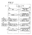
- FIG. 2 is a block diagram showing a configuration of a control section 9 of the image forming apparatus 1 .
- the image forming apparatus 1 is configured of an image forming section 2 , an intermediate transfer section 3 , a secondary transfer section 4 , a recording material feed section 5 , and a fixing device 6 .
- the image forming apparatus 1 is equipped with, apart from each above-described section and the like, a display section 7 a formed of a liquid crystal display (LCD), an operating section 7 b including various kinds of keys, and the control section 9 controlling each above-described section and the like.
- a display section 7 a formed of a liquid crystal display (LCD)
- an operating section 7 b including various kinds of keys
- the control section 9 controlling each above-described section and the like.
- control section 9 is configured of a central processing unit (CPU) 9 a , a hard disc drive (HDD) 9 b , a memory 9 c , a display section control circuit 9 d , an operating section control circuit 9 e , a local area network (LAN) control circuit 9 f , an image forming section control circuit 2 a , an intermediate transfer section control circuit 3 a , a secondary transfer section control circuit 4 a , a recording material feed section control circuit 5 a , and a fixing device control circuit 6 a.
- CPU central processing unit
- HDD hard disc drive
- the CPU 9 a being configured of a microprocessor, software such as an operating system (OS) and various kinds of control program and application program, to be used for controlling the image forming apparatus 1 , is stored in the HDD 9 b , and the CPU 9 a , based on the software, carries out various kinds of control and process.
- OS operating system
- control program and application program to be used for controlling the image forming apparatus 1
- the display section control circuit 9 d is used to carry out an operational control of the display section 7 a , the operating section control circuit 9 e of the operating section 7 b , the LAN control circuit 9 f of a LAN interface, the image forming section control circuit 2 a of the image forming section 2 , the intermediate transfer control circuit 3 a of the intermediate transfer section 3 , the secondary transfer section control circuit 4 a of the secondary transfer section 4 , the fixing device control circuit 6 a of the fixing device 6 , and the recording material feed section control circuit 5 a of the recording material feed section 5 .
- the recording material feed section 5 is configured of a recording paper storage tray 42 which stores recording paper 8 which is a recording material, a recording paper discharge roller 43 which discharges the recording paper 8 stored in the recording paper storage tray 42 , conveyance rollers 44 a and 44 b which convey the discharged recording paper 8 to the secondary transfer section 4 , and a conveyance path P.
- the image forming section 2 includes image forming units 10 y , 10 m , 10 c , and 10 b which form electrostatic latent images which correspond to digital signals (hereinafter described as image information) of the respective colors, develop the latent images and form the toner images with toner of each color. That is, the image forming unit 10 y forms a toner image corresponding to yellow image information. The image forming unit 10 m forms a toner image corresponding to magenta image information. The image forming unit 10 c forms a toner image corresponding to cyan image information. The image forming unit 10 b forms a toner image corresponding to black image information.
- image information digital signals
- the image forming units 10 y , 10 m , 10 c , and 10 b are of the same configuration except that a yellow developer, magenta developer, cyan developer, and black developer are used in the respective image forming units, and that, among pieces of image information inputted into the image forming section 2 , a pixel signal corresponding to a yellow component image, a pixel signal corresponding to a magenta component image, a pixel signal corresponding to a cyan component image, and a pixel signal corresponding to a black component image are inputted into the respective image forming units, hereafter, the image forming unit 10 y for yellow will be shown as a representative example, and a description of the others will be omitted.
- the image forming units 10 and the like for the individual colors, when separately shown, will be represented with alphabetical suffixes: y (yellow), m (magenta), c (cyan), and b (black), affixed thereto.
- the image forming units 10 y , 10 m , 10 c , and 10 b are arranged into a line in the order named, from an upstream side to a downstream side, in a direction of movement (a sub-scanning direction) of an intermediate transfer belt 21 which is an intermediate transfer medium, that is, in the direction of an arrow 27 .
- FIG. 3 is a schematic diagram showing a configuration of the image forming unit 10 y .
- the image forming unit 10 y includes a photoreceptor drum 11 y , on the surface of which a yellow toner image is formed, a charging roller 12 y , which uniformly charges the surface of the photoreceptor drum 11 y , an optical scanning unit 13 y , which exposes the charged surface of the photoreceptor drum 11 y to light corresponding to the image information, forming an electrostatic latent image, a developing device 14 y , which forms a toner image by attaching toner to the electrostatic latent image formed on the surface of the photoreceptor drum 11 y , and a drum cleaner 15 y , which removes and collects toner remaining on the surface of the photoreceptor drum 11 y without being intermediately transferred to the intermediate transfer belt 21 .
- the photoreceptor drum 11 y is a latent image bearing member which, by being exposed to the light corresponding to the image information, has an electrostatic latent image formed on the surface thereof, and is provided so as to be rotatable.
- the photoreceptor drum 11 y being supported so as to be able to be rotationally driven around its axis by a driving portion (not shown), includes a cylindrical, columnar, or thin film sheet-like (preferably, cylindrical) conductive substrate (not shown) and a photosensitive layer (not shown) formed on the surface of the conductive substrate.
- a photoreceptor drum 11 y which, being connected to a ground (GND) potential, includes an aluminum base tube which is the conductive substrate, and an organic photosensitive layer which is the photosensitive layer formed on the surface of the aluminum base tube.
- GND ground
- the organic photosensitive layer may be one formed laminating a charge generating layer including a charge generating substance, and a charge transporting layer including a charge transporting substance, or may be one having the charge generating substance and charge transporting substance included in one layer.
- the thickness of the organic photosensitive layer is not particularly limited but is, for example, 20 ⁇ m.
- an undercoat layer between the organic layer and conductive substrate may be provided.
- a protecting layer may be provided on the surface of the organic photosensitive layer.
- the photoreceptor drum 11 y rotates at a circumferential speed of, for example, 220 mm/s in a counterclockwise direction as seen facing the plane of FIG. 3 .
- the driving portion of the photoreceptor drum 11 y is controlled by the image forming section control circuit 2 a , thereby controlling the rotation speed of the photoreceptor drum 11 y.
- the charging roller 12 y is a charging section which charges the surface of the photoreceptor drum 11 y with potential of predetermined polarity.
- As the charging section it is not limited to only the charging roller 12 y and the charging roller 12 y can be replaced by a brush-type charging device, a charger-type charging device, or a corona charging device such as a scorotron charger.
- the optical scanning unit 13 y is a latent image forming section which irradiates the charged surface of the photoreceptor drum 11 y with a laser beam corresponding to the yellow image information, and forms an electrostatic latent image corresponding to the yellow image information on the surface of the photoreceptor drum 11 y .
- a semiconductor laser element or the like is used as a laser beam light source.
- the developing device 14 y is a developing section which, being provided facing the photoreceptor drum 11 y , limits a yellow developer 16 y including a yellow toner and a carrier to a predetermined amount by means of a layer thickness limitation member 18 y , bears it on the surface of a developing sleeve 17 y , conveys it to the surface of the photoreceptor drum 11 y , and develops and visualizes the electrostatic latent image formed on the surface of the photoreceptor drum 11 y .
- the developing device 14 y it is also possible to use one using a one-component developer including no carrier, or the like.
- the developing sleeve 17 y is rotationally driven in the same direction as a direction of rotational drive of the photoreceptor drum 11 y , in a developing nip region which is close to the photoreceptor drum 11 y . Consequently, a direction of rotational drive around the axis of the developing sleeve 17 y is opposite to the direction of rotational drive of the photoreceptor drum 11 y.
- the drum cleaner 15 y removes and collects a yellow toner remaining on the surface of the photoreceptor drum 11 y after the yellow toner image on the surface of the photoreceptor drum 11 y is intermediately transferred to the intermediate transfer belt 21 .
- the toner comprises toner particles each containing a binder resin, a colorant, and a release agent.
- a binder resin ingredients customarily used in this field can be used, and examples thereof include polystyrene, a homopolymer of styrene substitute, a styrene-type copolymer, polyvinyl chloride, polyvinyl acetate, polyethylene, polypropylene, polyester, and polyurethane.
- the binder resins may be used each alone, or two or more thereof may be used in combination.
- the binder resin which has a softening temperature of 100° C. to 150° C. and a glass transition temperature of 50° C. to 80° C.
- polyester which has a softening temperature and a glass transition temperature in the above ranges, from the aspect of storage stability, durability, etc. Polyester in a softened or fused state is high in transparency.
- polyester when a multicolor toner image composed of combined toner images of yellow, magenta, cyan, and black, is fixed on a recording sheet 8 , the polyester itself becomes transparent, leading to sufficient color development by subtractive color mixture.
- the colorant it is possible to use pigments and dyes for toner which have been conventionally used in the electrophotographic image forming technique.
- the pigment include an organic pigment such as azo pigment, benzimidazolone pigment, quinacridone pigment, phthalocyanine pigment, isoindolinone pigment, isoindoline pigment, dioxazine pigment, anthraquinone pigment, perylene pigment, perynone pigment, thioindigo pigment, quinophthalone pigment, or metal complex pigment; an inorganic pigment such as carbon black, titanium oxide, molybdenum red, chrome yellow, titanium yellow, chrome oxide, or Berlin blue; and metal powder such as aluminum powder.
- the pigments may be used each alone, or two or more thereof may be used in combination.
- wax can be used, for example. It is possible to use the wax which is customarily used in this field, and examples thereof include polyethylene wax, polypropylene wax, and paraffin wax.
- the toner may contain, other than the binder resin, colorant, and release agent, one or two or more additives for general use in toner, such as a charge control agent, a fluidity improving agent, a fixing promoting agent, and a conductive agent.
- the toner can be manufactured according to the above known methods such as a pulverization method, a suspension polymerization method, and an emulsification coagulation method.
- a pulverization method the colorant, the release agent, etc. are melt-kneaded together with the binder resin, followed by pulverization.
- the suspension polymerization method the colorant, the release agent, a monomer of the binder resin, etc. are evenly dispersed, followed by polymerization of the monomer of the binder resin.
- the emulsification coagulation method binder resin particles, the colorant, the release agent, etc., are coagulated with the aid of a coagulant, and fine particles of a thus-obtained coagulated product are heated.
- the volume average particle size of the toner is not particularly limited, but is preferably 2 to 7 ⁇ m. Also, in the event that the volume average particle size of the toner is appropriately small in this way, as the fraction of coverage of the recording material is high, it is possible to achieve an increase in image quality with a small amount of toner attached, and a decrease in toner consumption.
- the toner When the volume average particle size of the toner is less than 2 ⁇ m, the toner may be degraded in fluidity, leading to insufficient supply, stirring, and charging of the toner upon the developing operation. This may cause a shortage of the toner amount, an increase of toner of reverse polarity, and the like problem, which possibly leads to a failure in forming high-quality images.
- the volume average particle size of the toner exceeds 7 ⁇ m, a larger amount of the toner particles has such a large size that a center part of each toner particle is hard to be soften, with the result that a fixing property of the image onto the recording sheet 8 is degraded and moreover, the color development of the image is lower. And particularly in the case of fixing the image onto an OHP sheet, an obtained image is darker.
- the toner of respective colors used in the embodiment, except the colorant has the same configuration as follows.
- the toner is, for example, a negatively-charged nonmagnetic insulating toner which has a glass transition temperature of 60° C., a softening temperature of 120° C., and a volume average particle size of 6 ⁇ m.
- a required toner amount is 5 g/m 2 .
- the toner contains polyester having a glass transition temperature of 60° C. and a softening temperature of 120° C.
- a low-molecular polyethylene wax having a glass transition temperature of 50° C. and a softening temperature of 70° C. as the release agent, and pigments of respective colors as colorant A content of the wax is 7% by weight of the total amount of the toner while a content of the pigment is 12% by weight of the total amount of the toner, with the binder resin, i.e., polyester which occupies a remaining part of the total amount of the toner.
- the low-molecular polyethylene wax contained in the toner is wax whose glass transition temperature and softening temperature are lower than those of the polyester serving as the binder resin.
- the developers 16 y , 16 m , 16 c , and 16 b may be a two-component developer including a carrier in addition to the toner.
- a carrier it is possible to use magnetic particles.
- the magnetic particles it is possible to propose, for example, a metal such as iron, ferrite, or magnetite, or an alloy of these metals and a metal such as aluminum or lead. Among them, ferrite is preferable.
- a resin coated carrier having magnetic particles coated with a resin, a resin dispersion type carrier having magnetic particles dispersed on a resin, or the like, may be used as the carrier.
- the resin coating the magnetic particles although it is not particularly limited, examples thereof include an olefin resin, styrene resin, styrene/acrylic resin, silicone resin, ester resin, and fluorine-containing polymer resin.
- the resin used in the resin dispersion type carrier although it is not particularly limited, examples thereof include a styrene acrylic resin, polyester resin, fluorine resin, and phenol resin.
- the shape of the carrier is a spherical or flat shape.
- the volume average particle size of the carrier is not particularly limited but, considering the increase in image quality, is preferably 30 ⁇ m or more to 50 ⁇ m or less.
- the resistivity of the carrier is preferably 10 8 ⁇ cm or more, and more preferably, 10 12 ⁇ cm or more.
- the resistivity of the carrier is a value obtained by reading a current value when, after putting the carrier in a container having a cross-sectional area of 0.50 cm 2 , and tapping it, applying a load of 1 kg/cm 2 to particles filling the container, and applying a voltage which causes an electric field of 1000 V/cm between the load and a bottom electrode.
- the magnetization intensity (maximum magnetization) of the carrier is preferably 10 emu/g to 60 emu/g, and more preferably, 15 emu/g to 40 emu/g.
- the magnetization intensity depends on the magnetic flux density of the developing sleeves 17 y , 17 m , 17 c , and 17 b , under conditions of the general magnetic flux density of the developing sleeves 17 y , 17 m , 17 c , and 17 b , there is a fear that no magnetic constraint force acts in the event of less than 10 emu/g, causing a carrier dispersion.
- a ratio of toner and carrier used in the developers 16 y , 16 m , 16 c , and 16 b is not particularly limited, and it is sufficient to appropriately select it depending on the type of toner and carrier.
- the image forming unit 10 y for example, 1200 V is applied to the charging roller 12 y by a power source (not shown) while rotationally driving the photoreceptor drum 11 y around its axis, and the photoreceptor drum 11 y is discharged, thereby charging the surface of the photoreceptor drum 11 y to, for example, 600 V.
- the charged surface of the photoreceptor drum 11 y is irradiated with the laser beam corresponding to the yellow image information from the optical scanning unit 13 y , forming an electrostatic latent image with an exposure potential of ⁇ 70 V corresponding to the yellow image information.
- the surface of the photoreceptor drum 11 y and the yellow developer borne on the surface of the developing sleeve 17 y are brought into proximity with one another.
- a direct current voltage of ⁇ 450 V is applied to the developing sleeve 17 y as a development potential, and the yellow toner adheres to the electrostatic latent image due to a difference in potential between the developing sleeve 17 y and the photoreceptor drum 11 y , forming the yellow toner image on the surface of the photoreceptor drum 11 y .
- the yellow toner image is brought into pressure-contact with the surface of the photoreceptor drum 11 y , and intermediately transferred to the intermediate transfer belt 21 driven in the direction of the arrow 27 .
- a yellow toner remaining on the surface of the photoreceptor drum 11 y is removed and collected by the drum cleaner 15 y .
- a yellow toner image forming operation will be repeatedly executed in the same way.
- the intermediate transfer section 3 includes the intermediate transfer belt 21 , intermediate transfer rollers 22 y , 22 m , 22 c , and 22 b , supporting rollers 23 , 24 , and 25 , and a belt cleaner 26 .
- the intermediate transfer belt 21 is an endless belt shaped image bearing member which is supported around the supporting rollers 23 , 24 , and 25 with tension to thereby form a loop-like travel path, and is rotationally driven in the direction of the arrow 27 at approximately the same circumferential speed as that of the photoreceptor drums 11 y , 11 m , 11 c , and 11 b , that is, so that an image bearing surface facing the photoreceptor drums 11 y , 11 m , 11 c , and 11 b moves from the photoreceptor drum 11 y toward the photoreceptor drum 11 b.
- the intermediate transfer belt 21 it is possible to use, for example, a 100 ⁇ m thick polyimide film.
- a material of the intermediate transfer belt 21 it not being limited to polyimide, it is possible to use a film configured of a synthetic resin, such as polycarbonate, polyamide, polyester, or polypropylene, various kinds of rubber, or the like.
- the film made of a synthetic resin or any kind of rubber contains an electrically conductive material, such as furnace black, thermal black, channel black, or graphite carbon, in order to adjust an electric resistance value with which it acts as the intermediate transfer belt 21 .
- a covering layer configured of a fluorine resin composition, fluorine-containing rubber, or the like, which has a low adhesion to toner, may be provided on the intermediate transfer belt 21 .
- a component material of the covering layer examples thereof include polytetrafluoroethylene (PTFE) and PFA (a copolymer of PTFE and perfluoroalkyl vinyl ether).
- the covering layer may contain an electrically conductive material.
- a toner image bearing surface of the intermediate transfer belt 21 comes into pressure-contact with the photoreceptor drums 11 y , 11 m , 11 c , and 11 b in the order just stated from the upstream side in the rotational direction of the intermediate transfer belt 21 .
- Positions where the intermediate transfer belt 21 comes into pressure-contact with the photoreceptor drums 11 y , 11 m , 11 c , and 11 b are positions where toner images of respective colors are transferred.
- the intermediate transfer rollers 22 y , 22 m , 22 c , and 22 b are roller members which are respectively opposed to the photoreceptor drums 11 y , 11 m , 11 c , and 11 b with the intermediate transfer belt 21 interposed therebetween and come into pressure-contact with a reverse side of the toner image bearing surface 21 a of the intermediate transfer belt 21 and which are disposed so as to be rotationally driven about respective axial line of the rollers by a driving portion (not shown).
- a roller member is used, for example, which is composed of a metallic shaft and a conductive layer covering a surface of the metallic shaft.
- the metallic shaft is, for example, formed of a metal such as stainless steel.
- a diameter of the metallic shaft is not particularly limited, and preferably from 8 mm to 10 mm.
- the conductive layer is formed of a conductive elastic body or the like material.
- the conductive elastic body a material customarily used in this field is applicable, and examples thereof include ethylene-propylene rubber (hereinafter described as EPDM), foamed EPDM, and urethane foam, which contain a conductive material such as carbon black. Owing to the conductive layer, high voltage is evenly applied to the intermediate transfer belt 21 .
- intermediate transfer belt 21 Owing to the conductive layer, high voltage is evenly applied to the intermediate transfer belt 21 . Since the toner images formed on the surfaces of the photoreceptor drum 11 y , 11 m , 11 c , and 11 b are transferred onto the intermediate transfer belt 21 , intermediate transfer bias voltage is applied to the intermediate transfer rollers 22 y , 22 m , 22 c , and 22 b through a constant voltage control, which bias has a polarity reverse to that of the polarity of the charged toner.
- the toner images of yellow, magenta, cyan, and black formed on the photoreceptor drums 11 y , 11 m , 11 c , and 11 b are sequentially transferred and overlaid on top of one another on the toner image bearing surface of the intermediate transfer belt 21 , thus forming a multicolor toner image.
- a toner image is formed by only an image forming unit 10 corresponding to a color of inputted image information, among the image forming units 10 y , 10 m , 10 c , and 10 b.
- the supporting rollers 23 , 24 , and 25 are disposed so as to be rotationally driven about respective axes thereof by a driving portion (not shown), support the intermediate transfer belt 21 therearound with tension and rotated in the direction of the arrow 27 by the supporting rollers 23 , 24 , and 25 .
- an aluminum-made cylinder (a pipe-shaped roller) is used, for example, having a diameter of 30 mm and a thickness of 1 mm.
- the supporting roller 24 comes into pressure-contact with a later-described secondary transfer roller 28 with the intermediate transfer belt 21 interposed therebetween, thus forming a secondary transfer nip region, and is electrically grounded.
- the supporting roller 24 has a function of support the intermediate transfer belt 21 therearound with tension together with a function of secondarily transferring the toner image on the intermediate transfer belt 21 onto the recording sheet 8 .
- the belt cleaner 26 is a member for removing the toner which remains on the image bearing surface after the toner image on the bearing surface of the intermediate transfer belt 21 is transferred onto the recording sheet 8 in the later-described secondary transfer section 4 .
- the belt cleaner 26 is disposed opposite to the supporting roller 25 with the intermediate transfer belt 21 interposed therebetween.
- the toner image is secondarily transferred to the recording paper 8 in a secondary transfer nip region. Toner, paper powder, and the like remaining on the image bearing surface of the intermediate transfer belt 21 after the secondary transfer are removed by the belt cleaner 26 , and a toner image is transferred again to the image bearing surface.
- the secondary transfer section 4 includes a supporting roller 24 and a secondary transfer roller 28 , as shown in FIG. 1 .
- the secondary transfer roller 28 is a roller member which comes into pressure-contact with the supporting roller 24 with the intermediate transfer belt 21 interposed therebetween, is provided so as to be able to be rotationally driven about its axis.
- the secondary transfer roller 28 includes, for example, a metallic shaft body and an electrically conductive layer covering the surface of the metallic shaft body.
- the metallic shaft body is formed of a metal such as, for example, stainless steel.
- the electrically conductive layer is formed of an electrically conductive elastic body or the like.
- the electrically conductive elastic body although it is possible to use one commonly used in this field, examples thereof include EPDM, EPDM foam, or urethane foam, which includes an electrically conductive material such as carbon black.
- a power source (not shown) is connected to the secondary transfer roller 28 , and a high voltage with a polarity, the reverse of a toner particle charging polarity, is uniformly applied thereto.
- a pressure-contact region of the supporting roller 24 , intermediate transfer belt 21 , and secondary transfer roller 28 are a secondary transfer nip region.
- the secondary transfer section 4 in synchronism with the toner image on the intermediate transfer belt 21 being conveyed to the secondary transfer nip region, the recording paper 8 fed from the previously described recording material feed section 5 is conveyed to the secondary transfer nip region. Then, by the toner image and the recording paper 8 being overlaid one on the other in the secondary transfer nip region, and the high voltage with the polarity, the reverse of the toner charging polarity, being uniformly applied to the secondary transfer roller 28 , an image formed from toner is secondarily transferred to the recording paper 8 . Then, the recording paper 8 bearing the toner image is conveyed to the fixing device 6 .
- FIG. 4 is a schematic diagram showing a configuration of the fixing device 6 .
- the fixing device 6 includes a heating roller 50 which is a main heating section, a pressure roller 60 which is a pressure section, and an external heating section 70 , as shown in FIG. 4 .
- the heating roller 50 is a roller member which is rotatably supported by a supporting portion (not shown) and which rotates at a predetermined velocity in a direction of an arrow 56 by a driving portion (not shown).
- the heating roller 50 is used to heat and thus fuse the toner constituting the toner image borne on the recording sheet 8 .
- a roller member is used which is composed of a metal core 51 , an elastic layer 52 , and a surface layer 53 .
- a usable metal for forming the metal core 51 is a metal having high thermal conductivity such as aluminum and iron.
- Shape examples of the metal core 51 include a cylindrical shape, a columnar shape, and the like shape etc., and preferable is the cylindrical shape which discharges a small amount of heat from the metal core 51 .
- any material having rubber elasticity may be used without particular limitation, and preferably used is a material which is also excellent in heat resistance. Specific examples of such a material include silicone rubber, fluoro-rubber, and fluorosilicone rubber. Among these materials, preferable is the silicone rubber which is particularly excellent in rubber elasticity.
- any material may be used without particular limitation as long as the material has excellent heat resistance and durability and weak adherence to the toner.
- the material of the surface layer 53 include a fluorine resin material such as PFA (tetrafluoroethylene-perfluoroalkylvinylether copolymer) and PTFE (polytetrafluoroethylene), and a fluoro-rubber.
- the surface layer 53 is an about 40 ⁇ m-thick PFA layer.
- a heat source 54 is provided inside the heating roller 50 . This is used to shorten a start-up period of time of the image forming apparatus 1 after turning on the power source thereof until a state ready for image formation is set, and prevent a surface temperature of the heating roller 50 from lowering which is caused by heat transfer to the recording sheet 8 in fixing the toner image.
- a halogen lamp is used for the heat source 54 .
- the pressure roller 60 is a roller member which is disposed so as to be rotatable in pressure-contact with the heating roller 50 by a pressurizing mechanism (not shown), in downstream of the lowest point in a vertical direction of the heating roller 50 in a rotational direction of the heating roller 50 .
- a pressure-contact region between the heating roller 50 and the pressure roller 60 is a fixing nip region 55 .
- the pressure roller 60 makes the toner image heated to be fixed onto the recording sheet in cooperation with the heating roller 50 . At this time, the pressure roller 60 presses the fused toner against the recording medium 8 to thereby promote the fixing of the toner image onto the recording medium 8 .
- a roller member having a diameter of 40 mm which is composed of a metal core 61 , an elastic layer 62 , and a surface layer 63 .
- Usable materials for forming the metal core 61 , the elastic layer 62 , and the surface layer 63 are respectively the same metal or material which forms the metal core 51 , elastic layer 52 , and surface layer 53 of the heating roller 50 .
- a shape of the metal core 61 is also the same as that in the case of the heating roller 50 .
- a heat source 64 is provided inside the pressure roller 60 .
- a halogen lamp is used for the heat source 64 .
- the external heating section 70 includes an endless belt 71 , and two supporting rollers, which are a first supporting roller 72 , and a second supporting roller 73 , thermistors 76 and 78 which are temperature detecting members, and the thermostat 77 .
- the endless belt 71 is an endless belt-shaped member which is supported around the first supporting roller 72 and the second supporting roller 73 with tension to thereby form a loop-like travel path.
- the endless belt 71 is arranged so as to come into contact with the heating roller 50 in a band-shaped region which extends along a longitudinal direction of the fixing roller over a length in an outer circumferential direction of the heating roller 50 from a pressure-contact point between the first supporting roller 72 and the heating roller 50 to a pressure-contact point between the second supporting roller 73 and the heating roller 50 . Further, the endless belt 71 is driven to rotate in a direction of an arrow 79 by rotation of the heating roller 50 in the direction of the arrow 56 .
- any belt can be used without particular limitation as long as the belt is excellent in heat-resistance and durability. Examples of materials of the endless belt 71 include a polyimide-made belt and an electroformed nickel belt.
- a surface of the endless belt 71 may be provided with a fluorine resin layer which is made of PFA, PTFE, or the like material.
- a 100 ⁇ m-thick endless belt is used which is formed into a cylindrical shape having a diameter of 31 mm.
- the first supporting roller 72 and the second supporting roller 73 are roller members which are rotatably supported and disposed so as to come into pressure-contact with a surface of the heating roller 50 with the endless belt 71 interposed therebetween by a pressure mechanism (not shown).
- the first supporting roller 72 and the second supporting roller 73 are driven to rotate by rotation of the endless belt 71 in the direction of the arrow 79 .
- metallic rollers can be used, each of which is made of a metal having high thermal conductivity such as aluminum and iron.
- a fluorine resin layer may be formed according to need.
- the first supporting roller 72 and the second supporting roller 73 contain therein heat sources 74 and 75 , respectively.
- the heat sources 74 and 75 are connected to a power source, and electric power is supplied to cause the heat sources 74 and 75 to generate heat.
- a commonly-used heat source can be used as the heat sources 74 and 75 .
- a halogen lamp is used for each of heat sources 74 and 75 .
- the first supporting 72 and the second supporting 73 are disposed so as to have respective axial lines thereof in parallel with each other on the heating roller 50 and so as to be distanced away from each other.
- the thermistor 76 is provided so as to be close to the endless belt 71 in a position facing the second supporting roller 73 across the endless belt 71 , and detects a second temperature which is the temperature of a portion of the endless belt 71 in which the endless belt 71 is in contact with the second supporting roller 73 .
- the thermistor 78 is provided so as to be close to the endless belt 71 in a position facing the first supporting roller 72 across the endless belt 71 , and detects a second temperature which is the temperature of a portion of the endless belt 71 in which the endless belt 71 is in contact with the first supporting roller 72 .
- the thermostat 77 is provided so as to be close to the endless belt 71 in a position facing the second supporting roller 73 across the endless belt 71 and downstream of the thermistor 76 in a direction of rotation of the endless belt 71 , and detects an abnormal increase in temperature of the endless belt 71 .
- the above-described fixing device 6 is controlled by the fixing device control circuit 6 a of the control section 9 , as described above. That is, an operation of a fixing mechanism including the heating roller 50 , pressure roller 60 , and external heating section 70 is controlled by the fixing device control circuit 6 a.
- the CPU 9 a on receiving an input of an image formation instruction, sends a control signal to a power source which feeds electric power to heat sources 54 , 64 , 74 , and 75 provided respectively inside the heating roller 50 , pressure roller 60 , and first and second supporting rollers 72 and 73 .
- the image formation instruction is inputted from external equipment such as the operating section 7 b provided on the upper surface of the image forming apparatus 1 , or a computer connected to the image forming apparatus 1 via a LAN.
- the power source which has received the control signal feeds electric power, activating the heat sources 54 , 64 , 74 , and 75 .
- the heat sources 54 , 64 , 74 , and 75 heat the heating roller 50 , pressure roller 60 , and the endless belt 71 so that the surfaces thereof reach their respective setting temperatures.
- a temperature detecting sensor (not shown), which is disposed near the heating roller 50 and the pressure roller 60 , detects that temperatures of the above components have reached the set temperatures and such a detected result inputted to the CPU 9 a , the CPU 9 a sends a control signal to a driving portion (not shown) for rotating the heating roller 50 , thereby driving the heating roller 50 to rotate in the direction of the arrow 56 .
- the driving of the heating section 50 also drives the pressure roller 60 and thus the heating belt 71 .
- the recording sheet 8 bearing the unfixed toner image is conveyed from the secondary transfer section 4 to the fixing nip region 55 .
- the toner constituting the toner image is heated and pressurized to be thereby fixed on the recording sheet 8 , resulting in an image.
- the warming-up operation is controlled by the fixing device control circuit 6 a of the control section 9 .
- the heat sources 74 and 75 of the external heating section 70 provided in the fixing device 6 are powered on. After the endless belt 71 of the external heating section 70 is heated as far as a first temperature T 1 , a drive motor of the heating roller 50 starts to be rotated. In the event of using the kind of belt type in the embodiment for the external heating section 70 , when the endless belt 71 is at a low temperature, the endless belt 71 does not rotate easily due to being impressed by the first and second supporting rollers 72 and 73 . For this reason, the drive motor of the heating roller 50 is rotated after the temperature of the endless belt 71 is increased to the temperature T 1 at which the belt 71 is sufficiently softened. In order to effectively heat the surface of the heating roller 50 , the heat sources 74 and 75 of the external heating section 70 continue to be powered on even after the start of rotation of the drive motor.
- the ON/OFF control of the heat sources 74 and 75 is carried out so as to maintain the belt temperature at T 3 .
- T 3 a temperature
- the feed of electric power to the heat sources 74 and 75 of the external heating section 70 is cut off, the feed of electric power is switched to the heat source 54 of the heating roller 50 , and the heat source 54 is powered on.
- T 4 a target temperature
- the warming-up operation is finished at a point at which the heating roller 50 has reached the target temperature T 4 .
- a temperature adjustment is carried out for a target temperature in a standby mode while idling the heating roller 50 for 30 seconds after the finishing of the warming-up operation.
- An operational mode switches to the standby mode after a lapse of 30 seconds from the finishing of the warming-up operation, stopping the rotation of the drive motor of the heating roller 50 . At this time, as the inside of the heating roller 50 is not sufficiently heated, a decrease in temperature of the heating roller 50 occurs.
- a heating is carried out by feeding electric power to the halogen lamp 54 which is the heat source of the heating roller 50 .
- the feed of electric power to the halogen lamp 54 is stopped at a point at which t 1 seconds have elapsed after electric power is fed to the halogen lamp 54 , or the surface temperature of the heating roller 50 has reached T 5 ( ⁇ T 4 ).
- the feed of electric power to the halogen lamp 54 is maintained in the stopped condition for t 2 seconds after the feed of electric power to the halogen lamp 54 is stopped.
- the surface temperature of the heating roller 50 is detected t 2 seconds after the stopping of the feed of electric power to the halogen lamp 54 and, in the event that it is T 5 or less, electric power is fed again to the halogen lamp 54 .
- the heating roller 50 ceases to be heated at a point at which the temperature thereof is T 5 , which is lower than the target temperature T 4 , it is possible to reduce an overshoot of the surface temperature of the heating roller 50 without a metal core 51 of the heating roller 50 being heated to excess, even when the operational mode is shifted from the warming-up to the standby mode.
- the heating is controlled so that the temperature of the metal core 51 is 240° C. or less.
- the temperature of the metal core 51 is 240° C. or less.
- FIG. 5 is a flowchart showing a heating control of the fixing device 6 in a condition in which the temperature thereof is stabilized in the standby mode.
- FIG. 6 is a graph showing the surface temperature of the heating roller 50 and an operation timing of the halogen lamp 54 .
- the horizontal axis indicates time, and the vertical axis indicates the surface temperature of the heating roller 50 .
- step S 1 The surface temperature of the heating roller 50 is detected, and it is determined in step S 1 whether or not it has decreased to a temperature equal to or less than a temperature T 6 ( ⁇ T 5 ). If it has decreased, the process proceeds to step S 2 , and if it has not decreased, the process waits. In step S 2 , electric power is fed to the halogen lamp 54 .
- step S 3 it is determined whether t 1 seconds have elapsed after electric power is fed to the halogen lamp 54 , or the surface temperature of the heating roller 50 has reached the temperature T 5 .
- step S 4 stopping the feed of electric power to the halogen lamp 54 . If t 1 seconds have not elapsed, and the temperature T 5 has not been reached either, the process returns to step S 2 , continuing the heating.
- step S 5 It is determined in step S 5 whether or not t 2 seconds have elapsed after the feed of electric power to the halogen lamp 54 is stopped, and if t 2 seconds have elapsed, the process returns to step S 1 , while if t 2 seconds have not elapsed, the feed of electric power continues to be stopped.
- the invention may be realized by means of a program and a recording medium on which the program is recorded.
- a heating control CPU central processing unit which executes a command of a control program realizing each function
- a read only memory which stores the program
- a random access memory which expands the program
- a storage device (a recording medium) such as a memory which stores the program and various data, and the like, are included, and a temperature control device is constituted by them.
- the object of the invention can also be achieved by supplying to the temperature control device the recording medium on which program codes (an execute form program, an intermediate code program, and a source program) of the temperature control program which is the software realizing the above-described functions are recorded so as to be readable by a computer, and retrieving and executing the program codes stored in the recording medium by the computer (or a CPU or MPU).
- program codes an execute form program, an intermediate code program, and a source program
- a tape system such as a magnetic tape or cassette tape
- a disk system including a magnetic disk such as a floppy (registered trademark) disk or hard disk, or an optical disk such as a CD-ROM, an MO, an MD, a DVD, or a CD-R
- a card system such as an IC card (including a memory card) or optical card
- a semiconductor memory system such as a mask ROM, an EPROM, an EEPROM, or a flash ROM.
- the temperature control device may be configured so as to be connectable to a communication network, and the program codes may be supplied via the communication network.
- the communication network which is not particularly limited, it is possible to utilize, for example, the Internet, an intranet, an extranet, a LAN, an ISDN, a VAN, a CATV communication network, a virtual private network, a telephone network, a mobile communication network, or a satellite communication network.
- a transmission medium constituting the communication network which is not particularly limited, it is possible to utilize, for example, either a wired line such as an IEEE1394, a USB, a power line carrier, a cable TV line, a telephone line, or an ADSL, or a wireless line such as an infrared ray used in an IrDA or a remote control, Bluetooth (registered trademark), an 802.11 wireless LAN, an HDR, a portable telephone network, a satellite connection, or a digital terrestrial network.
- the invention can also be realized in the form of a computer data signal embedded in a carrier wave, in which the program codes are embodied by an electronic transmission.
- the rotation of the drive motor of the heating roller 50 was stopped 30 seconds after the finishing of the warming-up operation, and the heating control was carried out in the standby mode.
- the feed of electric power to the halogen lamp 54 was stopped after a lapse of 9 seconds (t 1 ) from electric power being fed to the halogen lamp 54 of the heating roller 50 .
- the feed of electric power to the halogen lamp 54 was compulsorily stopped for 8 seconds (t 2 ) thereafter. This control was repeatedly carried out until the heating roller reached a target temperature of 200° C.
- the overshoot was 209° C. Also, the maximum temperature of the metal core 51 of the heating roller 50 was 238° C.
- the rotation of the drive motor of the heating roller 50 was stopped 30 seconds after the finishing of the warming-up operation, and the heating control was carried out in the standby mode.
- Electric power was fed to the halogen lamp 54 of the heating roller 50 , and electric power continued to be fed to the halogen lamp 54 until the surface temperature of the heating roller 50 reached 200° C.
- the overshoot was 217° C. Also, the maximum temperature of the metal core 51 of the heating roller 50 was 253° C.
- the heating control was carried out in the condition in which the temperature thereof was stabilized in the standby mode.
- Electric power was fed to the halogen lamp 54 of the heating roller 50 at a point at which the surface temperature of the heating roller 50 had reached 188° C. (T 6 ), and the feed of electric power to the halogen lamp 54 was stopped after a lapse of 2 seconds (t 1 ) from the starting of the feed of electric power.
- the feed of electric power to the halogen lamp 54 was compulsorily stopped for 5 seconds (t 2 ) thereafter. This control was repeatedly carried out until the heating roller reached a target temperature of 190° C.
- the heating control was carried out in the condition in which the temperature thereof was stabilized in the standby mode.
- Electric power was fed to the halogen lamp 54 of the heating roller 50 at a point at which the surface temperature of the heating roller 50 had reached 188° C. (T 6 ), and the feed of electric power to the halogen lamp 54 was stopped after a lapse of 9 seconds (t 1 ) from the starting of the feed of electric power.
- the feed of electric power to the halogen lamp 54 was compulsorily stopped for 8 seconds (t 2 ) thereafter. This control is repeatedly carried out until the heating roller reached a target temperature of 190° C.
- the temperature ripple was 8° C.
- the overshoot was 194° C.
- the maximum temperature of the metal core 51 of the heating roller 50 was 224° C.
- the heating control was carried out in the condition in which the temperature thereof was stabilized in the standby mode.
- Electric power was fed to the halogen lamp 54 of the heating roller 50 at a point at which the surface temperature of the heating roller 50 had reached 188° C. (T 6 ), and the feed of electric power to the halogen lamp 54 was stopped after a lapse of 4 seconds (t 1 ) from the starting of the feed of electric power.
- the feed of electric power to the halogen lamp 54 was compulsorily stopped for 13 seconds (t 2 ) thereafter.
- the temperature ripple was 7° C.
- the overshoot was 193° C.
- the maximum temperature of the metal core 51 of the heating roller 50 was 213° C.
- the heating control was carried out in the condition in which the temperature thereof was stabilized in the standby mode.
- Electric power was fed to the halogen lamp 54 of the heating roller 50 at a point at which the surface temperature of the heating roller 50 had reached 188° C., and electric power continued to be fed to the halogen lamp 54 until the surface temperature of the heating roller 50 reached 190° C. Period of time needed for the electric power feed was 17 seconds.
- the temperature ripple was 17° C.
- the overshoot was 203° C.
- the maximum temperature of the metal core 51 of the heating roller 50 was 235° C.
- the heating control was carried out in the condition in which the temperature thereof was stabilized in the standby mode.
- Electric power was fed to the halogen lamp 54 of the heating roller 50 at a point at which the surface temperature of the heating roller 50 had reached 188° C., and the feed of electric power to the halogen lamp 54 was stopped after a lapse of 2 seconds from the starting of the feed of electric power.
- the feed of electric power to the halogen lamp 54 was compulsorily stopped for 15 seconds thereafter.
- the maximum temperature of the metal core 51 of the heating roller 50 was kept at a low temperature of 210° C., but the heating was not sufficient, and the temperature of the heating roller 50 was 187° C., which was lower than the target temperature.
Abstract
Description
Claims (12)
Applications Claiming Priority (2)
| Application Number | Priority Date | Filing Date | Title |
|---|---|---|---|
| JP2008-218855 | 2008-08-27 | ||
| JP2008218855A JP4764907B2 (en) | 2008-08-27 | 2008-08-27 | Fixing device, image forming apparatus including the same, temperature control program, and recording medium recording temperature control program |
Publications (2)
| Publication Number | Publication Date |
|---|---|
| US20100054788A1 US20100054788A1 (en) | 2010-03-04 |
| US8027608B2 true US8027608B2 (en) | 2011-09-27 |
Family
ID=41725640
Family Applications (1)
| Application Number | Title | Priority Date | Filing Date |
|---|---|---|---|
| US12/546,926 Expired - Fee Related US8027608B2 (en) | 2008-08-27 | 2009-08-25 | Fixing device, image forming apparatus equipped therewith, and recording medium on which temperature control program is recorded |
Country Status (3)
| Country | Link |
|---|---|
| US (1) | US8027608B2 (en) |
| JP (1) | JP4764907B2 (en) |
| CN (1) | CN101661259B (en) |
Cited By (4)
| Publication number | Priority date | Publication date | Assignee | Title |
|---|---|---|---|---|
| US20100303496A1 (en) * | 2009-05-28 | 2010-12-02 | Takashi Mukai | Fixing device, image forming apparatus, and method for controlling fixing device |
| US20110006051A1 (en) * | 2009-07-13 | 2011-01-13 | Canon Kabushiki Kaisha | Image heating apparatus |
| US9727009B2 (en) | 2015-09-25 | 2017-08-08 | Kabushiki Kaisha Toshiba | Fixing device and image forming apparatus |
| US10073384B2 (en) | 2014-06-30 | 2018-09-11 | Hp Indigo B.V. | Print blanket temperature control during pause phases |
Families Citing this family (4)
| Publication number | Priority date | Publication date | Assignee | Title |
|---|---|---|---|---|
| US8561880B2 (en) * | 2012-02-11 | 2013-10-22 | International Business Machines Corporation | Forming metal preforms and metal balls |
| JP5995141B2 (en) * | 2012-10-30 | 2016-09-21 | 株式会社リコー | Image forming apparatus |
| JP5915866B2 (en) * | 2013-12-11 | 2016-05-11 | コニカミノルタ株式会社 | Image forming apparatus |
| WO2016052758A1 (en) * | 2014-10-03 | 2016-04-07 | キヤノン株式会社 | Image heating device |
Citations (12)
| Publication number | Priority date | Publication date | Assignee | Title |
|---|---|---|---|---|
| JPS63173088A (en) | 1987-01-13 | 1988-07-16 | Konica Corp | Device for fixing image forming device |
| JPH0234885A (en) | 1988-07-25 | 1990-02-05 | Ricoh Co Ltd | Thermal fixing device for image forming device |
| JPH05224560A (en) | 1992-02-18 | 1993-09-03 | Mita Ind Co Ltd | Fixing device for image forming machine |
| US5701556A (en) * | 1994-01-31 | 1997-12-23 | Fujitsu Limited | Thermal fixing device having temperature control |
| JPH1124489A (en) | 1997-06-27 | 1999-01-29 | Fuji Xerox Co Ltd | Fixing device for image forming device |
| JP2005202187A (en) | 2004-01-16 | 2005-07-28 | Konica Minolta Business Technologies Inc | Fixing device and image forming apparatus |
| US7254352B2 (en) * | 2003-01-07 | 2007-08-07 | Samsung Electronics Co., Ltd. | Temperature control method for use in a fusing device of an image forming apparatus having a fusing roller and a heater heating the fusing roller and image forming apparatus using the same |
| US20070212093A1 (en) * | 2006-03-10 | 2007-09-13 | Tomohiro Maeda | Fixing apparatus, image forming apparatus, method for controlling fixing apparatus, program for controlling fixing apparatus, and recording medium storing same program |
| US20070230982A1 (en) * | 2006-03-28 | 2007-10-04 | Hiroaki Hori | Fixing apparatus and image forming apparatus including the same |
| US20080063419A1 (en) * | 2006-09-13 | 2008-03-13 | Yoshinobu Tateishi | Roller temperature control method of image forming apparatus and image forming apparatus |
| JP2008152153A (en) | 2006-12-20 | 2008-07-03 | Ricoh Co Ltd | Fixing device and image forming apparatus |
| US7454151B2 (en) * | 2004-11-30 | 2008-11-18 | Ricoh Company, Ltd. | Image forming apparatus, fixing unit having a selectively controlled power supply and associated methodology |
-
2008
- 2008-08-27 JP JP2008218855A patent/JP4764907B2/en active Active
-
2009
- 2009-08-25 US US12/546,926 patent/US8027608B2/en not_active Expired - Fee Related
- 2009-08-27 CN CN2009101683315A patent/CN101661259B/en not_active Expired - Fee Related
Patent Citations (14)
| Publication number | Priority date | Publication date | Assignee | Title |
|---|---|---|---|---|
| JPS63173088A (en) | 1987-01-13 | 1988-07-16 | Konica Corp | Device for fixing image forming device |
| JPH0234885A (en) | 1988-07-25 | 1990-02-05 | Ricoh Co Ltd | Thermal fixing device for image forming device |
| JPH05224560A (en) | 1992-02-18 | 1993-09-03 | Mita Ind Co Ltd | Fixing device for image forming machine |
| US5701556A (en) * | 1994-01-31 | 1997-12-23 | Fujitsu Limited | Thermal fixing device having temperature control |
| JPH1124489A (en) | 1997-06-27 | 1999-01-29 | Fuji Xerox Co Ltd | Fixing device for image forming device |
| US7254352B2 (en) * | 2003-01-07 | 2007-08-07 | Samsung Electronics Co., Ltd. | Temperature control method for use in a fusing device of an image forming apparatus having a fusing roller and a heater heating the fusing roller and image forming apparatus using the same |
| JP2005202187A (en) | 2004-01-16 | 2005-07-28 | Konica Minolta Business Technologies Inc | Fixing device and image forming apparatus |
| US7454151B2 (en) * | 2004-11-30 | 2008-11-18 | Ricoh Company, Ltd. | Image forming apparatus, fixing unit having a selectively controlled power supply and associated methodology |
| US20070212093A1 (en) * | 2006-03-10 | 2007-09-13 | Tomohiro Maeda | Fixing apparatus, image forming apparatus, method for controlling fixing apparatus, program for controlling fixing apparatus, and recording medium storing same program |
| JP2007241143A (en) | 2006-03-10 | 2007-09-20 | Sharp Corp | Fixing device, image forming apparatus, method for controlling fixing device, control program for fixing device and control program storing medium |
| US20070230982A1 (en) * | 2006-03-28 | 2007-10-04 | Hiroaki Hori | Fixing apparatus and image forming apparatus including the same |
| US20080063419A1 (en) * | 2006-09-13 | 2008-03-13 | Yoshinobu Tateishi | Roller temperature control method of image forming apparatus and image forming apparatus |
| JP2008152153A (en) | 2006-12-20 | 2008-07-03 | Ricoh Co Ltd | Fixing device and image forming apparatus |
| US20080253788A1 (en) | 2006-12-20 | 2008-10-16 | Ricoh Company, Ltd | Fixing device and image forming apparatus using the same |
Cited By (8)
| Publication number | Priority date | Publication date | Assignee | Title |
|---|---|---|---|---|
| US20100303496A1 (en) * | 2009-05-28 | 2010-12-02 | Takashi Mukai | Fixing device, image forming apparatus, and method for controlling fixing device |
| US8417139B2 (en) * | 2009-05-28 | 2013-04-09 | Sharp Kabushiki Kaisha | Fixing device, image forming apparatus, and method for controlling fixing device, each of which is for setting temperature of fixing member and temperature of external heating section for heating fixing member in order to carry out fixing process with respect to recording material for which set fixing temperature needs to be set higher than warm-up completion temperature by predetermined temperature or more |
| US20110006051A1 (en) * | 2009-07-13 | 2011-01-13 | Canon Kabushiki Kaisha | Image heating apparatus |
| US8395090B2 (en) * | 2009-07-13 | 2013-03-12 | Canon Kabushiki Kaisha | Image heating apparatus having a fixing member and first and second external heating members or rollers contacting an external surface of the fixing member at different positions |
| US10073384B2 (en) | 2014-06-30 | 2018-09-11 | Hp Indigo B.V. | Print blanket temperature control during pause phases |
| US9727009B2 (en) | 2015-09-25 | 2017-08-08 | Kabushiki Kaisha Toshiba | Fixing device and image forming apparatus |
| US10101693B2 (en) | 2015-09-25 | 2018-10-16 | Kabushiki Kaisha Toshiba | Fixing device and image forming apparatus |
| US10289043B2 (en) | 2015-09-25 | 2019-05-14 | Kabushiki Kaisha Toshiba | Fixing device and image forming apparatus |
Also Published As
| Publication number | Publication date |
|---|---|
| CN101661259A (en) | 2010-03-03 |
| JP2010054747A (en) | 2010-03-11 |
| JP4764907B2 (en) | 2011-09-07 |
| US20100054788A1 (en) | 2010-03-04 |
| CN101661259B (en) | 2012-12-12 |
Similar Documents
| Publication | Publication Date | Title |
|---|---|---|
| US8027608B2 (en) | Fixing device, image forming apparatus equipped therewith, and recording medium on which temperature control program is recorded | |
| US8774667B2 (en) | Image forming apparatus | |
| US8233831B2 (en) | Fixing device with cleaning section for image forming apparatus | |
| JP2002341619A (en) | Glossing device and color image forming device using the same | |
| JP5130335B2 (en) | FIXING DEVICE, IMAGE FORMING DEVICE HAVING THE SAME, AND HEATING DEVICE | |
| JP5812732B2 (en) | Fixing device and image forming apparatus using the same | |
| US20090197030A1 (en) | Fixing belt, method for manufacturing fixing belt, and fixing device | |
| US8331821B2 (en) | Fixing device and image forming apparatus having the same | |
| US8929763B2 (en) | Fusing device and image forming apparatus | |
| JP4592783B2 (en) | Fixing device and image forming apparatus having the fixing device | |
| US7890008B2 (en) | Image forming apparatus and recording medium on which interrupt control program is recorded | |
| JP2012118208A (en) | Fixing device and image forming apparatus using the same | |
| JP2007133327A (en) | Image forming apparatus | |
| JP5408931B2 (en) | Fixing device, image forming apparatus including the same, temperature control program, and recording medium recording temperature control program | |
| JP2002244450A (en) | Color image forming device | |
| JP2008040279A (en) | Fixing device and image forming apparatus | |
| JPH08160756A (en) | Color image forming device | |
| JP2000330397A (en) | Wet type image forming device | |
| JP2008129279A (en) | Fixing device and image forming apparatus | |
| JP2007086754A (en) | Image forming apparatus | |
| JP2010097087A (en) | Fixing member, method for producing fixing member, fixing device and image forming apparatus equipped with same | |
| JP2010282087A (en) | Fixing unit, image forming apparatus, control method for fixing unit, control program and recording medium for the same | |
| JP2003114559A (en) | Image forming device | |
| JP2003280427A (en) | Fixing device and image forming apparatus | |
| JP2011081252A (en) | Fixing belt, fixing device, image forming device, and method for manufacturing the fixing device |
Legal Events
| Date | Code | Title | Description |
|---|---|---|---|
| AS | Assignment |
Owner name: SHARP KABUSHIKI KAISHA,JAPAN Free format text: ASSIGNMENT OF ASSIGNORS INTEREST;ASSIGNORS:MUKAI, TAKASHI;KAGAWA, TOSHIAKI;NAKAYAMA, ATSUYOSHI;REEL/FRAME:023143/0290 Effective date: 20090817 Owner name: SHARP KABUSHIKI KAISHA, JAPAN Free format text: ASSIGNMENT OF ASSIGNORS INTEREST;ASSIGNORS:MUKAI, TAKASHI;KAGAWA, TOSHIAKI;NAKAYAMA, ATSUYOSHI;REEL/FRAME:023143/0290 Effective date: 20090817 |
|
| ZAAA | Notice of allowance and fees due |
Free format text: ORIGINAL CODE: NOA |
|
| ZAAB | Notice of allowance mailed |
Free format text: ORIGINAL CODE: MN/=. |
|
| STCF | Information on status: patent grant |
Free format text: PATENTED CASE |
|
| FEPP | Fee payment procedure |
Free format text: PAYOR NUMBER ASSIGNED (ORIGINAL EVENT CODE: ASPN); ENTITY STATUS OF PATENT OWNER: LARGE ENTITY |
|
| FEPP | Fee payment procedure |
Free format text: PAYOR NUMBER ASSIGNED (ORIGINAL EVENT CODE: ASPN); ENTITY STATUS OF PATENT OWNER: LARGE ENTITY Free format text: PAYER NUMBER DE-ASSIGNED (ORIGINAL EVENT CODE: RMPN); ENTITY STATUS OF PATENT OWNER: LARGE ENTITY |
|
| FPAY | Fee payment |
Year of fee payment: 4 |
|
| MAFP | Maintenance fee payment |
Free format text: PAYMENT OF MAINTENANCE FEE, 8TH YEAR, LARGE ENTITY (ORIGINAL EVENT CODE: M1552); ENTITY STATUS OF PATENT OWNER: LARGE ENTITY Year of fee payment: 8 |
|
| FEPP | Fee payment procedure |
Free format text: MAINTENANCE FEE REMINDER MAILED (ORIGINAL EVENT CODE: REM.); ENTITY STATUS OF PATENT OWNER: LARGE ENTITY |
|
| LAPS | Lapse for failure to pay maintenance fees |
Free format text: PATENT EXPIRED FOR FAILURE TO PAY MAINTENANCE FEES (ORIGINAL EVENT CODE: EXP.); ENTITY STATUS OF PATENT OWNER: LARGE ENTITY |
|
| STCH | Information on status: patent discontinuation |
Free format text: PATENT EXPIRED DUE TO NONPAYMENT OF MAINTENANCE FEES UNDER 37 CFR 1.362 |
|
| FP | Lapsed due to failure to pay maintenance fee |
Effective date: 20230927 |