US8026936B2 - Method for displaying images and display apparatus using the same - Google Patents
Method for displaying images and display apparatus using the same Download PDFInfo
- Publication number
- US8026936B2 US8026936B2 US11/697,098 US69709807A US8026936B2 US 8026936 B2 US8026936 B2 US 8026936B2 US 69709807 A US69709807 A US 69709807A US 8026936 B2 US8026936 B2 US 8026936B2
- Authority
- US
- United States
- Prior art keywords
- image
- rows
- row
- selecting
- contiguous
- Prior art date
- Legal status (The legal status is an assumption and is not a legal conclusion. Google has not performed a legal analysis and makes no representation as to the accuracy of the status listed.)
- Expired - Fee Related, expires
Links
- 238000000034 method Methods 0.000 title claims abstract description 29
- 239000000872 buffer Substances 0.000 description 6
- 230000002688 persistence Effects 0.000 description 5
- 230000008901 benefit Effects 0.000 description 2
- XUIMIQQOPSSXEZ-UHFFFAOYSA-N Silicon Chemical compound [Si] XUIMIQQOPSSXEZ-UHFFFAOYSA-N 0.000 description 1
- 238000003491 array Methods 0.000 description 1
- 239000004973 liquid crystal related substance Substances 0.000 description 1
- 230000000717 retained effect Effects 0.000 description 1
- 229910052710 silicon Inorganic materials 0.000 description 1
- 239000010703 silicon Substances 0.000 description 1
- 238000005549 size reduction Methods 0.000 description 1
- 230000003068 static effect Effects 0.000 description 1
Images


Classifications
-
- G—PHYSICS
- G09—EDUCATION; CRYPTOGRAPHY; DISPLAY; ADVERTISING; SEALS
- G09G—ARRANGEMENTS OR CIRCUITS FOR CONTROL OF INDICATING DEVICES USING STATIC MEANS TO PRESENT VARIABLE INFORMATION
- G09G5/00—Control arrangements or circuits for visual indicators common to cathode-ray tube indicators and other visual indicators
- G09G5/36—Control arrangements or circuits for visual indicators common to cathode-ray tube indicators and other visual indicators characterised by the display of a graphic pattern, e.g. using an all-points-addressable [APA] memory
- G09G5/39—Control of the bit-mapped memory
- G09G5/395—Arrangements specially adapted for transferring the contents of the bit-mapped memory to the screen
-
- G—PHYSICS
- G09—EDUCATION; CRYPTOGRAPHY; DISPLAY; ADVERTISING; SEALS
- G09G—ARRANGEMENTS OR CIRCUITS FOR CONTROL OF INDICATING DEVICES USING STATIC MEANS TO PRESENT VARIABLE INFORMATION
- G09G2340/00—Aspects of display data processing
- G09G2340/04—Changes in size, position or resolution of an image
Definitions
- Taiwan application serial no. 96103502 filed Jan. 31, 2007. All disclosure of the Taiwan application is incorporated herein by reference.
- the present invention relates to a display apparatus. More particularly, the present invention relates to an image display method for adjusting image size.
- LCD Liquid Crystal Display
- the frame rate is usually higher than 50 frames/second. In fact, a rate of 25 frames/second is enough for users to view contiguous images. Therefore this nature characteristic of human eyes can be used to develop an image size adjusting device which provides preferred viewing quality without using the line buffers.
- the Line buffer is used to maintain a series of image rows to perform high level real time vertical image adjustment. However, since some SRAMs (Static Random Access Memory) are required to maintain each row of pixels in LCD arrays, therefore the line buffer usually takes the cost of occupying a portion of silicon area. In order to save the memory space used by the line buffers, a known simple line-duplicate or line-drop technology is used to adjust (enlarge or reduce) image vertical size. However, such known technology may result in low image quality.
- FIG. 1 schematically illustrates a known digital camera capturing system.
- the reflection light from a subject travels through a lens module 10 , and the image sensor 11 converts the reflection into electronic image signals to depict the image of the subject.
- An image signal processor 12 receives and saves the electronic image signals into DRAM (Dynamic Random Access Memory) 13 .
- the image signal processor 12 can also process the electronic image signals depending on the system requirement, and the processed electronic image signals are saved in memory 14 .
- a display panel 15 is used to preview the image of the subject.
- digital camera can switch from capture mode to play mode to view the captured image of the subject. Under the play mode, the electronic image signals stored in DRAM 13 can be read out by an image signal processor 12 which enlarges or reduces the image size to fit in the size of display panel 15 .
- the electronic image signals need to be processed to adjust the size of the original image. If the size of the original image is larger than the size of the display panel 15 , then the size of the original image need to be reduced.
- the image signal processor 12 adjusts the image vertical size bases on the known simple line-duplicate or line drop technology, an image distortion may occur.
- the original image 20 in FIG. 2 a is reduced by half to form the image 21 in FIG. 2 b .
- a portion of the image rows of the original image 20 are ignored and the characteristic of which doesn't show on image 21 , especially for the characteristic of the upper half.
- the original image 30 of FIG. 3 a is reduced by half to form the image 31 in FIG. 3 b . It can be seen from FIG. 3 a and FIG. 3 b , a portion of image rows of the original image 30 was omitted.
- the present invention provides an image display method which provides a resized image with preferred viewing quality through controlling image rows selection without using line buffer.
- the present invention provides an image display method suitable for use on a display apparatus having a plurality of contiguous frame periods. And the display apparatus displays an output image during each frame period.
- the image display method comprises: receiving an original image, wherein the original image has M number of contiguous image rows; grouping a predetermined number of frame periods into an image group; selecting one of M number of image rows in each image frame period as an initial image row, wherein in each of image frame group, a different initial parameter is added to at least two image frames to correspond to different image contents; and in each image group, starting from the initial image row, selecting N number of image rows from M number of image rows according to an image selecting rule to form the output images.
- the present invention further provides an image display method for use on a display apparatus.
- the display apparatus has a plurality of contiguous frame periods. And the display apparatus outputs an image during each frame period.
- the display method includes: receiving an original image comprising M number of contiguous image rows; determining whether the display panel is in the 2q th or the (2q+1) th frame period, wherein 0 ⁇ q; selecting one of M number of image rows as a first initial image row when the display panel is during the 2q th frame period, and starting from the first initial image row, selecting N number of image rows from M number of image rows according to an image row selecting rule to form the output image; and adding different initial parameters when the display panel is in the (2q+1) th frame period; and selecting one of M number of image rows as a second initial image row, and starting from the second initial image row, selecting N number of image rows from M number of image rows according to the image row selecting rule to form the output image.
- the present invention provides a display apparatus including a receiving device, a display panel and a processing device.
- the receiving device receives an original image comprising M number of image rows.
- the display panel has a plurality of contiguous frame periods. And during each frame period, the display panel displays an output image according to the original image.
- the processing device is connected to the receiving device to group a predetermined number of frame periods into a frame group. During each frame period, the processing device selects one of M number of image rows as an initial image row. And starting from this initial image row, N number of image rows are selected from M number of image rows according to an image row selecting rule to form the output image. Wherein in every frame group, different initial parameter is added to at least two frame periods to correspond to different image contents.
- FIG. 1 schematically illustrates the known digital camera photography system.
- FIG. 2 a and FIG. 2 b schematically illustrate an example of image distortion phenomenon when reducing the size of the original image.
- FIG. 3 a and FIG. 3 b schematically illustrate an example of image distortion phenomenon when reducing the size of the original image.
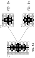
- FIG. 4 a and FIG. 4 b schematically illustrate another example of image distortion phenomenon when enlarging the original image.
- FIG. 5 schematically illustrates a display apparatus according to an embodiment of the present invention.
- FIG. 6 a to FIG. 6 d schematically illustrates an example of reducing the size of an original image according to an embodiment of the present invention.
- FIG. 7 a to FIG. 7 d schematically illustrates another example of reducing the size of an original image according to an embodiment of the present invention.
- FIG. 8 a to FIG. 8 d schematically illustrates an example of enlarging the size of an original image according to an embodiment of the present invention.
- FIG. 9 is a schematic flow chart of an image display method according to an embodiment of the present invention.
- FIG. 5 schematically illustrates a display apparatus according to an embodiment of the present invention.
- the display apparatus 5 has a receiving device 50 , a processing device 51 and a display panel 52 .
- the receiving device 50 receives the original image imported from outside or captured by self of the receiving device 50 .
- the original image includes M number of contiguous image rows.
- the processing device 51 is coupled to the receiving device 50 .
- the display panel 52 has a plurality of contiguous frame periods to display contiguous images. And the display panel 52 displays an output image during each frame period according to the original image.
- the output image is composed of N number of image rows.
- the processing device 51 groups a predetermined number of frame periods into a frame group.
- N numbers of image rows are selected from M number of image rows according to the predetermined image row selecting rule to form an output image.
- the processing device 51 ignores a portion of M number of image rows.
- the processing device 51 repeatedly selecting a portion of M number of image rows.
- each frame group different initial parameters are added to at least two frame periods so as to correspond to different image contents.
- the output images from at least two frame periods are different. Therefore, when reducing (M>N) or when enlarging (M ⁇ N) the size of original image, a plurality of output images are switched during a plurality of contiguous frame periods, with the help of persistence of vision in human vision system, viewer sees a plurality of overlapped output images, therefore user sees less image distortion.
- the processing device 51 groups every two contiguous frame periods into a frame group.
- the original image is represented with L(m), wherein 0 ⁇ m ⁇ M ⁇ 1, for example L(0) represents the first image row of the original image.
- the output image is represented with L′(n,t), 0 ⁇ n ⁇ N ⁇ 1, and t is a time parameter.
- N int[( M ⁇ 1)* s]+ 1
- s is a adjustment parameter.
- the adjustment parameter s>1 means to enlarge the size of the original image; on the contrary, if s ⁇ 1, means to reduce the size of the original image. Therefore it is known that the original image has M number of image rows, and after the original image is enlarged or reduced, the output image will then have N number of image rows.
- the inverse (1/s) of the adjustment parameter s is the selection interval.
- ⁇ (t) represents the initial image row selected according to the frame period
- ⁇ represents a row selecting parameter.
- T represents a frame period
- k is an integer.
- ⁇ (k) is divided into ⁇ (2q) and ⁇ (2q+1) which respectively represents the initial image row selected by the 2q th frame period and the initial image row selected by the (2q+1) th frame period, wherein 0 ⁇ q.
- the output image of the 2q th frame period and the output image of the (2q+1) th frame period have different parameter ⁇ , i.e.
- FIG. 6 b schematically illustrates the output image displayed during the 2q th frame period.
- FIG. 6 c schematically illustrates the output image displayed during the (2q+1) th frame period.
- FIG. 7 b schematically illustrates the output image displayed during the 2q th frame period
- FIG. 7 c schematically illustrates the output image displayed during the (2q+1) th frame period.
- FIG. 8 b schematically illustrates the output image displayed during the 2q th frame period.
- FIG. 8 c schematically illustrates the output image displayed during the (2q+1) th frame period.
- FIG. 9 shows a flow chart of an image display method according to an embodiment of the present invention.
- This flow chart is suitable for a display apparatus.
- ⁇ (2q) is represented with C0
- ⁇ (2q+1) is represented with C1
- an initial parameter Cini is set.
- parameters Ki and Ko are further set, wherein 0 ⁇ Ki ⁇ M ⁇ 1, and 0 ⁇ Ko ⁇ N ⁇ 1. Wherein the parameter Ki tells which image row of the original image is currently selected, and the parameter Ko shows which number of the image row of the output image is.
- the row selection parameter is set to 0.5, means the rounding rule is applied.
- different output images are produced during the 2q th and the (2q+1) th frame periods.
- the output images formed during the 2q th and the (2q+1) th frame periods are mixed according to persistence vision of human vision system, user will see the mix of different images, therefore the enlarged or reduced image is more smooth, the distortion is reduced.
- the line buffer is not necessary to use when enlarge or reduce the image size, therefore the size and the cost of the display apparatus are reduced.
- 5 display apparatus; 50 ⁇ receiving device; 51 ⁇ processing device; 52 ⁇ display panel;
Abstract
Description
N=int[(M−1)*s]+1
L′(n,t)=L(int[n/s+α(t)+ρ])
L′(n,kT)=L(int[n/s+α(k)+ρ]) Formula 2
Claims (15)
Applications Claiming Priority (3)
| Application Number | Priority Date | Filing Date | Title |
|---|---|---|---|
| TW96103502 | 2007-01-31 | ||
| TW096103502A TWI329846B (en) | 2007-01-31 | 2007-01-31 | Method for displaying images and display apparatus using the same |
| TW96103502A | 2007-01-31 |
Publications (2)
| Publication Number | Publication Date |
|---|---|
| US20080211788A1 US20080211788A1 (en) | 2008-09-04 |
| US8026936B2 true US8026936B2 (en) | 2011-09-27 |
Family
ID=39732746
Family Applications (1)
| Application Number | Title | Priority Date | Filing Date |
|---|---|---|---|
| US11/697,098 Expired - Fee Related US8026936B2 (en) | 2007-01-31 | 2007-04-05 | Method for displaying images and display apparatus using the same |
Country Status (2)
| Country | Link |
|---|---|
| US (1) | US8026936B2 (en) |
| TW (1) | TWI329846B (en) |
Cited By (1)
| Publication number | Priority date | Publication date | Assignee | Title |
|---|---|---|---|---|
| US20130022293A1 (en) * | 2011-07-23 | 2013-01-24 | Canon Kabushiki Kaisha | Image processing apparatus, image processing method, and storage medium |
Families Citing this family (1)
| Publication number | Priority date | Publication date | Assignee | Title |
|---|---|---|---|---|
| TWI292893B (en) * | 2005-10-05 | 2008-01-21 | Myson Century Inc | Method for prevention of distorted sub-picture display on flat panel display |
Citations (5)
| Publication number | Priority date | Publication date | Assignee | Title |
|---|---|---|---|---|
| US20040091157A1 (en) * | 2002-10-25 | 2004-05-13 | Kang Jung Yong | Method for resizing an image using the inverse discrete cosine transform |
| US20040126021A1 (en) * | 2000-07-24 | 2004-07-01 | Sanghoon Sull | Rapid production of reduced-size images from compressed video streams |
| US20050024391A1 (en) * | 2003-07-31 | 2005-02-03 | Niranjan Damera-Venkata | Generating and displaying spatially offset sub-frames |
| US20060033761A1 (en) * | 2004-08-12 | 2006-02-16 | Ruei-Shiang Suen | Unique method for performing zoom-in and zoom-out operations with horizontal and vertical video decimation within a wireless device having a video display |
| US7532216B2 (en) * | 2004-12-07 | 2009-05-12 | Micronas Gmbh | Method of scaling a graphic character |
-
2007
- 2007-01-31 TW TW096103502A patent/TWI329846B/en not_active IP Right Cessation
- 2007-04-05 US US11/697,098 patent/US8026936B2/en not_active Expired - Fee Related
Patent Citations (5)
| Publication number | Priority date | Publication date | Assignee | Title |
|---|---|---|---|---|
| US20040126021A1 (en) * | 2000-07-24 | 2004-07-01 | Sanghoon Sull | Rapid production of reduced-size images from compressed video streams |
| US20040091157A1 (en) * | 2002-10-25 | 2004-05-13 | Kang Jung Yong | Method for resizing an image using the inverse discrete cosine transform |
| US20050024391A1 (en) * | 2003-07-31 | 2005-02-03 | Niranjan Damera-Venkata | Generating and displaying spatially offset sub-frames |
| US20060033761A1 (en) * | 2004-08-12 | 2006-02-16 | Ruei-Shiang Suen | Unique method for performing zoom-in and zoom-out operations with horizontal and vertical video decimation within a wireless device having a video display |
| US7532216B2 (en) * | 2004-12-07 | 2009-05-12 | Micronas Gmbh | Method of scaling a graphic character |
Cited By (2)
| Publication number | Priority date | Publication date | Assignee | Title |
|---|---|---|---|---|
| US20130022293A1 (en) * | 2011-07-23 | 2013-01-24 | Canon Kabushiki Kaisha | Image processing apparatus, image processing method, and storage medium |
| US8849066B2 (en) * | 2011-07-23 | 2014-09-30 | Canon Kabushiki Kaisha | Image processing apparatus, image processing method, and storage medium |
Also Published As
| Publication number | Publication date |
|---|---|
| US20080211788A1 (en) | 2008-09-04 |
| TWI329846B (en) | 2010-09-01 |
| TW200832284A (en) | 2008-08-01 |
Similar Documents
| Publication | Publication Date | Title |
|---|---|---|
| JP4306671B2 (en) | Moving image display device and moving image display method | |
| US8988314B2 (en) | Multi-display system | |
| US20080151040A1 (en) | Three-dimensional image display apparatus and method and system for processing three-dimensional image signal | |
| US8860768B2 (en) | Display device and method for driving same | |
| US7463307B2 (en) | Display controlling device capable of displaying multi-windows and related method | |
| US7050113B2 (en) | Digital video data scaler and method | |
| US20110063332A1 (en) | Method and apparatus for over-driving liquid crystal display | |
| US8749713B2 (en) | Video processing apparatus and method | |
| KR20070045949A (en) | Video display device and method for video display | |
| CN102118592A (en) | System for displaying multivideo | |
| KR20110002344A (en) | Image display apparatus and display method of the same | |
| US8593575B2 (en) | Video display apparatus for shortened-delay processing of a video signal and video processing method | |
| TWI694727B (en) | Projection display apparatus and control method | |
| US20080079852A1 (en) | Video display method, video signal processing apparatus, and video display apparatus | |
| US20120256962A1 (en) | Video Processing Apparatus and Method for Extending the Vertical Blanking Interval | |
| US8654206B2 (en) | Apparatus and method for generating high dynamic range image | |
| US8026936B2 (en) | Method for displaying images and display apparatus using the same | |
| JP2007017615A (en) | Image processor, picture processing method, and program | |
| US8570435B2 (en) | Video processing method and device thereof | |
| CN111768732B (en) | Display driving device, display device and display driving method | |
| CN112468756B (en) | Video signal non-lost frame display method and display equipment | |
| JP5259867B2 (en) | Video display device and video processing method | |
| WO2019087984A1 (en) | Image processing device, display device, image processing method, control program, and recording medium | |
| US7940330B2 (en) | Edge adaptive de-interlacing apparatus and method thereof | |
| US20080193036A1 (en) | Method and device for image filtering |
Legal Events
| Date | Code | Title | Description |
|---|---|---|---|
| AS | Assignment |
Owner name: NOVATEK MICROELECTRONICS CORP., TAIWAN Free format text: ASSIGNMENT OF ASSIGNORS INTEREST;ASSIGNOR:TING, HOU-CHUN;REEL/FRAME:019130/0457 Effective date: 20070316 |
|
| ZAAA | Notice of allowance and fees due |
Free format text: ORIGINAL CODE: NOA |
|
| ZAAB | Notice of allowance mailed |
Free format text: ORIGINAL CODE: MN/=. |
|
| STCF | Information on status: patent grant |
Free format text: PATENTED CASE |
|
| FPAY | Fee payment |
Year of fee payment: 4 |
|
| MAFP | Maintenance fee payment |
Free format text: PAYMENT OF MAINTENANCE FEE, 8TH YEAR, LARGE ENTITY (ORIGINAL EVENT CODE: M1552); ENTITY STATUS OF PATENT OWNER: LARGE ENTITY Year of fee payment: 8 |
|
| FEPP | Fee payment procedure |
Free format text: MAINTENANCE FEE REMINDER MAILED (ORIGINAL EVENT CODE: REM.); ENTITY STATUS OF PATENT OWNER: LARGE ENTITY |
|
| LAPS | Lapse for failure to pay maintenance fees |
Free format text: PATENT EXPIRED FOR FAILURE TO PAY MAINTENANCE FEES (ORIGINAL EVENT CODE: EXP.); ENTITY STATUS OF PATENT OWNER: LARGE ENTITY |
|
| STCH | Information on status: patent discontinuation |
Free format text: PATENT EXPIRED DUE TO NONPAYMENT OF MAINTENANCE FEES UNDER 37 CFR 1.362 |
|
| FP | Lapsed due to failure to pay maintenance fee |
Effective date: 20230927 |