US8024099B2 - Deceleration controller for vehicle - Google Patents
Deceleration controller for vehicle Download PDFInfo
- Publication number
- US8024099B2 US8024099B2 US11/591,348 US59134806A US8024099B2 US 8024099 B2 US8024099 B2 US 8024099B2 US 59134806 A US59134806 A US 59134806A US 8024099 B2 US8024099 B2 US 8024099B2
- Authority
- US
- United States
- Prior art keywords
- lateral acceleration
- value
- curve
- vehicle
- limitation value
- Prior art date
- Legal status (The legal status is an assumption and is not a legal conclusion. Google has not performed a legal analysis and makes no representation as to the accuracy of the status listed.)
- Expired - Fee Related, expires
Links
Images


Classifications
-
- B—PERFORMING OPERATIONS; TRANSPORTING
- B60—VEHICLES IN GENERAL
- B60T—VEHICLE BRAKE CONTROL SYSTEMS OR PARTS THEREOF; BRAKE CONTROL SYSTEMS OR PARTS THEREOF, IN GENERAL; ARRANGEMENT OF BRAKING ELEMENTS ON VEHICLES IN GENERAL; PORTABLE DEVICES FOR PREVENTING UNWANTED MOVEMENT OF VEHICLES; VEHICLE MODIFICATIONS TO FACILITATE COOLING OF BRAKES
- B60T8/00—Arrangements for adjusting wheel-braking force to meet varying vehicular or ground-surface conditions, e.g. limiting or varying distribution of braking force
- B60T8/17—Using electrical or electronic regulation means to control braking
- B60T8/1755—Brake regulation specially adapted to control the stability of the vehicle, e.g. taking into account yaw rate or transverse acceleration in a curve
-
- B—PERFORMING OPERATIONS; TRANSPORTING
- B60—VEHICLES IN GENERAL
- B60K—ARRANGEMENT OR MOUNTING OF PROPULSION UNITS OR OF TRANSMISSIONS IN VEHICLES; ARRANGEMENT OR MOUNTING OF PLURAL DIVERSE PRIME-MOVERS IN VEHICLES; AUXILIARY DRIVES FOR VEHICLES; INSTRUMENTATION OR DASHBOARDS FOR VEHICLES; ARRANGEMENTS IN CONNECTION WITH COOLING, AIR INTAKE, GAS EXHAUST OR FUEL SUPPLY OF PROPULSION UNITS IN VEHICLES
- B60K31/00—Vehicle fittings, acting on a single sub-unit only, for automatically controlling vehicle speed, i.e. preventing speed from exceeding an arbitrarily established velocity or maintaining speed at a particular velocity, as selected by the vehicle operator
- B60K31/0066—Vehicle fittings, acting on a single sub-unit only, for automatically controlling vehicle speed, i.e. preventing speed from exceeding an arbitrarily established velocity or maintaining speed at a particular velocity, as selected by the vehicle operator responsive to vehicle path curvature
-
- B—PERFORMING OPERATIONS; TRANSPORTING
- B60—VEHICLES IN GENERAL
- B60T—VEHICLE BRAKE CONTROL SYSTEMS OR PARTS THEREOF; BRAKE CONTROL SYSTEMS OR PARTS THEREOF, IN GENERAL; ARRANGEMENT OF BRAKING ELEMENTS ON VEHICLES IN GENERAL; PORTABLE DEVICES FOR PREVENTING UNWANTED MOVEMENT OF VEHICLES; VEHICLE MODIFICATIONS TO FACILITATE COOLING OF BRAKES
- B60T2201/00—Particular use of vehicle brake systems; Special systems using also the brakes; Special software modules within the brake system controller
- B60T2201/16—Curve braking control, e.g. turn control within ABS control algorithm
-
- B—PERFORMING OPERATIONS; TRANSPORTING
- B60—VEHICLES IN GENERAL
- B60T—VEHICLE BRAKE CONTROL SYSTEMS OR PARTS THEREOF; BRAKE CONTROL SYSTEMS OR PARTS THEREOF, IN GENERAL; ARRANGEMENT OF BRAKING ELEMENTS ON VEHICLES IN GENERAL; PORTABLE DEVICES FOR PREVENTING UNWANTED MOVEMENT OF VEHICLES; VEHICLE MODIFICATIONS TO FACILITATE COOLING OF BRAKES
- B60T2210/00—Detection or estimation of road or environment conditions; Detection or estimation of road shapes
- B60T2210/20—Road shapes
- B60T2210/24—Curve radius
-
- B—PERFORMING OPERATIONS; TRANSPORTING
- B60—VEHICLES IN GENERAL
- B60T—VEHICLE BRAKE CONTROL SYSTEMS OR PARTS THEREOF; BRAKE CONTROL SYSTEMS OR PARTS THEREOF, IN GENERAL; ARRANGEMENT OF BRAKING ELEMENTS ON VEHICLES IN GENERAL; PORTABLE DEVICES FOR PREVENTING UNWANTED MOVEMENT OF VEHICLES; VEHICLE MODIFICATIONS TO FACILITATE COOLING OF BRAKES
- B60T2210/00—Detection or estimation of road or environment conditions; Detection or estimation of road shapes
- B60T2210/30—Environment conditions or position therewithin
- B60T2210/36—Global Positioning System [GPS]
-
- B—PERFORMING OPERATIONS; TRANSPORTING
- B60—VEHICLES IN GENERAL
- B60W—CONJOINT CONTROL OF VEHICLE SUB-UNITS OF DIFFERENT TYPE OR DIFFERENT FUNCTION; CONTROL SYSTEMS SPECIALLY ADAPTED FOR HYBRID VEHICLES; ROAD VEHICLE DRIVE CONTROL SYSTEMS FOR PURPOSES NOT RELATED TO THE CONTROL OF A PARTICULAR SUB-UNIT
- B60W2552/00—Input parameters relating to infrastructure
- B60W2552/20—Road profile, i.e. the change in elevation or curvature of a plurality of continuous road segments
-
- B—PERFORMING OPERATIONS; TRANSPORTING
- B60—VEHICLES IN GENERAL
- B60W—CONJOINT CONTROL OF VEHICLE SUB-UNITS OF DIFFERENT TYPE OR DIFFERENT FUNCTION; CONTROL SYSTEMS SPECIALLY ADAPTED FOR HYBRID VEHICLES; ROAD VEHICLE DRIVE CONTROL SYSTEMS FOR PURPOSES NOT RELATED TO THE CONTROL OF A PARTICULAR SUB-UNIT
- B60W2552/00—Input parameters relating to infrastructure
- B60W2552/30—Road curve radius
Definitions
- the present invention pertains to a deceleration controller for a vehicle, which controller is used for deceleration control of a vehicle when making a curve, for example.
- deceleration controllers for vehicles.
- a safe vehicular speed for making a curve is computed based on a given turning condition of the vehicle and an allowable level of lateral acceleration preset according to a road-surface friction coefficient.
- the speed is automatically reduced to a safe vehicular speed, or lower, by an automatic braking system if the vehicle is about to exceed the safe vehicular speed in order to prevent spinning, drifting and overturning.
- the apparatus comprises a speed sensor for detecting an actual vehicular speed and a controller.
- the controller is operable to set a target vehicular speed calculated based on a given turning condition of the vehicle and a lateral acceleration limitation value.
- the controller is also operable to apply deceleration to the vehicle based on the actual vehicular speed and the target vehicular speed and to correct the deceleration of the vehicle based on information of a curve in a path of the vehicle.
- the apparatus comprises means for detecting an actual vehicular speed, means for setting a target vehicular speed calculated based on a turning condition of the vehicle and a lateral acceleration limitation value, means for applying deceleration to the vehicle based on the actual vehicular speed and the target vehicular speed and means for correcting the deceleration of the vehicle based on information of a curve in a path of the vehicle.
- one method for controlling deceleration of a vehicle comprises detecting a road shape in a path of the vehicle, applying deceleration control to the vehicle when a turning speed of the vehicle is greater than a target vehicular speed and correcting the deceleration control when the road shape is a curve.
- FIG. 1 is a diagram illustrating a deceleration control apparatus for a vehicle in accordance with an embodiment of the invention
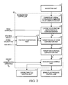
- FIG. 2 is a block diagram illustrating the deceleration control apparatus in accordance with an embodiment of the invention
- FIG. 3 is a flow chart illustrating deceleration control performed in accordance with an embodiment of the invention.
- FIG. 4 is a diagram illustrating the distance L START to the start of a curve, the minimum value R MIN of R, the distance L MIN to the minimum value of the curve, and the distance L END to the end of the curve, which are used for controlling deceleration performed in accordance with an embodiment of the invention;
- FIG. 5 is a block diagram illustrating an example of a yaw rate computation used for controlling deceleration
- FIG. 6 is a flow chart illustrating the corrective lateral acceleration limitation value computation performed in accordance with an embodiment of the invention.
- FIG. 7 is a graph illustrating a first application example of the relationship between value R and a correction coefficient K D ;
- FIG. 8 is a graph illustrating a first application example of the relationship between a correction coefficient K D and a reference lateral acceleration limitation value Ygc_ 0 ;
- FIG. 9 is a diagram illustrating whether a reference lateral acceleration limitation value can be set in accordance with an embodiment of the invention.
- FIG. 10 is a graph illustrating the relationship between distance L START to the start of a curve and a corrective lateral acceleration limitation value Ygc_HO;
- FIG. 11 is a graph illustrating a first application example of the relationship between distance L END to the end of a curve and a corrective lateral acceleration limitation value Ygc_HO;
- FIG. 12 is a graph illustrating the relationship between traveling position along a curve and a corrective lateral acceleration limitation value Ygc_HO;
- FIG. 13 is a graph illustrating the relationship between vehicular speed and a velocity-sensitive lateral acceleration correction value Ygv;
- FIG. 14 is a graph illustrating the relationship between the accelerator opening and an accelerator-sensitive lateral acceleration correction value Yga;
- FIG. 15 is a diagram illustrating the input/output of data at a target vehicular speed computed in accordance with an embodiment of the invention.
- FIG. 16 is a flow chart illustrating the control signal output during the deceleration control performed in accordance with an embodiment of the invention.
- FIG. 17 is a graph illustrating a second application example of the relationship between value R and correction coefficient K D ;
- FIG. 18 is a graph illustrating another relationship between value R and correction coefficient K D in accordance with an embodiment of the invention.
- FIG. 19 is a graph illustrating the relationship between an overspeed amount and a correction coefficient K D in accordance with an embodiment of the invention.
- FIG. 20 is a graph illustrating the relationship between an overspeed amount and a reference lateral acceleration limitation value Ygc_ 0 ;
- FIG. 21 is a graph illustrating the relationship between a predicted lateral acceleration value Yg_est and a correction coefficient K D ;
- FIG. 22 is a graph illustrating the relationship between a predicted lateral acceleration value Yg_est and a reference lateral acceleration limitation value Ygc_ 0 ;
- FIG. 23 is a graph illustrating a first application example of the relationship among value R, an overspeed amount, and a correction coefficient K D ;
- FIG. 24 is a graph illustrating a second application example of the relationship among value R, an overspeed amount, and a correction coefficient K D ;
- FIG. 25 is a graph illustrating a third application example of the relationship among value R, an overspeed amount, and a correction coefficient K D ;
- FIG. 26 is a graph illustrating a second application example of the relationship between a correction coefficient K D and a reference lateral acceleration limitation value Ygc_ 0 ;
- FIG. 27 is a graph illustrating a third application example of the relationship between a correction coefficient K D and a reference lateral acceleration limitation value Ygc_ 0 ;
- FIG. 28 is a graph illustrating a second application example of the relationship between distance L END to the end of a curve and a corrective lateral acceleration limitation value Ygc_HO;
- FIG. 29 is a graph illustrating a third application example of the relationship between distance L END to the end of a curve and a corrective lateral acceleration limitation value Ygc_HO;
- FIG. 30 is a diagram illustrating the cancellation of a correction made to a lateral acceleration limitation value Yg* in response to an accelerator operation performed by a driver of the vehicle.
- FIG. 31 is a flow chart illustrating the process of canceling a correction made to the lateral acceleration limitation value Yg* based on the correction coefficient K D in response to an accelerator operation performed by a driver on the vehicle.
- the deceleration control may be applied for conditions other than traveling along a curve, such as when changing lanes. This can cause a sense of discomfort in the driver if the deceleration control is applied unnecessarily during travel other than along a curve.
- a target vehicular speed is set based on a given turning condition of the vehicle and a preset lateral acceleration limitation value. Deceleration control is performed based on the target vehicular speed and the current vehicular speed.
- the vehicle deceleration control apparatus detects information on the curve along which the vehicle travels and makes a correction to reduce the lateral acceleration limitation value based on the curve information. A correction is made to reduce the lateral acceleration limitation value when traveling along a curve, so that deceleration control can be applied more easily when traveling along a curve than when traveling straight ahead, and deceleration control suitable for a given road shape can be realized. As a result, the deceleration control apparatus can perform deceleration control appropriate for a given road shape.
- FIG. 1 is a diagram illustrating an embodiment of a vehicle deceleration control apparatus being applied to an outline configuration of a vehicle.
- a brake fluid pressure control unit 1 is configured to control brake fluid supplied to respective wheel cylinders, not shown, for respective wheels 2 FL, 2 FR, 2 RL, and 2 RR. That is, brake fluid boosted by a master cylinder is supplied to respective wheel cylinders according to the degree of pressing of a brake pedal by a driver.
- the pressure of the brake fluid supplied to the respective wheel cylinders is controlled by brake fluid pressure control unit 1 , which is provided between the master cylinder and the respective wheel cylinders, independently of an operation imparted to the brake pedal.
- the brake fluid pressure control unit 1 utilizes a brake fluid pressure control circuit for antiskid control and traction control.
- the brake fluid pressure control unit 1 controls the brake fluid pressure in the respective wheel cylinders according to the value of a brake fluid pressure instruction value from a deceleration controller 10 to be described hereafter.
- the vehicle is provided with engine throttle control unit 3 capable of controlling the throttle opening of a throttle valve (not shown).
- the engine throttle control unit 3 is configured in such a manner that while it is capable of controlling the throttle opening angle by itself, when a throttle opening command value is input from the deceleration controller 10 the engine throttle control unit 3 controls the throttle opening angle according to the throttle opening command value.
- the vehicle is provided with navigation unit 4 , which obtains information regarding the road shape ahead of the vehicle.
- the navigation unit 4 outputs the information obtained regarding the road shape ahead of the vehicle to deceleration controller 10 .
- a yaw rate sensor 11 detects a yaw rate ⁇ ′ (referred to as measured yaw rate ⁇ ′ hereinafter) of the vehicle.
- a steering angle sensor 12 detects steering angle ⁇ of the steering wheel and outputs the signal to the deceleration controller 10 .
- An accelerator sensor 14 detects depression amount (e.g., opening angle ⁇ th ) of an accelerator, not shown, and outputs the signal to the deceleration controller 10 .
- a second acceleration sensor 15 detects lateral acceleration Yg generated by the vehicle and outputs the signal to the deceleration controller 10 .
- the deceleration controller 10 is equipped with a yaw rate computation part 21 , which computes a selected yaw rate ⁇ * to be used for arithmetic processing based on the steering angle ⁇ sent from the steering angle sensor 12 , the vehicle velocities Vw FL through Vw RR sent from the speed sensors 13 FL through 13 RR, and the measured yaw rate ⁇ ′ sent from the yaw rate sensor 11 .
- the deceleration controller 10 also includes a lateral acceleration limitation value computation part 26 , which computes lateral acceleration limitation value Yg*, and a corrective lateral acceleration limitation value computation part 25 , which corrects the corrective lateral acceleration value Yg* computed by the lateral acceleration limitation value computation part 26 .
- a target vehicular speed computation part 22 of the deceleration controller 10 computes target vehicular speed V* based on the selected yaw rate ⁇ * from the yaw rate computation part 21 , the lateral acceleration limitation value Yg* computed by lateral acceleration limitation value computation part 26 , and a road-surface friction coefficient ⁇ .
- a target deceleration computation part 23 of the deceleration controller 10 computes target deceleration Xg* based on target vehicular speed V*, which is computed by the target vehicular speed computation part 22 .
- the deceleration controller 10 includes a deceleration control part 24 , which drives the brake fluid pressure control unit 1 and the engine throttle control unit 3 so as to realize the target deceleration Xg* computed by the target deceleration computation part 23 .
- the flow chart of FIG. 3 shows the deceleration control process executed by the deceleration controller 10 .
- the deceleration controller can be any controller, for example, a standard engine microcontroller that includes a central processing unit (CPU), random access memory (RAM), read only memory (ROM) and input/output ports receiving input signals and sending the command signal as discussed in more detail below.
- the processing parts (e.g., programming instructions) described herein are generally stored in memory, and the functions of each of the parts is performed by the logic of the CPU.
- the controller that performs the functions of each of the parts described herein could also be part of a dedicated microcontroller or could be a microprocessor using external memory.
- the deceleration control process is executed in the form of timer interrupt process at prescribed intervals.
- step (denoted as S hereafter) 1 the road shape, in particular a curve, is detected by navigation unit 4 shown in FIG. 1 .
- Navigation unit 4 detects the curve ahead, in the direction of vehicle travel, based on information regarding the road shape ahead of the vehicle. More specifically, the radius value R of the curve is computed using a three-point method involving nodes, linkage relationship among the nodes, road type, and link type in order to detect the road shape.
- the radius value R may be embedded in the navigation system or the nodes.
- navigation unit 4 computes distance L START to the start of the curve (the node corresponding to the start of the curve), minimum value R MIN of value R of the curve, distance L MIN to the curve minimum value (the node corresponding to minimum value R MIN ), distance L END to the end of the curve (the node corresponding to the end of the curve), and curve direction R dir based on the node information. Navigation unit 4 then outputs the above computed values to corrective lateral acceleration limitation value computation part 25 .
- a yaw rate is computed. Computation of the yaw rate is carried out by yaw rate computation part 21 shown in FIG. 2 . As illustrated in FIG. 5 , yaw rate computation part 21 is equipped with yaw rate estimation part 31 and yaw rate selection part 32 . Yaw rate estimation part 31 estimates a yaw rate ⁇ e based on steering angle ⁇ detected by steering angle sensor 12 and wheel velocities Vw detected by wheel speed sensors 13 . The estimated yaw rate ⁇ e is estimated using a widely used technique based on the steering angle ⁇ and the vehicular speed or wheel velocity.
- Yaw rate estimation part 31 outputs the estimated yaw rate ⁇ e (referred as estimated yaw rate ⁇ e hereinafter) to yaw rate selection part 32 .
- Yaw rate selection part 32 performs select-high by selecting the higher value between the estimated yaw rate ⁇ e input from yaw rate estimation part 31 and the measured yaw rate ⁇ ′ detected by yaw rate sensor 11 .
- the estimated yaw rate ⁇ e calculated from the steering angle can be obtained more quickly than the measured yaw rate ⁇ ′ detected by yaw rate sensor 11 .
- a case may occur in which the vehicle behavior changes in a direction such that the measured yaw rate ⁇ ′ increases without much turning of the steering wheel while traveling on a road with a low friction coefficient, for example, in the case of a slow spin mode.
- the select-high between the estimated yaw rate ⁇ e and the measured yaw rate ⁇ ′ is performed to allow selection of the measured yaw rate ⁇ ′ when applicable, whereby when the measured yaw rate ⁇ ′ is higher, the measured yaw rate ⁇ ′ is selected for prompt engagement of deceleration control.
- Yaw rate selection part 32 outputs the value selected through select-high as selected yaw rate value ⁇ * (>0).
- a corrective lateral acceleration limitation value is computed by corrective lateral acceleration limitation value computation part 25 shown in FIG. 2 according to the execution illustrated in the flow chart of FIG. 6 .
- correction coefficient K D is computed. More specifically, as shown in FIG. 7 , correction coefficient K D is computed based on value R output by navigation unit 4 in S 1 , wherein correction coefficient K D increases as value R decreases. Value R used for the computation of correction coefficient K D is value R of minimum value R MIN of the curve. As shown in FIG. 7 , the correction coefficient K D is set in the range of 0-100.
- correction coefficient K D is set when curve value R is lower than upper limit value R 2 , for example, 300R. That is, correction coefficient K D is set within maximum value R 2 .
- a reference lateral acceleration limitation value Ygc_ 0 which is used for computing a corrective lateral acceleration limitation value Ygc_HO in S 23 , to be described later, is set.
- the reference lateral acceleration limitation value Ygc_ 0 is computed based on correction coefficient K D computed in S 21 .
- reference lateral acceleration limitation value Ygc_ 0 is set at a higher value, with the provision that prescribed value Ygc is the upper limit, as correction coefficient K D decreases.
- reference lateral acceleration limitation value Ygc_ 0 is set at a value lower than prescribed value Ygc (Ygc_ 0 ⁇ Ygc).
- the reference lateral acceleration limitation value Ygc_ 0 is set at prescribed value Ygc (the value when correction coefficient K D is 0).
- the prescribed value Ygc is 0.45 g.
- reference lateral acceleration limitation value Ygc_ 0 can be set is determined based on the direction of the steering wheel. As shown in FIG. 9 , setting of reference lateral acceleration limitation value Ygc_ 0 is disabled when curve direction R dir output from navigation unit 4 does not match the steering wheel direction (i.e., the direction turned by the driver) in S 1 , and setting of reference lateral acceleration limitation value Ygc_ 0 is enabled when curve direction R dir output from navigation unit 4 matches the steering wheel direction. Then, as illustrated in FIG. 8 , when setting of the reference lateral acceleration limitation value Ygc_ 0 is enabled, the reference lateral acceleration limitation value Ygc_ 0 is set based on correction coefficient K D . When setting of the reference lateral acceleration limitation value Ygc_ 0 is disabled (i.e., when setting is prohibited), the reference lateral acceleration limitation value Ygc_ 0 is set at the prescribed value Ygc.
- corrective lateral acceleration limitation value Ygc_HO which is used to correct lateral acceleration limitation value Yg to be described later, is computed.
- L S1 prescribed value that is, when the vehicle is traveling, before reaching the position at prescribed distance L S1 from the start of the curve
- corrective lateral acceleration limitation value Ygc_HO is set at prescribed value Ygc.
- corrective lateral acceleration limitation value Ygc_HO is brought increasingly closer to reference lateral acceleration limitation value Ygc_ 0 , which was set based on correction coefficient K D in S 22 .
- corrective lateral acceleration limitation value Ygc_HO is set at reference lateral acceleration limitation value Ygc_ 0 , which was set based on correction coefficient K D in S 22 .
- Ygc_HO ( Ygc ⁇ Ygc — 0)/ L S1 ⁇ L START +Ygc — 0 (2)
- Reference lateral acceleration limitation value Ygc_ 0 decreases as correction coefficient K D increases (as value R decreases), referring to S 22 , and the corrective lateral acceleration limitation value Ygc_HO, which is set using the reference lateral acceleration limitation value Ygc_ 0 , decreases as correction coefficient K D increases (as value R decreases) when L START ⁇ L S1 or L START ⁇ 0.
- corrective lateral acceleration limitation value Ygc_HO which is used for ending correction of the lateral acceleration limitation value, is set.
- corrective lateral acceleration limitation value Ygc_HO changes, as shown in FIG. 12 , for the section proceeding prescribed value L S1 before the start of the curve (the point that corresponds to L START ), the section of prescribed value L S1 , the section between the start of the curve (the point that corresponds to L START ) and the end of the curve (the point that corresponds to L END ), and the section after the end of the curve (a point after L END ).
- Corrective lateral acceleration limitation value Ygc_HO is set according to the position where the vehicle is traveling with respect to the curve.
- lateral acceleration limitation value Yg* is set based on corrective lateral acceleration limitation value Ygc_HO, it can be said that lateral acceleration limitation value Yg* is set according to a given position of vehicle travel with respect to the curve.
- correction coefficient K D is computed based on value R of the curve (in S 21 of FIG. 6 )
- reference lateral acceleration limitation value Ygc_ 0 is computed based on the computed correction coefficient K D (in S 22 of FIG. 6 )
- corrective lateral acceleration limitation value Ygc_HO is computed using the computed reference lateral acceleration limitation value Ygc_ 0 (in S 23 of FIG. 6 ).
- Prescribed value L S1 may be replaced by time.
- L START 0
- corrective lateral acceleration limitation value Ygc_HO is gradually brought closer to reference lateral acceleration limitation value Ygc_ 0 , which was set based on correction coefficient K D in S 22 , until the vehicle reaches the start of the curve.
- lateral acceleration limitation value Yg* is computed. The computation is carried out by lateral acceleration limitation value computation part 26 .
- Lateral acceleration limitation value Yg* is a value for limiting target lateral acceleration for stable travel of the vehicle while on the curve.
- velocity-sensitive lateral acceleration correction value Ygv decreases as vehicular speed V increases.
- accelerator-sensitive lateral acceleration correction value Yga increases as the accelerator opening angle increases.
- accelerator-sensitive lateral acceleration correction value Yga takes a fixed value. Therefore, the accelerator-sensitive lateral acceleration correction value Yga increases as the accelerator opening angle increases.
- target vehicular speed V* is computed.
- the computation is carried out by target vehicular speed computation part 22 shown in FIG. 2 .
- the target vehicular speed is calculated based on road-surface friction coefficient (estimated value) ⁇ , lateral acceleration limitation value Yg* and selected yaw rate ⁇ * as shown in FIG. 15 .
- target vehicular speed V* is reduced as road-surface friction coefficient ⁇ decreases
- target vehicular speed V* is reduced as lateral acceleration limitation value Yg* decreases
- target vehicular speed V* is reduced as selected yaw rate ⁇ * increases.
- target deceleration Xg* is computed.
- the computation is carried out by target deceleration computation part 23 shown in FIG. 2 .
- target deceleration can be computed promptly to reduce the speed promptly, when the steering wheel is operated quickly deceleration can be applied quickly.
- control signal output processing is carried out, whereby control signals are output to control engine throttle control unit 3 and brake fluid pressure control unit 1 to match the actual deceleration with target deceleration Xg* computed in S 6 .
- the deceleration control process is carried out by deceleration control part 24 of the deceleration controller 10 shown in FIG. 2 as shown in the deceleration control process illustrated in the flow chart of FIG. 16 .
- S 32 it is determined whether target deceleration Xg* is positive.
- Xg*>0 that is, when target deceleration Xg* is a value that requires deceleration
- S 33 a transition is made to S 33 .
- Xg* ⁇ 0 that is, when target deceleration Xg* is a value that requires acceleration
- the initial value of the target throttle opening angle is base throttle opening angle Acc_bs read in S 31 .
- the vehicular speed is reduced through throttle control, that is, the throttle opening angle is reduced from a given throttle opening angle, which corresponds to the amount the accelerator is operated by the driver by prescribed value ⁇ Adn at each sampling when target deceleration Xg* is positive.
- the throttle control by engine throttle control unit 3 in S 34 through S 36 and the braking control in S 37 are carried out in order to attain target deceleration Xg*.
- base throttle opening Acc_bs is set as target throttle opening angle Acc, and the timer interrupt process is ended without involving deceleration control before returning to the main program.
- S 40 braking control is applied.
- the brakes are controlled by reducing the brake fluid pressure using brake fluid pressure control unit 1 .
- timer interrupt processing is ended immediately, and the process returns to a prescribed main program in order to continue with throttle recovery.
- target deceleration Xg* is equal to or lower than 0 (Xg* ⁇ 0).
- a transition is made to S 38 according to the decision made in S 32 .
- target throttle Acc is set at base throttle opening angle Acc_bs that corresponds to the acceleration operation amount performed by the driver.
- deceleration control does not get involved, and the vehicle continues to travel according to accelerator operation performed by the driver.
- deceleration control can be applied without subjecting the driver to a sense of discomfort by reducing throttle opening angle ⁇ Adn gradually.
- lateral acceleration control value Yg* is computed based on the corrective lateral acceleration limitation value Ygc_HO (in S 4 of FIG. 3 )
- target lateral acceleration V* and target deceleration Xg* are computed based on the lateral acceleration control value Yg* (in S 5 and S 6 of FIG. 3 ) so that the timing of the involvement of braking control changes according to the travel position of the vehicle with respect to the curve.
- target deceleration Xg* When target deceleration Xg* is greater than 0, deceleration control will be implemented. Because target deceleration Xg* increases as target vehicular speed V* is reduced, the timing of involvement of deceleration control is set forward (refer to equation (6)). In addition, because target vehicular speed V* is reduced as lateral acceleration limitation value Yg* decreases (refer to equation (5)), deceleration control intervention timing is set forward as lateral acceleration limitation value Yg* decreases.
- lateral acceleration limitation value Yg* decreases as corrective lateral acceleration limitation value Ygc_HO decreases (refer to equation (4))
- deceleration control intervention timing is set forward as corrective lateral acceleration limitation value Ygc_HO decreases.
- deceleration control intervention timing is set forward as reference lateral acceleration limitation value Ygc_ 0 decreases.
- deceleration control intervention timing is set forward as correction coefficient K D increases. Then, correction coefficient K D increases as curve value R decreases (refer to S 22 of FIG. 6 ), and the deceleration control intervention timing is set forward as curve value R decreases.
- the forwarded deceleration control intervention timing also means that cancellation of deceleration control becomes more difficult, and thus easier to maintain. The relationship is summarized below in Table 1:
- Deceleration Control Intervention Timing is Set Forward (i.e. when cancellation of deceleration control becomes more difficult)
- Target deceleration Xg* High Target vehicular speed: V* Low Lateral speed limitation value: Yg* Low Corrective lateral acceleration limitation value: Ygc_HO Low Reference lateral acceleration limitation value: Ygc_0 Low Correction coefficient: K D High Value R Low
- lateral speed limitation value Yg* (and accordingly the corrective lateral acceleration limitation value Ygc_HO) is set based on value R at a prescribed position within the curve, and lateral speed limitation value Yg* decreases as value R of the curve ahead of the vehicle decreases.
- deceleration control can be implemented more easily based on value R of the curve.
- Reference lateral acceleration limitation value Ygc_ 0 is set based on value R.
- the value R is a value computed by navigation unit 4 based on information regarding the road shape ahead of the vehicle available from, for example, nodes. Information regarding the road shape ahead of the vehicle obtained by navigation unit 4 may sometimes contain an error.
- GPS Global Positioning System
- a map error for example a change in the way nodes are assigned
- value R computed based on the road shape information ahead of the vehicle may contain an error.
- deceleration control may be involved if the driver manipulates the steering wheel, because the estimated yaw rate ⁇ e is estimated based on steering angle ⁇ detected by steering angle sensor 12 in S 2 , the track of the vehicle steered by the driver represents the actual road shape.
- Corrective lateral acceleration limitation value Ygc_HO is brought gradually closer to reference lateral acceleration limitation value Ygc_ 0 by gradually increasing the amount of correction of lateral speed limitation value Yg* to gradually reflect corrective lateral acceleration limitation value Ygc_HO upon lateral speed limitation value Yg* in order to prevent an influence of an error in the road shape information ahead of the vehicle on lateral speed limitation value Yg* and to apply deceleration control while reflecting the steering condition manipulated by the driver according to the actual road shape.
- Whether a reference lateral acceleration limitation value can be set is determined according to the steering direction (refer to FIG. 9 ).
- the setting of a reference lateral acceleration limitation value is disabled when curve direction R dir does not match the steering direction (i.e., the direction steered by the driver).
- the setting is enabled when curve direction R dir matches the steering direction.
- the reference lateral acceleration limitation value Ygc_ 0 can be set only when curve direction R dir matches the steering direction in order to prevent correction of lateral speed limitation value Yg* by mistake when traveling in a scenario involving a curve that does not require a correction.
- Correction coefficient K D is computed based on minimum value R MIN of value R at the curve (refer to S 21 in FIG. 6 ). As a result, because the deceleration control intervention timing is set forward as value R decreases (refer to Table 1), the speed can be reduced well before the value R reaches minimum value R MIN so that the speed of the vehicle can be reduced effectively through deceleration control.
- Correction coefficient K D is set when curve value R is lower than prescribed upper limit value R 2 (for example, 300R); that is, correction coefficient K D is set within upper limit value R 2 (refer to S 21 in FIG. 6 ).
- R 2 for example, 300R
- correction coefficient K D is set within upper limit value R 2 (refer to S 21 in FIG. 6 ).
- Value R is computed from multiple coordinates (nodes) in the case of a three-point or five-point method (or N-point method). Therefore, the accuracy of the computation of value R is improved as more nodes (coordinates) are used for the computation.
- a road shape involving many nodes represents a case in which R is low, and the accuracy of the computation of value R is degraded as R increases.
- Velocity-sensitive lateral acceleration correction value Ygv increases as vehicular speed V decreases (refer to FIG. 13 ). Therefore, the lateral acceleration limitation value Yg* also increases (refer to equation (4)).
- Target vehicular speed V* is increased in a low-speed area (refer to equation (5)), so that deceleration control becomes harder to apply (refer to equation (6)). The application of deceleration control is made harder while in a low-speed area to reduce driver discomfort from deceleration control being applied while in the low-speed area.
- Accelerator-sensitive lateral acceleration correction value Yga increases as the accelerator opening angle is increased (refer to FIG. 14 ). Therefore, lateral acceleration limitation value Yg* also increases (refer to equation (4)).
- Target vehicular speed V* is increased as the accelerator opening angle is increased (refer to equation (5)), and the application of deceleration control becomes harder (refer to equation (6)). The application of deceleration control is made harder when the accelerator opening angle is increased in order to prevent creation of a sense of slowdown in the driver as the driver performs an acceleration operation when recovering from a corner.
- correction coefficient K D is set at a fixed value (for example, 100R) regardless of value R when lower than R 1 ( ⁇ R 2 ).
- correction coefficient K D is set only when value R is low.
- correction coefficient K D When correction coefficient K D is high, the deceleration intervention timing is set forward, or application of deceleration control is facilitated.
- correction coefficient K D When correction coefficient K D is high, the correction coefficient K D is computed based on a highly accurate value R (low value R).
- correction coefficient K D When correction coefficient K D is set at a higher value in an area where value R is low, deceleration control can be applied promptly based on a highly accurate value R, that is, a highly accurate estimation of the road shape.
- Correction coefficient K D may be set based on the amount of overspeed. For example, as shown in FIG. 19 , correction coefficient K D is increased as the amount of overspeed increases, and correction coefficient K D is set at a fixed value once the amount of overspeed has exceeded a certain value.
- the amount of overspeed refers to the differential value between prescribed vehicular speed V* 2 and the current vehicular speed Vi, which is calculated with Vi ⁇ V* 2 as a condition.
- reference lateral acceleration limitation value Ygc_ 0 is set lower as correction coefficient K D increases.
- the reference lateral acceleration limitation value Ygc_ 0 is set at a higher value provided that reference lateral acceleration limitation value Ygc is the upper limit.
- Reference lateral acceleration limitation value Ygc_ 0 decreases as the amount of overspeed increases, so that the deceleration control intervention timing is set forward.
- Correction coefficient K D may be set based on an estimated lateral acceleration value.
- correction coefficient K D is increased as computed estimated lateral acceleration value Yg_est increases.
- Correction coefficient K D is set at a fixed value when estimated lateral acceleration value Yg_est is higher than a certain value.
- the reference lateral acceleration limitation value Ygc_ 0 is set at a lower value as correction coefficient K D increases.
- reference lateral acceleration limitation value Ygc_ 0 is set at a higher value provided that reference lateral acceleration limitation value Ygc is the upper limit. Because reference lateral acceleration limitation value Ygc_ 0 decreases as estimated lateral acceleration value Yg_est increases, the deceleration control intervention timing is set forward.
- Correction coefficient K D may be set based on value R and the amount of overspeed. For example, as shown in FIG. 23 through FIG. 25 , correction coefficient K D is set to a higher value as value R decreases, and correction coefficient K D is set at a higher value as the amount of overspeed increases while using the amount of overspeed as a parameter. When value R is high (provided that value R is lower than R 2 ), and the amount of overspeed is large, the correction coefficient K D can be set at a corresponding high value. Even if value R is low, if the amount of overspeed is large the correction coefficient K D can be set at a high value.
- correction coefficient K D obtained based on value R and correction coefficient K D obtained based on the amount of overspeed may be selected, and the higher value may be set as the final correction coefficient K D .
- a specific relationship between correction coefficient K D and reference lateral acceleration limitation value Ygc_ 0 exists according to a first application example.
- the reference lateral acceleration limitation value Ygc_ 0 decreases as correction coefficient K D increases.
- Reference lateral acceleration limitation value Ygc_ 0 is set at a fixed value (fixed at a low value) regardless of correction coefficient K D when correction coefficient K D is equal to or higher than prescribed value K D 1 . Therefore, a minimum value is provided for reference lateral acceleration limitation value Ygc_ 0 .
- the deceleration control intervention timing is set further forward as reference lateral acceleration limitation value Ygc_ 0 decreases (refer to Table 1).
- a minimum value is provided for reference lateral acceleration limitation value Ygc_ 0 to prevent lateral speed limitation value Yg* from reaching a prescribed minimum value in order to prevent the deceleration control intervention timing from going forward more than necessary, which in turn prevents the creation of a sense of discomfort in the driver during deceleration control.
- reference lateral acceleration limitation value Ygc_ 0 is set at a higher value as correction coefficient K D decreases
- reference lateral acceleration limitation value Ygc_ 0 is set at a fixed value (e.g., fixed at a high value) regardless of correction coefficient K D if correction coefficient K D is equal to or lower than prescribed value K D 2 .
- a dead zone where reference lateral acceleration limitation value Ygc_ 0 does not change in response to correction coefficient K D is provided.
- application of deceleration control can be prevented when deceleration is not needed, such as in an area where value R is high or in an area where the amount of overspeed is small. This is especially effective in an area where value R is high because the computation accuracy of the value R there may be degraded.
- a specific setting of corrective lateral acceleration limitation value Ygc_HO is used for ending correction of the lateral acceleration limitation value.
- the corrective lateral acceleration limitation value Ygc_HO is changed from reference lateral acceleration limitation value Ygc_ 0 toward the prescribed value Ygc at a prescribed slope as the value decreases, that is, according to the distance from the curve after the vehicle has moved beyond the end of the curve.
- the correction of the lateral acceleration limitation value is canceled gradually after the vehicle has moved beyond the end of the curve.
- the sense of slowdown that is created in the driver by the deceleration control can be reduced after passing the end of the curve. Furthermore, because correction of the lateral acceleration limitation value is canceled gradually instead of canceling the correction of the lateral acceleration limitation value at once, deceleration control can be maintained under a condition in which it can be applied promptly while reducing the sense of slowdown created in the driver by the deceleration control.
- corrective lateral acceleration limitation value Ygc_ 0 or lateral acceleration limitation value Yg* begins to increase before the end of the curve, cancellation of deceleration control becomes easier so that creation of a sense of drag in the driver can be prevented during deceleration control.
- a revision of lateral acceleration limitation value Yg* based on correction coefficient K D may be canceled when a driving operation is performed by the driver.
- the target vehicular speed V* ( Vc_HO) computed using corrective lateral acceleration limitation value Ygc_HO (Ygc>Ygc_HO ⁇ Ygc_ 0 ), which is computed based on correction coefficient K D , is slower than the actual vehicular speed Vi (V).
- the reference lateral acceleration limitation value Ygc is not corrected based on correction coefficient K D although deceleration control is actually applied (Vi>Vc_HO, ⁇ V ⁇ 0). The result is that the target vehicular speed is greater than the actually vehicular speed, Vc>Vi (Xg* ⁇ 0).
- Vc>Vi (Xg* ⁇ 0) the target vehicular speed is greater than the actually vehicular speed
- Xg* ⁇ 0 the target vehicular speed
- the driver operates the accelerator, accelerating the vehicle, and deceleration control is not applied (the area sandwiched by the dotted lines in FIG. 30 )
- correction of lateral speed limitation value Yg* based on correction coefficient K D is canceled. This occurs, for example, at the end of the curve.
- FIG. 31 shows processing for canceling the correction of lateral speed limitation value Yg* based on correction coefficient K D .
- S 51 it is determined whether the current vehicular speed Vi is slower than the target vehicular speed Vc, whether the current vehicular speed Vi is faster than the target vehicular speed Vc_HO, and whether the accelerator opening angle ⁇ th is greater than 5%.
- Processing advances to S 52 when the conditions are met (Vc>Vi>Vc_HO and ⁇ th >5%), or advances to S 53 when the conditions are not met.
- deceleration control When the accelerator is operated by the driver while deceleration control is in progress, the correction of lateral acceleration limitation value Yg based on correction coefficient K D is canceled, and deceleration control can be applied in conformity with the intent of the driver. For example, even if deceleration control is applied unnecessarily due to a drop in the detection accuracy of the road shape, that is, value R, deceleration control is canceled when the driver accelerates, so that creation of a sense of discomfort in the driver by the deceleration control can be prevented.
- correction coefficient K D is obtained using value R of the curve in the first application embodiment
- the corrective lateral acceleration limitation value may be set at a prescribed value (for example, 0.35 G) during the period between the start and the end of the curve without using curve value R.
- the information about the curve ahead is detected in advance so as to correct the lateral acceleration limitation value to be used when the vehicle is traveling along the curve (S 1 in FIG. 3 ), whether the road shape at the current traveling position indicates a curve may be detected in real-time in order to correct the lateral acceleration limitation value at the current position based on the result of the detection.
- deceleration control is facilitated when traveling along a curve by correcting the lateral acceleration limitation value.
- the application of deceleration control may be facilitated when traveling along a curve by correcting the target vehicular speed and the deceleration control timing based on correction coefficient K D in S 22 and S 23 in FIG. 6 .
- the target vehicular speed computation part 22 of deceleration controller 10 is used to realize a target vehicular speed setting means that sets the target vehicular speed based on the turning condition of the vehicle and a preset lateral acceleration limitation value
- the wheel speed sensors 13 FL through 13 RR are used to realize a speed detection means
- the navigation unit 4 is used to realize a curve detection means that detects information on the curve along which the vehicle travels
- the corrective lateral acceleration limitation value computation part 25 is used to realize a lateral acceleration limitation value computation means that makes a correction so as to reduce the lateral acceleration limitation value when the vehicle is traveling along the curve.
Landscapes
- Engineering & Computer Science (AREA)
- Transportation (AREA)
- Mechanical Engineering (AREA)
- Chemical & Material Sciences (AREA)
- Combustion & Propulsion (AREA)
- Control Of Driving Devices And Active Controlling Of Vehicle (AREA)
- Regulating Braking Force (AREA)
- Control Of Vehicle Engines Or Engines For Specific Uses (AREA)
- Electrical Control Of Air Or Fuel Supplied To Internal-Combustion Engine (AREA)
Abstract
Description
Ygc — HO=Ygc (1)
Ygc — HO=(Ygc−Ygc —0)/L S1 ×L START +Ygc —0 (2)
Ygc — HO=Ygc —0 (3)
Yg*=Ygc — HO+Ygv+Yga (4)
where Ygc_HO is the corrective lateral acceleration limitation value computed in S3, Ygv is a velocity-sensitive lateral acceleration correction value (a corrective value set according to the vehicular speed), and Yga is an accelerator-sensitive lateral acceleration correction value (a corrective value set according to the accelerator opening angle).
V*=μ×Yg*/φ* (5)
Xg*=K×ΔV/Δt (6)
where ΔV indicates the value of the difference (speed deviation value) between vehicular speed V and target vehicular speed V* computed in S5 (ΔV=V−V*), Δt indicates a prescribed time (time required to zero-out the speed deviation value), and K indicates a prescribed gain.
Xg*=(K1×ΔV+K2×dΔV)/Δt (7)
where dΔV indicates the deviation value obtained by subtracting a past value ΔVz of speed deviation ΔV from the current speed deviation ΔV(dΔV=ΔV−ΔVz), and K1 and K2 are prescribed gains.
Acc=Acc−ΔAdn (8)
Acc=Acc — bs (9)
Acc=Acc+ΔAup (10)
Hence, the throttle is recovered by increasing the throttle opening angle by prescribed value ΔAup at each sampling.
| Deceleration Control Intervention Timing is Set Forward |
| (i.e. when cancellation of deceleration |
| control becomes more difficult) |
| Target deceleration: Xg* | High |
| Target vehicular speed: V* | Low |
| Lateral speed limitation value: Yg* | Low |
| Corrective lateral acceleration limitation value: Ygc_HO | Low |
| Reference lateral acceleration limitation value: Ygc_0 | Low |
| Correction coefficient: KD | High |
| Value R | Low |
V* 2=√(Ygc×R) (11)
where R represents curve value R corresponding to the given road shape, and Ygc represents a prescribed value.
Yg — est=Vi 2 /R (12)
Ygc — HO=
where ΔYgc indicates a prescribed value, and Δt indicates a prescribed time.
Claims (15)
Applications Claiming Priority (3)
| Application Number | Priority Date | Filing Date | Title |
|---|---|---|---|
| JP2005322307A JP4742818B2 (en) | 2005-11-07 | 2005-11-07 | Vehicle deceleration control device |
| JPJP2005-322307 | 2005-11-07 | ||
| JP2005-322307 | 2005-11-07 |
Publications (2)
| Publication Number | Publication Date |
|---|---|
| US20070106445A1 US20070106445A1 (en) | 2007-05-10 |
| US8024099B2 true US8024099B2 (en) | 2011-09-20 |
Family
ID=38004889
Family Applications (1)
| Application Number | Title | Priority Date | Filing Date |
|---|---|---|---|
| US11/591,348 Expired - Fee Related US8024099B2 (en) | 2005-11-07 | 2006-11-01 | Deceleration controller for vehicle |
Country Status (3)
| Country | Link |
|---|---|
| US (1) | US8024099B2 (en) |
| JP (1) | JP4742818B2 (en) |
| CN (1) | CN1962326B (en) |
Cited By (7)
| Publication number | Priority date | Publication date | Assignee | Title |
|---|---|---|---|---|
| US20090043474A1 (en) * | 2007-08-10 | 2009-02-12 | Denso Corporation | Apparatus and system for controlling automatic stopping of vehicle |
| US20110035131A1 (en) * | 2009-08-05 | 2011-02-10 | Advics Co., Ltd. | Speed control apparatus for vehicle |
| US20120197507A1 (en) * | 2011-01-27 | 2012-08-02 | Bendix Commercial Vehicle Systems Llc | System and method for adjusting braking pressure |
| US20130103276A1 (en) * | 2010-02-10 | 2013-04-25 | Drivec Ab | Method and apparatus for evaluating deceleration of a vehicle |
| US9296373B2 (en) | 2013-02-08 | 2016-03-29 | Honda Motor Co., Ltd. | Vehicle turning controller |
| US9885578B2 (en) * | 2013-04-19 | 2018-02-06 | Denso Corporation | Curve-shape modeling device, vehicle information processing system, curve-shape modeling method, and non-transitory tangible computer readable medium for the same |
| US20220219656A1 (en) * | 2021-01-08 | 2022-07-14 | Toyota Jidosha Kabushiki Kaisha | Vehicle control device |
Families Citing this family (30)
| Publication number | Priority date | Publication date | Assignee | Title |
|---|---|---|---|---|
| US8744689B2 (en) | 2007-07-26 | 2014-06-03 | Hitachi, Ltd. | Drive controlling apparatus for a vehicle |
| JP5061776B2 (en) * | 2007-08-03 | 2012-10-31 | 日産自動車株式会社 | Vehicle travel control device and vehicle travel control method |
| JP5546106B2 (en) * | 2008-01-23 | 2014-07-09 | 株式会社アドヴィックス | Vehicle motion control device |
| JP5187154B2 (en) * | 2008-03-21 | 2013-04-24 | 日産自動車株式会社 | Lane departure prevention apparatus and lane departure prevention method |
| JP4992813B2 (en) * | 2008-04-22 | 2012-08-08 | アイシン・エィ・ダブリュ株式会社 | Driving support device, driving support method, and driving support program |
| DE102008021533B4 (en) * | 2008-04-30 | 2012-08-30 | Ford Global Technologies, Llc | Method for operating a vehicle control in a motor vehicle and device for controlling a motor vehicle |
| JP5206138B2 (en) * | 2008-06-12 | 2013-06-12 | 日産自動車株式会社 | Vehicle deceleration control device |
| JP4683085B2 (en) * | 2008-07-28 | 2011-05-11 | 株式会社デンソー | Vehicle speed control device |
| JP5139939B2 (en) * | 2008-09-25 | 2013-02-06 | 日立オートモティブシステムズ株式会社 | Vehicle deceleration support device |
| JP2010076697A (en) * | 2008-09-29 | 2010-04-08 | Advics Co Ltd | Speed control device for vehicle |
| JP5286027B2 (en) * | 2008-10-28 | 2013-09-11 | 株式会社アドヴィックス | Vehicle stabilization control device |
| WO2010089848A1 (en) * | 2009-02-03 | 2010-08-12 | トヨタ自動車株式会社 | Vehicle travel control device |
| DE102009023489A1 (en) * | 2009-05-30 | 2010-12-16 | Daimler Ag | Method and device for controlling the speed of a vehicle |
| JP5378318B2 (en) * | 2010-07-30 | 2013-12-25 | 日立オートモティブシステムズ株式会社 | Vehicle motion control device |
| DE102012215100A1 (en) * | 2012-08-24 | 2014-02-27 | Continental Teves Ag & Co. Ohg | Method and system for promoting a uniform driving style |
| EP2853457B1 (en) * | 2013-09-30 | 2019-11-27 | Hitachi, Ltd. | Method and apparatus for performing driving assistance |
| CN106103228B (en) * | 2014-03-20 | 2018-11-06 | 维宁尔瑞典公司 | A kind of vehicle control system |
| FR3034066B1 (en) * | 2015-03-26 | 2017-03-24 | Peugeot Citroen Automobiles Sa | DEVICE FOR REGULATING THE SPEED OF A VEHICLE BY INSTALLING A DECELERATION PROFILE ADAPTED TO A NEXT LIMITATION OF SPEED |
| JP6252992B2 (en) * | 2015-11-06 | 2017-12-27 | マツダ株式会社 | Vehicle behavior control device |
| KR102039487B1 (en) | 2016-11-11 | 2019-11-26 | 엘지전자 주식회사 | Vehicle driving control apparatus and method |
| CN107571858B (en) * | 2017-08-30 | 2020-02-14 | 北京新能源汽车股份有限公司 | Vehicle curve deceleration method and device |
| JP7194376B2 (en) * | 2018-02-19 | 2022-12-22 | マツダ株式会社 | vehicle controller |
| WO2019160159A1 (en) * | 2018-02-19 | 2019-08-22 | マツダ株式会社 | Vehicle control device |
| FR3088882B1 (en) * | 2018-11-23 | 2020-10-30 | Psa Automobiles Sa | REGULATING THE SPEED OF A TURNING VEHICLE BASED ON THE SPEED SETPOINT |
| FR3093305B1 (en) * | 2019-02-28 | 2021-01-29 | Psa Automobiles Sa | REGULATING THE SPEED OF A VEHICLE WHEN OTHING IN A CORNER |
| JP7584236B2 (en) * | 2020-04-24 | 2024-11-15 | 日産自動車株式会社 | Driving support method for driving support device, and driving support device |
| WO2022064236A1 (en) * | 2020-09-28 | 2022-03-31 | 日産自動車株式会社 | Vehicle movement control method and vehicle movement control device |
| CN113306546B (en) * | 2021-06-21 | 2022-06-24 | 上汽通用五菱汽车股份有限公司 | Curve driving acceleration control method, ACC system and storage medium |
| GB2618344B (en) * | 2022-05-04 | 2024-09-11 | Jaguar Land Rover Ltd | Automatic speed control |
| GB2618345B (en) * | 2022-05-04 | 2024-08-21 | Jaguar Land Rover Ltd | Automatic speed control |
Citations (32)
| Publication number | Priority date | Publication date | Assignee | Title |
|---|---|---|---|---|
| JPH08194886A (en) | 1995-01-20 | 1996-07-30 | Mitsubishi Motors Corp | Control device for front road condition of automobile |
| JPH0950597A (en) | 1995-08-09 | 1997-02-18 | Mitsubishi Motors Corp | Control device for front road condition of automobile |
| US5742507A (en) * | 1994-11-25 | 1998-04-21 | Itt Automotive Europe Gmbh | Driving stability control circuit with speed-dependent change of the vehicle model |
| JPH10269499A (en) | 1997-03-26 | 1998-10-09 | Mitsubishi Motors Corp | Vehicle speed control device |
| JPH10278762A (en) | 1997-04-04 | 1998-10-20 | Mitsubishi Motors Corp | Automatic vehicle deceleration control device |
| US6062659A (en) * | 1997-05-20 | 2000-05-16 | Honda Giken Kogyo Kabushiki Kaisha | Automatic brake system for vehicle |
| US6208927B1 (en) * | 1997-09-10 | 2001-03-27 | Fuji Jukogyo Kabushiki Kaisha | Vehicle maneuvering control device |
| JP2001084499A (en) | 1999-09-14 | 2001-03-30 | Fuji Heavy Ind Ltd | Curve approach control device |
| JP2001088579A (en) | 1999-09-22 | 2001-04-03 | Fuji Heavy Ind Ltd | Shift control device for automatic transmission |
| US6216079B1 (en) * | 1998-10-28 | 2001-04-10 | Honda Giken Kogyo Kabushiki Kaisha | Vehicle behavior control system |
| JP2002120711A (en) | 2000-10-11 | 2002-04-23 | Fuji Heavy Ind Ltd | Vehicle behavior control device |
| US6385528B1 (en) * | 1999-09-21 | 2002-05-07 | Fuji Jukogyo Kabushiki Kaisha | Curve approach speed control apparatus |
| US6401023B1 (en) * | 1999-09-09 | 2002-06-04 | Fuji Jukogyo Kabushiki Kaisha | Curve approach control apparatus |
| US6409287B1 (en) * | 1999-08-24 | 2002-06-25 | Mazda Motor Corporation | Yaw controlling apparatus for an automobile |
| JP2002316600A (en) | 2001-04-20 | 2002-10-29 | Honda Motor Co Ltd | Vehicle safety devices |
| US6597980B2 (en) * | 2000-10-26 | 2003-07-22 | Fuji Jukogyo Kabushiki Kaisha | Road friction coefficients estimating apparatus for vehicle |
| JP2003523865A (en) | 1999-12-07 | 2003-08-12 | ロベルト・ボッシュ・ゲゼルシャフト・ミト・ベシュレンクテル・ハフツング | Automotive Traction Control (ASR) Method and Apparatus |
| JP2003252188A (en) | 2002-02-26 | 2003-09-10 | Honda Motor Co Ltd | Vehicle safety devices |
| US6778896B1 (en) * | 1999-08-06 | 2004-08-17 | Fuji Jukogyo Kabushiki Kaisha | Curve approach control apparatus |
| JP2004355266A (en) | 2003-05-28 | 2004-12-16 | Nissan Motor Co Ltd | Vehicle notification device |
| JP2005081999A (en) | 2003-09-08 | 2005-03-31 | Fuji Heavy Ind Ltd | Vehicle driving support device |
| JP2005135178A (en) | 2003-10-30 | 2005-05-26 | Nissan Motor Co Ltd | Deceleration control device |
| JP2005170152A (en) | 2003-12-09 | 2005-06-30 | Nissan Motor Co Ltd | Deceleration control device |
| JP2005170328A (en) | 2003-12-15 | 2005-06-30 | Nissan Motor Co Ltd | Deceleration control device |
| US20050187694A1 (en) * | 2004-02-10 | 2005-08-25 | Toyota Jidosha Kabushiki Kaisha | Deceleration control apparatus and method for a vehicle |
| US20050216162A1 (en) * | 2004-03-15 | 2005-09-29 | Nissan Motor Co., Ltd. | Deceleration control apparatus and method for automotive vehicle |
| US20050240334A1 (en) * | 2004-04-23 | 2005-10-27 | Nissan Motor Co., Ltd. | Adaptive cruise control system for automotive vehicle |
| JP2005306285A (en) | 2004-04-23 | 2005-11-04 | Nissan Motor Co Ltd | Deceleration control device |
| US20060106522A1 (en) * | 1997-08-01 | 2006-05-18 | American Calcar Inc. | Centralized control and management system for automobiles |
| US20060190158A1 (en) * | 2005-02-18 | 2006-08-24 | Toyota Jidosha Kabushiki Kaisha | Deceleration control apparatus for vehicle |
| US20070208485A1 (en) * | 2006-03-02 | 2007-09-06 | Nissan Motor Co., Ltd. | Vehicle travel controlling apparatus and method |
| US7765048B2 (en) * | 2003-10-15 | 2010-07-27 | Nissan Motor Co., Ltd. | Deceleration control apparatus and method for automotive vehicle |
Family Cites Families (1)
| Publication number | Priority date | Publication date | Assignee | Title |
|---|---|---|---|---|
| JP3551756B2 (en) * | 1998-04-06 | 2004-08-11 | 日産自動車株式会社 | Travel control device for vehicles |
-
2005
- 2005-11-07 JP JP2005322307A patent/JP4742818B2/en not_active Expired - Fee Related
-
2006
- 2006-11-01 US US11/591,348 patent/US8024099B2/en not_active Expired - Fee Related
- 2006-11-07 CN CN2006101380713A patent/CN1962326B/en not_active Expired - Fee Related
Patent Citations (37)
| Publication number | Priority date | Publication date | Assignee | Title |
|---|---|---|---|---|
| US5742507A (en) * | 1994-11-25 | 1998-04-21 | Itt Automotive Europe Gmbh | Driving stability control circuit with speed-dependent change of the vehicle model |
| JPH08194886A (en) | 1995-01-20 | 1996-07-30 | Mitsubishi Motors Corp | Control device for front road condition of automobile |
| JPH0950597A (en) | 1995-08-09 | 1997-02-18 | Mitsubishi Motors Corp | Control device for front road condition of automobile |
| JPH10269499A (en) | 1997-03-26 | 1998-10-09 | Mitsubishi Motors Corp | Vehicle speed control device |
| JPH10278762A (en) | 1997-04-04 | 1998-10-20 | Mitsubishi Motors Corp | Automatic vehicle deceleration control device |
| US6062659A (en) * | 1997-05-20 | 2000-05-16 | Honda Giken Kogyo Kabushiki Kaisha | Automatic brake system for vehicle |
| US20060106522A1 (en) * | 1997-08-01 | 2006-05-18 | American Calcar Inc. | Centralized control and management system for automobiles |
| US6208927B1 (en) * | 1997-09-10 | 2001-03-27 | Fuji Jukogyo Kabushiki Kaisha | Vehicle maneuvering control device |
| US6216079B1 (en) * | 1998-10-28 | 2001-04-10 | Honda Giken Kogyo Kabushiki Kaisha | Vehicle behavior control system |
| US6778896B1 (en) * | 1999-08-06 | 2004-08-17 | Fuji Jukogyo Kabushiki Kaisha | Curve approach control apparatus |
| US6409287B1 (en) * | 1999-08-24 | 2002-06-25 | Mazda Motor Corporation | Yaw controlling apparatus for an automobile |
| US6401023B1 (en) * | 1999-09-09 | 2002-06-04 | Fuji Jukogyo Kabushiki Kaisha | Curve approach control apparatus |
| US6725145B1 (en) * | 1999-09-14 | 2004-04-20 | Fuji Jukogyo Kabushiki Kaisha | Curve approach control apparatus |
| JP2001084499A (en) | 1999-09-14 | 2001-03-30 | Fuji Heavy Ind Ltd | Curve approach control device |
| US6385528B1 (en) * | 1999-09-21 | 2002-05-07 | Fuji Jukogyo Kabushiki Kaisha | Curve approach speed control apparatus |
| JP2001088579A (en) | 1999-09-22 | 2001-04-03 | Fuji Heavy Ind Ltd | Shift control device for automatic transmission |
| JP2003523865A (en) | 1999-12-07 | 2003-08-12 | ロベルト・ボッシュ・ゲゼルシャフト・ミト・ベシュレンクテル・ハフツング | Automotive Traction Control (ASR) Method and Apparatus |
| JP2002120711A (en) | 2000-10-11 | 2002-04-23 | Fuji Heavy Ind Ltd | Vehicle behavior control device |
| US6442469B1 (en) * | 2000-10-11 | 2002-08-27 | Fuji Jukogyo Kabushiki Kaisha | Apparatus and method for controlling vehicle behavior |
| US20020052681A1 (en) * | 2000-10-11 | 2002-05-02 | Koji Matsuno | Apparatus and method for controlling vehicle behavior |
| US6597980B2 (en) * | 2000-10-26 | 2003-07-22 | Fuji Jukogyo Kabushiki Kaisha | Road friction coefficients estimating apparatus for vehicle |
| JP2002316600A (en) | 2001-04-20 | 2002-10-29 | Honda Motor Co Ltd | Vehicle safety devices |
| JP2003252188A (en) | 2002-02-26 | 2003-09-10 | Honda Motor Co Ltd | Vehicle safety devices |
| JP2004355266A (en) | 2003-05-28 | 2004-12-16 | Nissan Motor Co Ltd | Vehicle notification device |
| JP2005081999A (en) | 2003-09-08 | 2005-03-31 | Fuji Heavy Ind Ltd | Vehicle driving support device |
| US7765048B2 (en) * | 2003-10-15 | 2010-07-27 | Nissan Motor Co., Ltd. | Deceleration control apparatus and method for automotive vehicle |
| JP2005135178A (en) | 2003-10-30 | 2005-05-26 | Nissan Motor Co Ltd | Deceleration control device |
| JP2005170152A (en) | 2003-12-09 | 2005-06-30 | Nissan Motor Co Ltd | Deceleration control device |
| JP2005170328A (en) | 2003-12-15 | 2005-06-30 | Nissan Motor Co Ltd | Deceleration control device |
| US20050187694A1 (en) * | 2004-02-10 | 2005-08-25 | Toyota Jidosha Kabushiki Kaisha | Deceleration control apparatus and method for a vehicle |
| US7469178B2 (en) * | 2004-02-10 | 2008-12-23 | Toyota Jidosha Kabushiki Kaisha | Deceleration control apparatus and method for a vehicle |
| US20050216162A1 (en) * | 2004-03-15 | 2005-09-29 | Nissan Motor Co., Ltd. | Deceleration control apparatus and method for automotive vehicle |
| JP2005306285A (en) | 2004-04-23 | 2005-11-04 | Nissan Motor Co Ltd | Deceleration control device |
| US20050240334A1 (en) * | 2004-04-23 | 2005-10-27 | Nissan Motor Co., Ltd. | Adaptive cruise control system for automotive vehicle |
| US7337055B2 (en) * | 2004-04-23 | 2008-02-26 | Nissan Motor Co., Ltd. | Adaptive cruise control system for automotive vehicle |
| US20060190158A1 (en) * | 2005-02-18 | 2006-08-24 | Toyota Jidosha Kabushiki Kaisha | Deceleration control apparatus for vehicle |
| US20070208485A1 (en) * | 2006-03-02 | 2007-09-06 | Nissan Motor Co., Ltd. | Vehicle travel controlling apparatus and method |
Cited By (13)
| Publication number | Priority date | Publication date | Assignee | Title |
|---|---|---|---|---|
| US8660767B2 (en) * | 2007-08-10 | 2014-02-25 | Denso Corporation | Apparatus and system for controlling automatic stopping of vehicle |
| US20090043474A1 (en) * | 2007-08-10 | 2009-02-12 | Denso Corporation | Apparatus and system for controlling automatic stopping of vehicle |
| US20110035131A1 (en) * | 2009-08-05 | 2011-02-10 | Advics Co., Ltd. | Speed control apparatus for vehicle |
| US8892329B2 (en) * | 2009-08-05 | 2014-11-18 | Advics Co., Ltd. | Speed control apparatus for vehicle |
| US9128115B2 (en) * | 2010-02-10 | 2015-09-08 | Drivec Ab | Method and apparatus for evaluating deceleration of a vehicle |
| US20130103276A1 (en) * | 2010-02-10 | 2013-04-25 | Drivec Ab | Method and apparatus for evaluating deceleration of a vehicle |
| US8823504B2 (en) * | 2011-01-27 | 2014-09-02 | Bendix Commercial Vehicle Systems Llc | System and method for adjusting braking pressure |
| US20140330502A1 (en) * | 2011-01-27 | 2014-11-06 | Bendix Commercial Vehicle Systems Llc | System and method for adjusting braking pressure |
| US9079500B2 (en) * | 2011-01-27 | 2015-07-14 | Bendix Commercial Vehicle Systems, Llc | System and method for adjusting braking pressure |
| US20120197507A1 (en) * | 2011-01-27 | 2012-08-02 | Bendix Commercial Vehicle Systems Llc | System and method for adjusting braking pressure |
| US9296373B2 (en) | 2013-02-08 | 2016-03-29 | Honda Motor Co., Ltd. | Vehicle turning controller |
| US9885578B2 (en) * | 2013-04-19 | 2018-02-06 | Denso Corporation | Curve-shape modeling device, vehicle information processing system, curve-shape modeling method, and non-transitory tangible computer readable medium for the same |
| US20220219656A1 (en) * | 2021-01-08 | 2022-07-14 | Toyota Jidosha Kabushiki Kaisha | Vehicle control device |
Also Published As
| Publication number | Publication date |
|---|---|
| US20070106445A1 (en) | 2007-05-10 |
| JP4742818B2 (en) | 2011-08-10 |
| CN1962326A (en) | 2007-05-16 |
| JP2007127101A (en) | 2007-05-24 |
| CN1962326B (en) | 2011-02-16 |
Similar Documents
| Publication | Publication Date | Title |
|---|---|---|
| US8024099B2 (en) | Deceleration controller for vehicle | |
| US6868324B2 (en) | Travel control system for vehicle | |
| US7580785B2 (en) | Vehicle dynamics control apparatus | |
| JP3478107B2 (en) | Travel control device for vehicles | |
| US8712664B2 (en) | Vehicle control apparatus | |
| JP3873919B2 (en) | Lane departure prevention device | |
| US7107137B2 (en) | Automotive lane deviation prevention apparatus | |
| JP3849430B2 (en) | Vehicle travel control device | |
| JP3617502B2 (en) | Lane departure prevention device | |
| US7058494B2 (en) | Vehicle dynamics control apparatus | |
| US6094616A (en) | Method for automatically controlling motor vehicle spacing | |
| US7433769B2 (en) | System and method for preventing lane deviation of vehicle | |
| US11932247B2 (en) | Driving assistance control device of vehicle having vehicle speed and acceleration control based on preceding vehicle information and road topology | |
| US20040098197A1 (en) | Automotive lane deviation avoidance system | |
| US8296033B2 (en) | Curve-related accident mitigation | |
| US7917272B2 (en) | Deceleration control apparatus and method for automotive vehicle | |
| KR20210149973A (en) | Platoon driving control system and method of vehicle | |
| WO2019176285A1 (en) | Vehicle control device, vehicle control method, and vehicle tracking travel system | |
| US20220219656A1 (en) | Vehicle control device | |
| JP2004230946A (en) | Deceleration control device | |
| US20200172094A1 (en) | Driving assistance apparatus | |
| JP7505840B2 (en) | Vehicle driving support device | |
| JP2004322764A (en) | Automatic speed controller | |
| JP2022021309A (en) | Method for supporting driver of ego-vehicle when passing through curve ahead | |
| JP3957057B2 (en) | Vehicle traveling control apparatus and method |
Legal Events
| Date | Code | Title | Description |
|---|---|---|---|
| AS | Assignment |
Owner name: NISSAN MOTOR CO., LTD., JAPAN Free format text: ASSIGNMENT OF ASSIGNORS INTEREST;ASSIGNORS:SUZUKI, TATSUYA;MATSUMOTO, SHINJI;NAKAMURA, MASAHIDE;AND OTHERS;REEL/FRAME:018756/0860;SIGNING DATES FROM 20061030 TO 20061109 Owner name: NISSAN MOTOR CO., LTD., JAPAN Free format text: ASSIGNMENT OF ASSIGNORS INTEREST;ASSIGNORS:SUZUKI, TATSUYA;MATSUMOTO, SHINJI;NAKAMURA, MASAHIDE;AND OTHERS;SIGNING DATES FROM 20061030 TO 20061109;REEL/FRAME:018756/0860 |
|
| STCF | Information on status: patent grant |
Free format text: PATENTED CASE |
|
| FEPP | Fee payment procedure |
Free format text: PAYOR NUMBER ASSIGNED (ORIGINAL EVENT CODE: ASPN); ENTITY STATUS OF PATENT OWNER: LARGE ENTITY |
|
| FPAY | Fee payment |
Year of fee payment: 4 |
|
| FEPP | Fee payment procedure |
Free format text: MAINTENANCE FEE REMINDER MAILED (ORIGINAL EVENT CODE: REM.); ENTITY STATUS OF PATENT OWNER: LARGE ENTITY |
|
| LAPS | Lapse for failure to pay maintenance fees |
Free format text: PATENT EXPIRED FOR FAILURE TO PAY MAINTENANCE FEES (ORIGINAL EVENT CODE: EXP.); ENTITY STATUS OF PATENT OWNER: LARGE ENTITY |
|
| STCH | Information on status: patent discontinuation |
Free format text: PATENT EXPIRED DUE TO NONPAYMENT OF MAINTENANCE FEES UNDER 37 CFR 1.362 |
|
| FP | Lapsed due to failure to pay maintenance fee |
Effective date: 20190920 |