US802016A - Head-motion. - Google Patents
Head-motion. Download PDFInfo
- Publication number
- US802016A US802016A US21572504A US1904215725A US802016A US 802016 A US802016 A US 802016A US 21572504 A US21572504 A US 21572504A US 1904215725 A US1904215725 A US 1904215725A US 802016 A US802016 A US 802016A
- Authority
- US
- United States
- Prior art keywords
- link
- pitman
- head
- motion
- pivoted
- Prior art date
- Legal status (The legal status is an assumption and is not a legal conclusion. Google has not performed a legal analysis and makes no representation as to the accuracy of the status listed.)
- Expired - Lifetime
Links
- 230000033001 locomotion Effects 0.000 description 12
- 230000000452 restraining effect Effects 0.000 description 5
- 239000000463 material Substances 0.000 description 2
- 102000004726 Connectin Human genes 0.000 description 1
- 108010002947 Connectin Proteins 0.000 description 1
- 230000006835 compression Effects 0.000 description 1
- 238000007906 compression Methods 0.000 description 1
- 238000005461 lubrication Methods 0.000 description 1
- 230000003534 oscillatory effect Effects 0.000 description 1
- 239000002245 particle Substances 0.000 description 1
- 230000000750 progressive effect Effects 0.000 description 1
Images


Classifications
-
- B—PERFORMING OPERATIONS; TRANSPORTING
- B60—VEHICLES IN GENERAL
- B60S—SERVICING, CLEANING, REPAIRING, SUPPORTING, LIFTING, OR MANOEUVRING OF VEHICLES, NOT OTHERWISE PROVIDED FOR
- B60S1/00—Cleaning of vehicles
- B60S1/02—Cleaning windscreens, windows or optical devices
- B60S1/04—Wipers or the like, e.g. scrapers
- B60S1/06—Wipers or the like, e.g. scrapers characterised by the drive
- B60S1/16—Means for transmitting drive
- B60S1/166—Means for transmitting drive characterised by the combination of a motor-reduction unit and a mechanism for converting rotary into oscillatory movement
-
- F—MECHANICAL ENGINEERING; LIGHTING; HEATING; WEAPONS; BLASTING
- F16—ENGINEERING ELEMENTS AND UNITS; GENERAL MEASURES FOR PRODUCING AND MAINTAINING EFFECTIVE FUNCTIONING OF MACHINES OR INSTALLATIONS; THERMAL INSULATION IN GENERAL
- F16H—GEARING
- F16H21/00—Gearings comprising primarily only links or levers, with or without slides
- F16H21/10—Gearings comprising primarily only links or levers, with or without slides all movement being in, or parallel to, a single plane
- F16H21/40—Gearings comprising primarily only links or levers, with or without slides all movement being in, or parallel to, a single plane for interconverting rotary motion and oscillating motion
-
- Y—GENERAL TAGGING OF NEW TECHNOLOGICAL DEVELOPMENTS; GENERAL TAGGING OF CROSS-SECTIONAL TECHNOLOGIES SPANNING OVER SEVERAL SECTIONS OF THE IPC; TECHNICAL SUBJECTS COVERED BY FORMER USPC CROSS-REFERENCE ART COLLECTIONS [XRACs] AND DIGESTS
- Y10—TECHNICAL SUBJECTS COVERED BY FORMER USPC
- Y10T—TECHNICAL SUBJECTS COVERED BY FORMER US CLASSIFICATION
- Y10T74/00—Machine element or mechanism
- Y10T74/18—Mechanical movements
- Y10T74/18056—Rotary to or from reciprocating or oscillating
- Y10T74/18064—Head motions
-
- Y—GENERAL TAGGING OF NEW TECHNOLOGICAL DEVELOPMENTS; GENERAL TAGGING OF CROSS-SECTIONAL TECHNOLOGIES SPANNING OVER SEVERAL SECTIONS OF THE IPC; TECHNICAL SUBJECTS COVERED BY FORMER USPC CROSS-REFERENCE ART COLLECTIONS [XRACs] AND DIGESTS
- Y10—TECHNICAL SUBJECTS COVERED BY FORMER USPC
- Y10T—TECHNICAL SUBJECTS COVERED BY FORMER US CLASSIFICATION
- Y10T74/00—Machine element or mechanism
- Y10T74/18—Mechanical movements
- Y10T74/18056—Rotary to or from reciprocating or oscillating
- Y10T74/18184—Crank, pitman, and lever
Definitions
- This invention relates to head-motions for imparting a reciprocatory movementto oreconcentrating tables of the Rittinger, Gammett, VVilfley, and other types, and, in fact, to other devices requiring a shaking motion, as to shaking screens, grizzlies, and pickingtables.
- One of the objects of the invention is to provide mechanism capable of imparting the desired progressive motion to the particles, especially on an ore-concentrating table, so that any material placed upon the table will be caused to advance along the table-surface in the proper manner, the mechanism being capable of such adjustment as to adapt it to different classes of ores and their attendant gangue.
- a further object of the invention is to provide means for obtaining great differences of amplitude of reciprocation and great changes in speed, so that the table may be driven a large number of strokes per minute at small amplitude for very fine mesh material or a smaller number of strokes per minute at greater amplitude of reciprocation. This object is obtained by an exceedingly simple mechanism.
- Another object of my invention is to provide a simple means for securing the adjustment of the length of the stroke entirely independent of any adjustment of the quality of the stroke, which latteris obtained in the head-motion alone.
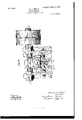
- Figure 1 is a sectional side elevation showing a head-motion embodying the features of my invention.
- Fig. 2 is an end elevation of the same.
- Fig. 3 is a plan view, parts being in section and parts removed for the sake of clearness.
- Figs. 4 and 5 are detail views of the toggle.
- the frame a is provided with side brackets b, at the upper portions of which are bearings 0.
- a cranked shaft d In these bearings turns a cranked shaft d, one end of which may carry fast and loose pulleys, which pulleys may be driven in either direction. Any suitable driving means may be employed.
- the eccentric portion cl for said shaft (Z, and which is located between the bearings c, has mounted thereon one end of a pitman e, which is carried round in a circle by means of the said eccentric portion. Other means may evidently be substituted for accomplishing the desired reciprocating motion of the pitman.
- the opposite end of the said pitman is preferably compelled to travel in the arc of a circle, which may be effectuated by means of two links f, which links extend from the pitman at some point forward of the vertical central line through the shaft (Z, in reference to the attaching-point of the table or object to be shaken.
- Said links f are tension links or connections.
- a pin g connects said links with the pitman, and the links are pivotally supported on the frame at f. Means other than those shown may be employed for guiding the free end of the toggle in the desired path, which need not necessarily be arcuate. This is evident without illustration and is intended to be comprehended by the invention.
- a link h is preferably pivoted to the frame a at it, and through its other end there passes a pin or short shaft connecting pull-rods 2'.
- a toggle 70 Located between and having bearing on the pins or shafts g and if is a toggle 70.
- This toggle preferably consists of a part such as shown in detail in Figs. 4 and 5 and comprises a shank portion k, a yoke portion 70 and a half-box 7x on each bifurcation of the yoke and another half-box It" at the other end of the toggle.
- the half-box 7c bears on the pin or shaft 9, carried by the pitman a, while the other half-boxes 70 are located one on each side of the link it for bearing on the pin or shaft if.
- the movement of the outer or yoke end of said toggle is controlled by the pin if and the. aforesaid link 72
- the toggle is preferably provided with means for lubrication,
- said link For the purpose of adjusting the link it preferably as to its length and for moving the point or pin 71, relatively to the other moving parts, said link It is for convenience composed of two sections 70 if, provided with right and left screw-threaded bores or sockets to receive the right and left screwthreaded ends of a short shaft 7L6, provided with a turning-head it and forming thereby a turnbuckle.
- the described or equivalent adjustment of the link causes a difference in the length or intensity of stroke of the table or other object which is suitably held to the point at if.
- the pull-rods may, if desired, be connected with the part to be actuated through the medium of a rocking lever m, which is pivoted at one end at m to the frame a, the pull-rods being pivoted thereto at i.
- the said rocking lever is connected with the part to be actuated by means of links or rods 07., the inner ends of which are pivotally supported on a cross-head 0, which is internally screwthreaded to receive a screw-spindle 9, whereby the said cross-head may be moved along guidewaysp of the lever m.
- the purpose of the intermediate connection afforded by the lever on and concomitant parts is for adjusting the stroke and intensity of movement.
- the action in the embodiment of the invention shown is as follows:
- the eccentric d imparts a reciprocating motion to the pitman and an oscillatory motion to the links 'f, which results in raising the pin 9 and through the toggle is urging the pin 7L2 and links 2' toward the left and moving the part to be actuated at a grad ually-decreasing velocity.
- On the return stroke the elocity gradually increases, so that by mean of the toggle and preferably by means of the vibratory motions of the links or connectin rods the peculiar quality of motion desire is obtained.
- toggle con mplates an elemental moving piece of machinery which sustains compression only.
- the head-motion described therefore contains a toggle which preferably projects, although not necessarily, from the pitman in a direction away from the part to be actuated, such as an ore-concentrating table, and both ends of which are in action, in this instance moving in arcs of circles.
- a head-motion comprising a pitman, means for restraining the free end of the pitman except as to reciprocation, a link pivoted at one end to a stationary object, an actuating-bar pivoted to the free end of said link, and a toggle directly connecting the free ends of said pitman and of said link.
- a head-motion comprising a pitman, a link pivoted at one end to astationary object and at the other end to said pitman, a second link pivoted atone end to a stationary object, an actuating-bar pivoted to the free end of the link, and a toggle directly connecting the free ends of said pitman and of said link.
- a head-motion comprising a pitman, means for restraining the free end of the pitman except as to reciprocation, a longitudinally-adjustable link pivoted at one end to a stationary object, an actuating-bar pivoted to the free end of said link, and a toggle directly connecting the free ends of said pitman and of said link.
- a head-motion comprising a pitman, means for restraining the free end of the pitman exceptas to reciprocation, a link pivoted at one end to a stationary object, an actuatingbar pivoted to the free end ofsaid link. a toggle directly connecting the free ends of said pitman and of said link, and means connected with the free end of said bar for varying the travel of a reciprocated object attached thereto.
- a head-motion comprising a pitman, means for restraining the free end of the pitman except as to reciprocation, a link pivoted at one end to astationary object, an actuatingbar pivoted to the free end of said link, a toggle directly connecting the free ends of said pitman and of said link, a rocking lever pivoted at one end to a stationary object and pivotally connected with said actuating-bar, a link-pivotally connected to said rocking lever, and means for varying the point of attachment of said link to said rocking lever.
- a head-motion comprising a pitman, means for restraining the free end'of the pitman except as to reciprocation.
- a link pivoted at one end to a stationary object, an actuatingbar pivoted to the free end of said link, a toggle directly connecting the free ends of said pitman and of said link, a rocking lever pivoted at one end to a stationary object and pivotally connected with said actuating-bar, a longitudinally movable crosshead in said rocking lever, and a link pivotally attached to said cross-head.
Landscapes
- Engineering & Computer Science (AREA)
- General Engineering & Computer Science (AREA)
- Mechanical Engineering (AREA)
- Transmission Devices (AREA)
Description
No. 802,016. PATENTED OCT. 17, 1905.
H. D. MoLEOD.
HEAD MOTION.
APPLICATION FILED JULY'8,1904.
3 SHEETS-MEET 1.
No. 802,016. PATENTED OCT. 17, 1905. H. D. MQLEOD. HEAD MOTION.
APPLIOATION FILED JULY 8,1904.
3 SHEETS-SHEET 2.
ANDREW a mum C0, PHOIO-UYNOGRAPNERS, WASNNGYOVL u c.
N0. 802,016. PATENTED OCT. 17, 1905.
D. McLEOD. HEAD MOTION.
APPLICATION FILED JULY 8,1904.
3 SHEETS-SHEET 3.
HOWARD D. MOLEOD, OF GREATFALLS, MONTANA.
'HEAD-IVIOTION.
Specification of Letters Patent.
Patented Oct. 17, 1905.
Application filed July 8, 1904. Serial No- 215,725.
To aZZ whom, it may concern:
Be it known that I, HOWARD D. MCLEOD, a citizen of the United States, residing at Greatfalls, county of Cascade, Montana, have invented certain new and useful Improvements in Head-Motions, of which the following is a specification.
This invention relates to head-motions for imparting a reciprocatory movementto oreconcentrating tables of the Rittinger, Gammett, VVilfley, and other types, and, in fact, to other devices requiring a shaking motion, as to shaking screens, grizzlies, and pickingtables.
One of the objects of the invention is to provide mechanism capable of imparting the desired progressive motion to the particles, especially on an ore-concentrating table, so that any material placed upon the table will be caused to advance along the table-surface in the proper manner, the mechanism being capable of such adjustment as to adapt it to different classes of ores and their attendant gangue.
A further object of the invention is to provide means for obtaining great differences of amplitude of reciprocation and great changes in speed, so that the table may be driven a large number of strokes per minute at small amplitude for very fine mesh material or a smaller number of strokes per minute at greater amplitude of reciprocation. This object is obtained by an exceedingly simple mechanism.
Another object of my invention is to provide a simple means for securing the adjustment of the length of the stroke entirely independent of any adjustment of the quality of the stroke, which latteris obtained in the head-motion alone.
Further objects of the invention will appear hereinafter.
My invention consists of certain features and combinations hereinafter described and claimed, reference being had to the accompanying drawings as showing a suitable form of my invention, and in which.
Figure 1 is a sectional side elevation showing a head-motion embodying the features of my invention. Fig. 2 is an end elevation of the same. Fig. 3 is a plan view, parts being in section and parts removed for the sake of clearness. Figs. 4 and 5 are detail views of the toggle.
Referring to the drawings, the frame a is provided with side brackets b, at the upper portions of which are bearings 0. In these bearings turns a cranked shaft d, one end of which may carry fast and loose pulleys, which pulleys may be driven in either direction. Any suitable driving means may be employed. The eccentric portion cl for said shaft (Z, and which is located between the bearings c, has mounted thereon one end of a pitman e, which is carried round in a circle by means of the said eccentric portion. Other means may evidently be substituted for accomplishing the desired reciprocating motion of the pitman. The opposite end of the said pitman is preferably compelled to travel in the arc of a circle, which may be effectuated by means of two links f, which links extend from the pitman at some point forward of the vertical central line through the shaft (Z, in reference to the attaching-point of the table or object to be shaken. Said links f are tension links or connections. A pin g connects said links with the pitman, and the links are pivotally supported on the frame at f. Means other than those shown may be employed for guiding the free end of the toggle in the desired path, which need not necessarily be arcuate. This is evident without illustration and is intended to be comprehended by the invention. A link h is preferably pivoted to the frame a at it, and through its other end there passes a pin or short shaft connecting pull-rods 2'.
Located between and having bearing on the pins or shafts g and if is a toggle 70. This toggle preferably consists of a part such as shown in detail in Figs. 4 and 5 and comprises a shank portion k, a yoke portion 70 and a half-box 7x on each bifurcation of the yoke and another half-box It" at the other end of the toggle. The half-box 7c bears on the pin or shaft 9, carried by the pitman a, while the other half-boxes 70 are located one on each side of the link it for bearing on the pin or shaft if. The movement of the outer or yoke end of said toggle is controlled by the pin if and the. aforesaid link 72 The toggle is preferably provided with means for lubrication,
(indicated at 1'.) For the purpose of adjusting the link it preferably as to its length and for moving the point or pin 71, relatively to the other moving parts, said link It is for convenience composed of two sections 70 if, provided with right and left screw-threaded bores or sockets to receive the right and left screwthreaded ends of a short shaft 7L6, provided with a turning-head it and forming thereby a turnbuckle. The described or equivalent adjustment of the link it causes a difference in the length or intensity of stroke of the table or other object which is suitably held to the point at if.
The pull-rods may, if desired, be connected with the part to be actuated through the medium of a rocking lever m, which is pivoted at one end at m to the frame a, the pull-rods being pivoted thereto at i. The said rocking lever is connected with the part to be actuated by means of links or rods 07., the inner ends of which are pivotally supported on a cross-head 0, which is internally screwthreaded to receive a screw-spindle 9, whereby the said cross-head may be moved along guidewaysp of the lever m. The purpose of the intermediate connection afforded by the lever on and concomitant parts is for adjusting the stroke and intensity of movement. The action in the embodiment of the invention shown is as follows: The eccentric d imparts a reciprocating motion to the pitman and an oscillatory motion to the links 'f, which results in raising the pin 9 and through the toggle is urging the pin 7L2 and links 2' toward the left and moving the part to be actuated at a grad ually-decreasing velocity. On the return stroke the elocity gradually increases, so that by mean of the toggle and preferably by means of the vibratory motions of the links or connectin rods the peculiar quality of motion desire is obtained.
It is to be understoo hat the word toggle used herein con mplates an elemental moving piece of machinery which sustains compression only. The head-motion described therefore contains a toggle which preferably projects, although not necessarily, from the pitman in a direction away from the part to be actuated, such as an ore-concentrating table, and both ends of which are in action, in this instance moving in arcs of circles.
Having thus described my invention and without limiting myself to details, asobviously some of the features may be used Without others or in combination with others, what I claim as new therein, and desire to secure by Letters Patent, is-
1. A head-motion comprising a pitman, means for restraining the free end of the pitman except as to reciprocation, a link pivoted at one end to a stationary object, an actuating-bar pivoted to the free end of said link, and a toggle directly connecting the free ends of said pitman and of said link.
2. A head-motion comprising a pitman, a link pivoted at one end to astationary object and at the other end to said pitman, a second link pivoted atone end to a stationary object, an actuating-bar pivoted to the free end of the link, and a toggle directly connecting the free ends of said pitman and of said link.
3. A head-motion comprising a pitman, means for restraining the free end of the pitman except as to reciprocation, a longitudinally-adjustable link pivoted at one end to a stationary object, an actuating-bar pivoted to the free end of said link, and a toggle directly connecting the free ends of said pitman and of said link.
4. A head-motion comprising a pitman, means for restraining the free end of the pitman exceptas to reciprocation, a link pivoted at one end to a stationary object, an actuatingbar pivoted to the free end ofsaid link. a toggle directly connecting the free ends of said pitman and of said link, and means connected with the free end of said bar for varying the travel of a reciprocated object attached thereto.
5. A head-motion comprising a pitman, means for restraining the free end of the pitman except as to reciprocation, a link pivoted at one end to astationary object, an actuatingbar pivoted to the free end of said link, a toggle directly connecting the free ends of said pitman and of said link, a rocking lever pivoted at one end to a stationary object and pivotally connected with said actuating-bar, a link-pivotally connected to said rocking lever, and means for varying the point of attachment of said link to said rocking lever.
.6. A head-motion comprising a pitman, means for restraining the free end'of the pitman except as to reciprocation. a link pivoted at one end to a stationary object, an actuatingbar pivoted to the free end of said link, a toggle directly connecting the free ends of said pitman and of said link, a rocking lever pivoted at one end to a stationary object and pivotally connected with said actuating-bar, a longitudinally movable crosshead in said rocking lever, and a link pivotally attached to said cross-head.
In testimony whereof I have signed this specification in the presence of two subscribing witnesses.
HOWARD D. McLEOD.
Witnesses:
W. A. VVEBsTER, CHARLES E. Rowe.
Priority Applications (1)
| Application Number | Priority Date | Filing Date | Title |
|---|---|---|---|
| US21572504A US802016A (en) | 1904-07-08 | 1904-07-08 | Head-motion. |
Applications Claiming Priority (1)
| Application Number | Priority Date | Filing Date | Title |
|---|---|---|---|
| US21572504A US802016A (en) | 1904-07-08 | 1904-07-08 | Head-motion. |
Publications (1)
| Publication Number | Publication Date |
|---|---|
| US802016A true US802016A (en) | 1905-10-17 |
Family
ID=2870502
Family Applications (1)
| Application Number | Title | Priority Date | Filing Date |
|---|---|---|---|
| US21572504A Expired - Lifetime US802016A (en) | 1904-07-08 | 1904-07-08 | Head-motion. |
Country Status (1)
| Country | Link |
|---|---|
| US (1) | US802016A (en) |
-
1904
- 1904-07-08 US US21572504A patent/US802016A/en not_active Expired - Lifetime
Similar Documents
| Publication | Publication Date | Title |
|---|---|---|
| US802016A (en) | Head-motion. | |
| US444016A (en) | Mechanical movement | |
| US156063A (en) | Improvement in flour and middlings separators | |
| US773210A (en) | Conveyer. | |
| US543768A (en) | Grain-scalper | |
| US1274196A (en) | Pattern-cutting machine. | |
| US1120304A (en) | Head mechanism for shaking-tables. | |
| US896547A (en) | Mechanical movement. | |
| US743379A (en) | Mechanical movement. | |
| US767481A (en) | Mechanical movement. | |
| US821003A (en) | Power-transmitting apparatus. | |
| US159414A (en) | Improvement in grain-separators | |
| US410474A (en) | Saw-mill | |
| US793354A (en) | Vibrator. | |
| US788025A (en) | Pulp-screening machine. | |
| US178125A (en) | Improvement in steam-engines | |
| US1034302A (en) | Flour-sifter. | |
| US254590A (en) | Flaxseed-cleaner | |
| US250523A (en) | Geoege w | |
| US670087A (en) | Shaking-screen. | |
| US825081A (en) | Ore-screening machine. | |
| US282752A (en) | Pottery-lawn | |
| US223487A (en) | Geoege dalton | |
| US926802A (en) | Power-hacksaw. | |
| US472275A (en) | salenius |