US8012417B2 - Solution discharging method and solution discharging device - Google Patents
Solution discharging method and solution discharging device Download PDFInfo
- Publication number
- US8012417B2 US8012417B2 US11/797,630 US79763007A US8012417B2 US 8012417 B2 US8012417 B2 US 8012417B2 US 79763007 A US79763007 A US 79763007A US 8012417 B2 US8012417 B2 US 8012417B2
- Authority
- US
- United States
- Prior art keywords
- pressure
- valve
- solution
- capillary
- air
- Prior art date
- Legal status (The legal status is an assumption and is not a legal conclusion. Google has not performed a legal analysis and makes no representation as to the accuracy of the status listed.)
- Expired - Fee Related, expires
Links
Images


Classifications
-
- C—CHEMISTRY; METALLURGY
- C12—BIOCHEMISTRY; BEER; SPIRITS; WINE; VINEGAR; MICROBIOLOGY; ENZYMOLOGY; MUTATION OR GENETIC ENGINEERING
- C12N—MICROORGANISMS OR ENZYMES; COMPOSITIONS THEREOF; PROPAGATING, PRESERVING, OR MAINTAINING MICROORGANISMS; MUTATION OR GENETIC ENGINEERING; CULTURE MEDIA
- C12N15/00—Mutation or genetic engineering; DNA or RNA concerning genetic engineering, vectors, e.g. plasmids, or their isolation, preparation or purification; Use of hosts therefor
- C12N15/09—Recombinant DNA-technology
- C12N15/87—Introduction of foreign genetic material using processes not otherwise provided for, e.g. co-transformation
- C12N15/89—Introduction of foreign genetic material using processes not otherwise provided for, e.g. co-transformation using microinjection
-
- C—CHEMISTRY; METALLURGY
- C12—BIOCHEMISTRY; BEER; SPIRITS; WINE; VINEGAR; MICROBIOLOGY; ENZYMOLOGY; MUTATION OR GENETIC ENGINEERING
- C12M—APPARATUS FOR ENZYMOLOGY OR MICROBIOLOGY; APPARATUS FOR CULTURING MICROORGANISMS FOR PRODUCING BIOMASS, FOR GROWING CELLS OR FOR OBTAINING FERMENTATION OR METABOLIC PRODUCTS, i.e. BIOREACTORS OR FERMENTERS
- C12M35/00—Means for application of stress for stimulating the growth of microorganisms or the generation of fermentation or metabolic products; Means for electroporation or cell fusion
-
- C—CHEMISTRY; METALLURGY
- C12—BIOCHEMISTRY; BEER; SPIRITS; WINE; VINEGAR; MICROBIOLOGY; ENZYMOLOGY; MUTATION OR GENETIC ENGINEERING
- C12M—APPARATUS FOR ENZYMOLOGY OR MICROBIOLOGY; APPARATUS FOR CULTURING MICROORGANISMS FOR PRODUCING BIOMASS, FOR GROWING CELLS OR FOR OBTAINING FERMENTATION OR METABOLIC PRODUCTS, i.e. BIOREACTORS OR FERMENTERS
- C12M41/00—Means for regulation, monitoring, measurement or control, e.g. flow regulation
- C12M41/12—Means for regulation, monitoring, measurement or control, e.g. flow regulation of temperature
-
- C—CHEMISTRY; METALLURGY
- C12—BIOCHEMISTRY; BEER; SPIRITS; WINE; VINEGAR; MICROBIOLOGY; ENZYMOLOGY; MUTATION OR GENETIC ENGINEERING
- C12M—APPARATUS FOR ENZYMOLOGY OR MICROBIOLOGY; APPARATUS FOR CULTURING MICROORGANISMS FOR PRODUCING BIOMASS, FOR GROWING CELLS OR FOR OBTAINING FERMENTATION OR METABOLIC PRODUCTS, i.e. BIOREACTORS OR FERMENTERS
- C12M41/00—Means for regulation, monitoring, measurement or control, e.g. flow regulation
- C12M41/40—Means for regulation, monitoring, measurement or control, e.g. flow regulation of pressure
-
- G—PHYSICS
- G01—MEASURING; TESTING
- G01N—INVESTIGATING OR ANALYSING MATERIALS BY DETERMINING THEIR CHEMICAL OR PHYSICAL PROPERTIES
- G01N35/00—Automatic analysis not limited to methods or materials provided for in any single one of groups G01N1/00 - G01N33/00; Handling materials therefor
- G01N35/10—Devices for transferring samples or any liquids to, in, or from, the analysis apparatus, e.g. suction devices, injection devices
- G01N35/1009—Characterised by arrangements for controlling the aspiration or dispense of liquids
- G01N35/1016—Control of the volume dispensed or introduced
-
- G—PHYSICS
- G01—MEASURING; TESTING
- G01N—INVESTIGATING OR ANALYSING MATERIALS BY DETERMINING THEIR CHEMICAL OR PHYSICAL PROPERTIES
- G01N35/00—Automatic analysis not limited to methods or materials provided for in any single one of groups G01N1/00 - G01N33/00; Handling materials therefor
- G01N35/10—Devices for transferring samples or any liquids to, in, or from, the analysis apparatus, e.g. suction devices, injection devices
- G01N35/1095—Devices for transferring samples or any liquids to, in, or from, the analysis apparatus, e.g. suction devices, injection devices for supplying the samples to flow-through analysers
-
- Y—GENERAL TAGGING OF NEW TECHNOLOGICAL DEVELOPMENTS; GENERAL TAGGING OF CROSS-SECTIONAL TECHNOLOGIES SPANNING OVER SEVERAL SECTIONS OF THE IPC; TECHNICAL SUBJECTS COVERED BY FORMER USPC CROSS-REFERENCE ART COLLECTIONS [XRACs] AND DIGESTS
- Y10—TECHNICAL SUBJECTS COVERED BY FORMER USPC
- Y10T—TECHNICAL SUBJECTS COVERED BY FORMER US CLASSIFICATION
- Y10T137/00—Fluid handling
- Y10T137/206—Flow affected by fluid contact, energy field or coanda effect [e.g., pure fluid device or system]
- Y10T137/218—Means to regulate or vary operation of device
- Y10T137/2202—By movable element
- Y10T137/2218—Means [e.g., valve] in control input
Definitions
- the present invention generally relates to injecting material in the cells by using air pressure.
- FIG. 6 is an example of a conventional device.
- reference numeral 1 denotes a positive pressure pump
- reference numeral 2 denotes a negative pressure pump
- Reference numeral 3 denotes a regulator that is connected to the positive pressure pump 1 and the negative pressure pump 2 for keeping constant the internal pressures thereof.
- Reference numeral 4 denotes a capillary that discharges a solution into a cell due to the pressure from the regulator 3 .
- the capillary 4 is similar to an injection syringe, and has a fine needle at its tip.
- the internal diameter of the tip is 0.5 ⁇ m and the external diameter is 1 ⁇ m.
- Reference numeral 6 denotes a tube that transmits the pressure from the regulator 3 to the capillary 4
- reference numeral 5 denotes a pressure sensor which is located in the middle of the tube 6 .
- the pressure detected by the pressure sensor 5 is output to the regulator 3 , and the regulator 3 adjusts the internal pressure so that the pressure detected by the pressure sensor 5 is maintained constant. Otherwise, it is possible to arrange the pressure sensor inside the regulator 3 and adjust the internal pressure so as to maintain constant output from the pressure sensor. Electric voltage is input to the regulator 3 as a control signal, and the regulator 3 generates a pressure that is proportional to the input electric voltage.
- the needle attached to the tip of the capillary 4 is filled with the solution.
- Pressure applied by the regulator 3 thrusts a cylinder of the capillary 4 whereby the solution is discharged (injected) into the cell.
- the cell is observed for a change that occurs after injection of the solution.
- FIG. 7 depicts a pressure response curve of the conventional device.
- a horizontal axis indicates time and a vertical axis indicates pressure.
- the pressure is maintained to reverse flow preventing pressure.
- T 1 time
- T 2 time
- the conventional device can be used in a gene delivery device.
- cells that flow through a micro fluid channel are observed by using a cell observing device, cells are trapped one by one with a cell trapping device, and genetic material and medicinal solutions are discharged into the cells by using a gene delivering micro needle (for example, see Japanese Patent Application Laid-Open No. 2004-166653).
- a microinjection apparatus has, at its tip, a micro instrument that is connected to a micro syringe, which is filled with the solution. When a male screw is rotated to move a plunger, into the micro syringe, the solution is discharged from the micro instrument (for example, see Japanese Patent Application Laid-Open No. H03-119989).
- a microinjecting method of the microinjection apparatus involves filling predetermined volume of a solution in an extra fine capillary, with a tip that is of ⁇ m order, injecting the solution into the cell by pressurizing the capillary, and observing the response. In this process, it is necessary to control sequentially switching of the pressure between a pressure necessary for discharging the solution in the cell and a pressure necessary for preventing reverse flow of the solution into the capillary.
- the conventional microinjection device which has the structure shown in FIG. 6 , does not take into account the pressure transient response. Therefore, when trace quantity of solution of pl (picolitre) order is to be discharged through injections such as injections into animal cells, if the delivery time is lowered to less than 1 second for speeding a discharge cycle, the set pressure and the set time deviate from the actual response, and adjustment of discharging volume of the solution is difficult.
- a solution discharging method for discharging a solution, from a hollow capillary with a narrow tip that is filled with the solution, into a cell due to an action of air pressure includes connecting a regulating chamber to the capillary by a valve; and regulating air in the regulating chamber at a predetermined pressure before opening and closing the valve so that regulated pressure has a rectangular waveform thereby controlling quantity of the solution that is to be injected from the capillary into the cell to be constant.
- a microinjection device includes a pressure pump; a regulator that is connected to the pressure pump and that maintains constant pressure; a regulating chamber that is connected to the regulator and an internal pressure of which is maintained to a predetermined pressure; a valve that is connected to the regulating chamber; and a capillary that is connected to the valve and that is used to inject solution in a cell.
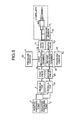
- FIG. 1 is a schematic of a first embodiment according to the present invention
- FIG. 2 is a graph for explaining a pressure response according to the present invention.
- FIG. 3 is a schematic of a second embodiment according to the present invention.
- FIG. 4 is a schematic of a third embodiment according to the present invention.
- FIG. 5 is a schematic of a fourth embodiment according to the present invention.
- FIG. 6 is a schematic of an example of the structure of a conventional device.
- FIG. 7 is a graph for explaining a pressure response of the conventional device.
- FIG. 1 is a schematic of a first embodiment of the present invention. Components that are same as those shown in FIG. 6 are indicated with the same reference numerals.
- reference numeral 1 denotes a positive pressure pump
- reference numeral 2 denotes a negative pressure pump
- Reference numeral 3 denotes a regulator that regulates the pressure
- reference numeral 10 denotes a regulating chamber that contains air whose pressure is regulated by the regulator 3
- Reference numeral 5 denotes a second pressure sensor that detects pressure in the regulating chamber 10 . The output of the second pressure sensor 5 is input in the regulator 3 .
- Reference numeral 4 denotes a capillary that injects solution into an animal cell and the like
- reference numeral 11 denotes a valve arranged in between the regulating chamber 10 and the capillary 4 .
- the valve 11 in which the material used is for example solenoid, is opened and closed to transmit air from the regulating chamber 10 to the capillary 4
- Reference numeral 12 denotes a pressure sensor 1 that detects pressure of air in the capillary 4 .
- the pressure of air inside the capillary 4 is P 1
- the volume is V 1 . Operation of the apparatus, which has such configuration, is explained below.
- pressure of the regulating chamber 10 is set by the regulator 3 to a certain degree higher than the injection pressure.
- the operator while watching under a microscope, confirms that a needle of the capillary 4 reaches the cell, the operator opens the valve 11 to bring the pressure to injection pressure level.
- the valve 11 is immediately closed. While the capillary 4 is discharging (injecting) the solution into the cell, the regulator 3 adjusts pressure in the regulating chamber 10 and sets it to lower level of than the reverse flow preventing pressure.
- the valve 11 when the valve 11 is opened, pressure in the regulating chamber 10 and the capillary 4 becomes equal to the reverse flow preventing pressure, which prevents the solution from reverting into the capillary 4 .
- the regulating chamber 10 is set to lower than the reverse flow preventing pressure in advance, which makes it possible to bring the level of the pressure entirely to the reverse flow preventing pressure, when the valve 11 is opened.
- the pressure P after the opening of the valve is set in advance
- the pressure P 1 in the capillary before the opening of the valve is known in advance from an output from the pressure sensor 12 ; therefore, it is possible to calculate the pressure P 2 of the regulator before the opening of the valve through Equation (3).
- the pressure P 2 of the regulator before the opening of the valve is set to the value derived through Equation (3)
- the pressure at the time of opening of the valve 11 is regulated to the pressure P. That is, it is possible to maintain the pressure in the regulating chamber and the capillary.
- FIG. 7 Pressure response in an ordinary microinjection device is as shown in FIG. 7 .
- the pressure is transmitted at a sonic speed.
- the pressure response in such a case is as shown in a graph in FIG. 2 .
- FIG. 2 is a graph for explaining the pressure response according to the present invention.
- the horizontal axis is time and the vertical axis is the pressure.
- time interval required for responding to regulation of the pressure to the injection pressure level is still shorter than the response as shown in FIG. 7 .
- FIG. 7 in the characteristic of the conventional device, the time required to attain target value is longer, whereas the transient response of the device in the present invention is only represented by vibrations near the target value. If the integration value of the vibrations is considered zero, it can be thought that the total quantity of injecting solution is proportional to a product of the target pressure and the time required for application of the pressure.
- a valve is arranged in between a regulating chamber and a capillary, and opened and closed to control the discharging quantity of solution from the capillary into a cell. That is, when the solution is injected into a cell, the quantity of solution can be easily controlled, and stable microinjection can be performed at high speed with less effect of transient response.
- speedy rise of pressure in the capillary produces a rectangular waveform that depicts high degree of accuracy in time required for application of the pressure, high speed injection cycle, and improved accuracy of the quantity of the injecting solution.
- the quantity of the injecting solution is proportional to pressure and time for which the pressure is applied; therefore, even if there is transient response, a method of controlling the quantity of the injecting solution according to the pressure time integration also has the same effect on the accuracy of the quantity of the injecting solution. That is, according to the present invention, because the integration value of the pressure applied to the capillary and the time for which the pressure is applied is controlled to a predetermined value, it is possible to always control the quantity of the injecting solution to a constant quantity.
- FIG. 3 is a schematic of a second embodiment according to the present invention. Components that are same as those in FIG. 1 are indicated with the same reference numerals.
- the embodiment includes a second valve 15 in between the regulator 3 and the regulating chamber 10 . Other aspects of the structure are same as shown in FIG. 1 .
- FIG. 4 is a schematic of a third embodiment according to the present invention. Components that are same as those in FIG. 3 are indicated with the same reference numerals.
- reference numeral 25 denotes a second valve, which is connected to the regulator 3 ;
- reference numeral 20 denotes a second regulating chamber connected to the second valve;
- reference numeral 21 denotes a fourth valve that is connected to the second regulating chamber.
- Reference numeral 22 denotes a pressure sensor that detects a pressure Pi in the first regulating chamber, and reference numeral 23 denotes a pressure sensor that detects a pressure Pc in the second regulating chamber.
- Reference numeral 12 denotes a pressure sensor that detects the pressure in the capillary.
- Reference numeral 15 denotes the first valve
- reference numeral 10 denotes the first regulating chamber connected to the first valve
- reference numeral 11 denotes a third valve connected to the first regulating chamber.
- the first valve and the second valve are commonly connected to the regulator 3
- the third valve and the fourth valve are commonly connected to the capillary 4 .
- a double system of the regulator units formed of valves regulators, and valves.
- the third valve is closed, and the capillary 4 is injecting the solution in the cell, there is no need to regulate the regulating chamber 10 . That is, when one system is operating the capillary 4 , another system regulates the regulating chamber, and when injection operation of the capillary 4 is completed, opening of the fourth valve leads to a faster regulation after the opening of the valve.
- time required to switch valves from one state to another is shortened.
- FIG. 5 is a schematic of a fourth embodiment according to the present invention. Components that are same as those in FIG. 4 are indicated with the same reference numerals.
- the embodiment includes a second regulator 30 corresponding to the second regulation system shown in FIG. 4 .
- the second regulator 30 is connected to the positive pump 1 and the negative pump 2 , and is independent of a first regulator 3 .
- the second regulator 30 is connected to the second valve. Remaining structure is the same as that shown in FIG. 4 .
- Such a structure allows the regulator 3 and a regulator 30 to adjust the air pressure in the regulator chamber independently, which allows the two systems to operate independently, and this structure operates faster than the one shown in FIG. 4 .
- high accuracy of time for which pressure is applied can be achieved due to fast rise in pressure response that creates rectangular waveform, and it is possible to have faster injection cycle and improve accuracy in quantity of discharging solution.
Landscapes
- Health & Medical Sciences (AREA)
- Life Sciences & Earth Sciences (AREA)
- Engineering & Computer Science (AREA)
- Genetics & Genomics (AREA)
- Chemical & Material Sciences (AREA)
- Bioinformatics & Cheminformatics (AREA)
- Organic Chemistry (AREA)
- Zoology (AREA)
- Wood Science & Technology (AREA)
- Biotechnology (AREA)
- Biomedical Technology (AREA)
- General Engineering & Computer Science (AREA)
- Microbiology (AREA)
- Biochemistry (AREA)
- General Health & Medical Sciences (AREA)
- Sustainable Development (AREA)
- Physics & Mathematics (AREA)
- Analytical Chemistry (AREA)
- Biophysics (AREA)
- Molecular Biology (AREA)
- Plant Pathology (AREA)
- Cell Biology (AREA)
- Thermal Sciences (AREA)
- Apparatus Associated With Microorganisms And Enzymes (AREA)
- Measuring Or Testing Involving Enzymes Or Micro-Organisms (AREA)
- Automatic Analysis And Handling Materials Therefor (AREA)
- Sampling And Sample Adjustment (AREA)
Abstract
Description
P=(ηP 1 +P 2)/(η+1)) (1)
η=V 1 /V 2=(P−P 2)/(P 1 −P) (2)
With the help of
P 2=(η+1)P−ηP 1 (3)
η can be calculated from
Claims (4)
Applications Claiming Priority (2)
| Application Number | Priority Date | Filing Date | Title |
|---|---|---|---|
| JP2006133512A JP5011812B2 (en) | 2006-05-12 | 2006-05-12 | Method for discharging liquid into cell and microinjection apparatus |
| JP2006-133512 | 2006-05-12 |
Publications (2)
| Publication Number | Publication Date |
|---|---|
| US20070264162A1 US20070264162A1 (en) | 2007-11-15 |
| US8012417B2 true US8012417B2 (en) | 2011-09-06 |
Family
ID=38235404
Family Applications (1)
| Application Number | Title | Priority Date | Filing Date |
|---|---|---|---|
| US11/797,630 Expired - Fee Related US8012417B2 (en) | 2006-05-12 | 2007-05-04 | Solution discharging method and solution discharging device |
Country Status (5)
| Country | Link |
|---|---|
| US (1) | US8012417B2 (en) |
| EP (1) | EP1854874B1 (en) |
| JP (1) | JP5011812B2 (en) |
| KR (1) | KR100870167B1 (en) |
| DE (1) | DE602007007011D1 (en) |
Families Citing this family (4)
| Publication number | Priority date | Publication date | Assignee | Title |
|---|---|---|---|---|
| JP2010035457A (en) * | 2008-08-01 | 2010-02-18 | Fujitsu Ltd | Injection device and method of injection by using the same |
| JP5272633B2 (en) * | 2008-10-06 | 2013-08-28 | 富士通株式会社 | Injection device |
| JP5141543B2 (en) * | 2008-12-25 | 2013-02-13 | 富士通株式会社 | Microinjection apparatus and backflow prevention pressure measuring method |
| CN115305182A (en) * | 2022-07-29 | 2022-11-08 | 北京脑科学与类脑研究中心 | Micro-drug delivery device and control system |
Citations (9)
| Publication number | Priority date | Publication date | Assignee | Title |
|---|---|---|---|---|
| GB2114740A (en) | 1982-02-05 | 1983-08-24 | Europ Lab Molekularbiolog | Method and apparatus for injecting miniscule quantities of samples into cells |
| JPH04304881A (en) | 1991-03-29 | 1992-10-28 | Shimadzu Corp | Equipment for injection |
| WO1993007256A1 (en) | 1991-10-07 | 1993-04-15 | Ciba-Geigy Ag | Particle gun for introducing dna into intact cells |
| US5225750A (en) | 1989-10-02 | 1993-07-06 | Prima Meat Packers, Ltd. | Microinjection apparatus, and method of controlling microinjection |
| DE4401076A1 (en) | 1994-01-15 | 1995-07-20 | Eppendorf Geraetebau Netheler | Injection appts. for biological cells |
| US5456880A (en) * | 1992-11-20 | 1995-10-10 | Shimadzu Corporation | Micropipet apparatus and micromanipulator |
| US20030070710A1 (en) * | 2001-10-12 | 2003-04-17 | Smc Kabushiki Kaisha | Fluid pressure regulator |
| US20030220585A1 (en) * | 2002-05-21 | 2003-11-27 | Hissong James B. | Apparatus and method for displacing the partition between the middle ear and the inner ear using a manually powered device |
| JP2004166653A (en) | 2002-11-22 | 2004-06-17 | Fujitsu Ltd | Transgenic cell manufacturing equipment |
Family Cites Families (6)
| Publication number | Priority date | Publication date | Assignee | Title |
|---|---|---|---|---|
| JPS62224361A (en) * | 1986-03-26 | 1987-10-02 | アイシン精機株式会社 | Auxiliary circulation machinery driving apparatus |
| JP2513359B2 (en) * | 1990-11-30 | 1996-07-03 | 株式会社島津製作所 | Micro pipette device |
| JP2003186549A (en) * | 2001-10-12 | 2003-07-04 | Smc Corp | Fluid pressure regulator |
| BRPI0506837A (en) * | 2004-01-12 | 2007-06-12 | Iscience Surgical Corp | viscous material injector, and devices and kit for providing micro-quantities of viscous materials |
| JP4456429B2 (en) * | 2004-07-27 | 2010-04-28 | 富士通株式会社 | Injection device |
| KR100597814B1 (en) * | 2005-10-31 | 2006-07-10 | (주)엠큐어 | Pneumatic injection gun |
-
2006
- 2006-05-12 JP JP2006133512A patent/JP5011812B2/en not_active Expired - Fee Related
-
2007
- 2007-04-02 EP EP20070105503 patent/EP1854874B1/en not_active Ceased
- 2007-04-02 DE DE200760007011 patent/DE602007007011D1/en active Active
- 2007-04-25 KR KR1020070040324A patent/KR100870167B1/en active IP Right Grant
- 2007-05-04 US US11/797,630 patent/US8012417B2/en not_active Expired - Fee Related
Patent Citations (10)
| Publication number | Priority date | Publication date | Assignee | Title |
|---|---|---|---|---|
| GB2114740A (en) | 1982-02-05 | 1983-08-24 | Europ Lab Molekularbiolog | Method and apparatus for injecting miniscule quantities of samples into cells |
| US4532205A (en) * | 1982-02-05 | 1985-07-30 | Europaisches Laboratorium Fur Molekularbiologie (Embl) | Process for the injection of very small amounts of samples into cells |
| US5225750A (en) | 1989-10-02 | 1993-07-06 | Prima Meat Packers, Ltd. | Microinjection apparatus, and method of controlling microinjection |
| JPH04304881A (en) | 1991-03-29 | 1992-10-28 | Shimadzu Corp | Equipment for injection |
| WO1993007256A1 (en) | 1991-10-07 | 1993-04-15 | Ciba-Geigy Ag | Particle gun for introducing dna into intact cells |
| US5456880A (en) * | 1992-11-20 | 1995-10-10 | Shimadzu Corporation | Micropipet apparatus and micromanipulator |
| DE4401076A1 (en) | 1994-01-15 | 1995-07-20 | Eppendorf Geraetebau Netheler | Injection appts. for biological cells |
| US20030070710A1 (en) * | 2001-10-12 | 2003-04-17 | Smc Kabushiki Kaisha | Fluid pressure regulator |
| US20030220585A1 (en) * | 2002-05-21 | 2003-11-27 | Hissong James B. | Apparatus and method for displacing the partition between the middle ear and the inner ear using a manually powered device |
| JP2004166653A (en) | 2002-11-22 | 2004-06-17 | Fujitsu Ltd | Transgenic cell manufacturing equipment |
Non-Patent Citations (1)
| Title |
|---|
| European Search Report issued in corresponding European Patent Application No. 07105503.2 dated Jul. 26, 2007 (7 pages). |
Also Published As
| Publication number | Publication date |
|---|---|
| EP1854874B1 (en) | 2010-06-09 |
| EP1854874A1 (en) | 2007-11-14 |
| JP5011812B2 (en) | 2012-08-29 |
| KR20070109832A (en) | 2007-11-15 |
| KR100870167B1 (en) | 2008-11-25 |
| DE602007007011D1 (en) | 2010-07-22 |
| US20070264162A1 (en) | 2007-11-15 |
| JP2007300868A (en) | 2007-11-22 |
Similar Documents
| Publication | Publication Date | Title |
|---|---|---|
| US8012417B2 (en) | Solution discharging method and solution discharging device | |
| DE102012209314B4 (en) | Device and method for dispensing or receiving a liquid volume | |
| US8910671B2 (en) | Apparatus for supplying electrolyte | |
| US8631785B2 (en) | Method for detecting deviations of injection quantities and for correcting the injection quantity, and injection system | |
| US10253712B2 (en) | Method for operating a piezo servo injector | |
| CN104696706A (en) | Micro fluid flow adjusting device based on air pressure drive | |
| CN104105861B (en) | For carrying out pressure controlled method in the high-pressure area of internal combustion engine | |
| WO2000024526A1 (en) | Liquid constant rate discharge method and device | |
| EP1562093A2 (en) | Dosing device | |
| US20110106407A1 (en) | Method and system for controlling fuel pressure | |
| CN109212246A (en) | Liquid feed device, sample analyser build pressure device and feed liquid method | |
| RU2015106128A (en) | METHOD, ENGINE SYSTEM AND METHOD FOR ENGINE (OPTIONS) | |
| CN111185347A (en) | Quantitative discharge device | |
| CN102590399B (en) | Sample injection device, sample injection method, and liquid chromatography device | |
| CN102818054A (en) | Power-assisted needle type back pressure control method and back pressure valve thereof | |
| JPH0564832A (en) | Measuring method and its device for injected resin | |
| JP4992369B2 (en) | Discharge amount control method, discharge pressure control method, injection device, method for manufacturing microscopic object, discharge amount control device, and discharge amount control program | |
| DE102015224622A1 (en) | FREISTRAHLDOSIERSYSTEM | |
| JP2006197880A (en) | Apparatus for catching cell and method for catching cell | |
| JP4130840B2 (en) | Method and apparatus for determining the charging edge of a piezoelectric actuator | |
| JP2010035457A (en) | Injection device and method of injection by using the same | |
| GB2433904A (en) | Pressure controlled nozzle arrangement | |
| DE102006021299A1 (en) | Internal-combustion engine`s e.g. diesel engine, injector controlling method, involves applying output voltage to piezo-actuator, and changing opening voltage to offset voltage and applying for distributing injection of injecting voltage | |
| JP2021530281A (en) | Methods and systems for delivering substances to body parts | |
| CN104608968B (en) | Big transfusion gravity bottle placer head tank liquid level controlling method and system |
Legal Events
| Date | Code | Title | Description |
|---|---|---|---|
| AS | Assignment |
Owner name: FUJITSU LIMITED, JAPAN Free format text: ASSIGNMENT OF ASSIGNORS INTEREST;ASSIGNORS:TANINAKA, KIYOSHI;SASAKI, JUN;YABUKI, AKIHIKO;REEL/FRAME:019335/0558;SIGNING DATES FROM 20070312 TO 20070314 Owner name: FUJITSU LIMITED, JAPAN Free format text: ASSIGNMENT OF ASSIGNORS INTEREST;ASSIGNORS:TANINAKA, KIYOSHI;SASAKI, JUN;YABUKI, AKIHIKO;SIGNING DATES FROM 20070312 TO 20070314;REEL/FRAME:019335/0558 |
|
| ZAAA | Notice of allowance and fees due |
Free format text: ORIGINAL CODE: NOA |
|
| ZAAB | Notice of allowance mailed |
Free format text: ORIGINAL CODE: MN/=. |
|
| STCF | Information on status: patent grant |
Free format text: PATENTED CASE |
|
| FEPP | Fee payment procedure |
Free format text: PAYOR NUMBER ASSIGNED (ORIGINAL EVENT CODE: ASPN); ENTITY STATUS OF PATENT OWNER: LARGE ENTITY |
|
| FPAY | Fee payment |
Year of fee payment: 4 |
|
| MAFP | Maintenance fee payment |
Free format text: PAYMENT OF MAINTENANCE FEE, 8TH YEAR, LARGE ENTITY (ORIGINAL EVENT CODE: M1552); ENTITY STATUS OF PATENT OWNER: LARGE ENTITY Year of fee payment: 8 |
|
| FEPP | Fee payment procedure |
Free format text: MAINTENANCE FEE REMINDER MAILED (ORIGINAL EVENT CODE: REM.); ENTITY STATUS OF PATENT OWNER: LARGE ENTITY |
|
| LAPS | Lapse for failure to pay maintenance fees |
Free format text: PATENT EXPIRED FOR FAILURE TO PAY MAINTENANCE FEES (ORIGINAL EVENT CODE: EXP.); ENTITY STATUS OF PATENT OWNER: LARGE ENTITY |
|
| STCH | Information on status: patent discontinuation |
Free format text: PATENT EXPIRED DUE TO NONPAYMENT OF MAINTENANCE FEES UNDER 37 CFR 1.362 |
|
| FP | Lapsed due to failure to pay maintenance fee |
Effective date: 20230906 |