US8011214B2 - Valet key storage device - Google Patents
Valet key storage device Download PDFInfo
- Publication number
- US8011214B2 US8011214B2 US12/203,021 US20302108A US8011214B2 US 8011214 B2 US8011214 B2 US 8011214B2 US 20302108 A US20302108 A US 20302108A US 8011214 B2 US8011214 B2 US 8011214B2
- Authority
- US
- United States
- Prior art keywords
- valet
- valet key
- key
- vehicle
- key storage
- Prior art date
- Legal status (The legal status is an assumption and is not a legal conclusion. Google has not performed a legal analysis and makes no representation as to the accuracy of the status listed.)
- Expired - Fee Related, expires
Links
- 230000003100 immobilizing effect Effects 0.000 claims description 15
- 230000037431 insertion Effects 0.000 claims 2
- 238000003780 insertion Methods 0.000 claims 2
- 230000006870 function Effects 0.000 description 18
- 238000004891 communication Methods 0.000 description 4
- 238000000151 deposition Methods 0.000 description 3
- 238000010586 diagram Methods 0.000 description 2
- 230000000694 effects Effects 0.000 description 2
- 239000000463 material Substances 0.000 description 2
- 239000007769 metal material Substances 0.000 description 2
- 238000000034 method Methods 0.000 description 2
- 238000003825 pressing Methods 0.000 description 2
- 239000011347 resin Substances 0.000 description 2
- 229920005989 resin Polymers 0.000 description 2
- 230000003213 activating effect Effects 0.000 description 1
- 238000013461 design Methods 0.000 description 1
- 238000002955 isolation Methods 0.000 description 1
- 230000000149 penetrating effect Effects 0.000 description 1
- 238000012545 processing Methods 0.000 description 1
- 238000000926 separation method Methods 0.000 description 1
- 238000012800 visualization Methods 0.000 description 1
Images


Classifications
-
- E—FIXED CONSTRUCTIONS
- E05—LOCKS; KEYS; WINDOW OR DOOR FITTINGS; SAFES
- E05B—LOCKS; ACCESSORIES THEREFOR; HANDCUFFS
- E05B19/00—Keys; Accessories therefor
- E05B19/0005—Key safes
-
- B—PERFORMING OPERATIONS; TRANSPORTING
- B60—VEHICLES IN GENERAL
- B60R—VEHICLES, VEHICLE FITTINGS, OR VEHICLE PARTS, NOT OTHERWISE PROVIDED FOR
- B60R25/00—Fittings or systems for preventing or indicating unauthorised use or theft of vehicles
- B60R25/20—Means to switch the anti-theft system on or off
- B60R25/24—Means to switch the anti-theft system on or off using electronic identifiers containing a code not memorised by the user
- B60R25/241—Means to switch the anti-theft system on or off using electronic identifiers containing a code not memorised by the user whereby access privileges are related to the identifiers
-
- B—PERFORMING OPERATIONS; TRANSPORTING
- B60—VEHICLES IN GENERAL
- B60R—VEHICLES, VEHICLE FITTINGS, OR VEHICLE PARTS, NOT OTHERWISE PROVIDED FOR
- B60R25/00—Fittings or systems for preventing or indicating unauthorised use or theft of vehicles
- B60R25/20—Means to switch the anti-theft system on or off
- B60R25/24—Means to switch the anti-theft system on or off using electronic identifiers containing a code not memorised by the user
- B60R25/248—Electronic key extraction prevention
-
- B—PERFORMING OPERATIONS; TRANSPORTING
- B60—VEHICLES IN GENERAL
- B60R—VEHICLES, VEHICLE FITTINGS, OR VEHICLE PARTS, NOT OTHERWISE PROVIDED FOR
- B60R7/00—Stowing or holding appliances inside vehicle primarily intended for personal property smaller than suit-cases, e.g. travelling articles, or maps
- B60R7/04—Stowing or holding appliances inside vehicle primarily intended for personal property smaller than suit-cases, e.g. travelling articles, or maps in driver or passenger space, e.g. using racks
-
- E—FIXED CONSTRUCTIONS
- E05—LOCKS; KEYS; WINDOW OR DOOR FITTINGS; SAFES
- E05B—LOCKS; ACCESSORIES THEREFOR; HANDCUFFS
- E05B47/00—Operating or controlling locks or other fastening devices by electric or magnetic means
- E05B47/02—Movement of the bolt by electromagnetic means; Adaptation of locks, latches, or parts thereof, for movement of the bolt by electromagnetic means
- E05B47/026—Movement of the bolt by electromagnetic means; Adaptation of locks, latches, or parts thereof, for movement of the bolt by electromagnetic means the bolt moving rectilinearly
-
- E—FIXED CONSTRUCTIONS
- E05—LOCKS; KEYS; WINDOW OR DOOR FITTINGS; SAFES
- E05B—LOCKS; ACCESSORIES THEREFOR; HANDCUFFS
- E05B47/00—Operating or controlling locks or other fastening devices by electric or magnetic means
- E05B47/0001—Operating or controlling locks or other fastening devices by electric or magnetic means with electric actuators; Constructional features thereof
- E05B47/0002—Operating or controlling locks or other fastening devices by electric or magnetic means with electric actuators; Constructional features thereof with electromagnets
- E05B47/0003—Operating or controlling locks or other fastening devices by electric or magnetic means with electric actuators; Constructional features thereof with electromagnets having a movable core
- E05B47/0004—Operating or controlling locks or other fastening devices by electric or magnetic means with electric actuators; Constructional features thereof with electromagnets having a movable core said core being linearly movable
-
- E—FIXED CONSTRUCTIONS
- E05—LOCKS; KEYS; WINDOW OR DOOR FITTINGS; SAFES
- E05B—LOCKS; ACCESSORIES THEREFOR; HANDCUFFS
- E05B81/00—Power-actuated vehicle locks
- E05B81/02—Power-actuated vehicle locks characterised by the type of actuators used
- E05B81/04—Electrical
- E05B81/08—Electrical using electromagnets or solenoids
-
- G—PHYSICS
- G07—CHECKING-DEVICES
- G07C—TIME OR ATTENDANCE REGISTERS; REGISTERING OR INDICATING THE WORKING OF MACHINES; GENERATING RANDOM NUMBERS; VOTING OR LOTTERY APPARATUS; ARRANGEMENTS, SYSTEMS OR APPARATUS FOR CHECKING NOT PROVIDED FOR ELSEWHERE
- G07C9/00—Individual registration on entry or exit
- G07C9/00174—Electronically operated locks; Circuits therefor; Nonmechanical keys therefor, e.g. passive or active electrical keys or other data carriers without mechanical keys
- G07C2009/00968—Electronically operated locks; Circuits therefor; Nonmechanical keys therefor, e.g. passive or active electrical keys or other data carriers without mechanical keys shape of the data carrier
-
- G—PHYSICS
- G07—CHECKING-DEVICES
- G07C—TIME OR ATTENDANCE REGISTERS; REGISTERING OR INDICATING THE WORKING OF MACHINES; GENERATING RANDOM NUMBERS; VOTING OR LOTTERY APPARATUS; ARRANGEMENTS, SYSTEMS OR APPARATUS FOR CHECKING NOT PROVIDED FOR ELSEWHERE
- G07C2209/00—Indexing scheme relating to groups G07C9/00 - G07C9/38
- G07C2209/04—Access control involving a hierarchy in access rights
-
- Y—GENERAL TAGGING OF NEW TECHNOLOGICAL DEVELOPMENTS; GENERAL TAGGING OF CROSS-SECTIONAL TECHNOLOGIES SPANNING OVER SEVERAL SECTIONS OF THE IPC; TECHNICAL SUBJECTS COVERED BY FORMER USPC CROSS-REFERENCE ART COLLECTIONS [XRACs] AND DIGESTS
- Y10—TECHNICAL SUBJECTS COVERED BY FORMER USPC
- Y10T—TECHNICAL SUBJECTS COVERED BY FORMER US CLASSIFICATION
- Y10T70/00—Locks
- Y10T70/50—Special application
- Y10T70/5889—For automotive vehicles
- Y10T70/5956—Steering mechanism with switch
-
- Y—GENERAL TAGGING OF NEW TECHNOLOGICAL DEVELOPMENTS; GENERAL TAGGING OF CROSS-SECTIONAL TECHNOLOGIES SPANNING OVER SEVERAL SECTIONS OF THE IPC; TECHNICAL SUBJECTS COVERED BY FORMER USPC CROSS-REFERENCE ART COLLECTIONS [XRACs] AND DIGESTS
- Y10—TECHNICAL SUBJECTS COVERED BY FORMER USPC
- Y10T—TECHNICAL SUBJECTS COVERED BY FORMER US CLASSIFICATION
- Y10T70/00—Locks
- Y10T70/70—Operating mechanism
- Y10T70/7441—Key
- Y10T70/7757—Push or pull key operation
-
- Y—GENERAL TAGGING OF NEW TECHNOLOGICAL DEVELOPMENTS; GENERAL TAGGING OF CROSS-SECTIONAL TECHNOLOGIES SPANNING OVER SEVERAL SECTIONS OF THE IPC; TECHNICAL SUBJECTS COVERED BY FORMER USPC CROSS-REFERENCE ART COLLECTIONS [XRACs] AND DIGESTS
- Y10—TECHNICAL SUBJECTS COVERED BY FORMER USPC
- Y10T—TECHNICAL SUBJECTS COVERED BY FORMER US CLASSIFICATION
- Y10T70/00—Locks
- Y10T70/70—Operating mechanism
- Y10T70/7441—Key
- Y10T70/7763—Key ejecting
-
- Y—GENERAL TAGGING OF NEW TECHNOLOGICAL DEVELOPMENTS; GENERAL TAGGING OF CROSS-SECTIONAL TECHNOLOGIES SPANNING OVER SEVERAL SECTIONS OF THE IPC; TECHNICAL SUBJECTS COVERED BY FORMER USPC CROSS-REFERENCE ART COLLECTIONS [XRACs] AND DIGESTS
- Y10—TECHNICAL SUBJECTS COVERED BY FORMER USPC
- Y10T—TECHNICAL SUBJECTS COVERED BY FORMER US CLASSIFICATION
- Y10T70/00—Locks
- Y10T70/70—Operating mechanism
- Y10T70/7441—Key
- Y10T70/7768—Key-removal preventing
-
- Y—GENERAL TAGGING OF NEW TECHNOLOGICAL DEVELOPMENTS; GENERAL TAGGING OF CROSS-SECTIONAL TECHNOLOGIES SPANNING OVER SEVERAL SECTIONS OF THE IPC; TECHNICAL SUBJECTS COVERED BY FORMER USPC CROSS-REFERENCE ART COLLECTIONS [XRACs] AND DIGESTS
- Y10—TECHNICAL SUBJECTS COVERED BY FORMER USPC
- Y10T—TECHNICAL SUBJECTS COVERED BY FORMER US CLASSIFICATION
- Y10T70/00—Locks
- Y10T70/80—Parts, attachments, accessories and adjuncts
- Y10T70/8432—For key-operated mechanism
- Y10T70/8676—Key holders
Definitions
- the present invention relates to a valet key storage device in which a valet key can be securely stored in a vehicle.
- valet key is used, for example, for depositing a vehicle by passing a key to a valet parking attendant of a hotel and entrusting him to move the vehicle to the parking etc.
- Both of the master key and the valet key can be used for unlocking or locking doors of the vehicle and starting up an engine. Furthermore, it is possible to unlock or lock a trunk or a glove box with the master key, but not with the valet key.
- key types of a master key and a valet key there is a key type with a key groove and key teeth which is inserted into a door and a cylinder of an engine start switch, and another key type having an immobilizing function in which the security against a theft or the like is enhanced by communicating with the engine start switch wirelessly.
- a key having the immobilizing function is a system with an IC chip called a transponder incorporated in a key or a portable device, letting the transponder to transmit an ID code when bringing the key or the portable device close to an engine switch, permitting the engine to start up when the ID code of the transponder and an ID code on a vehicle side match, and starting up the engine by subsequently pressing a push button of the engine start switch.
- a keyless system which activates a function of a valet key provided with the immobilizing function has been proposed, for example, there is a method for setting up a valet mode by an owner activating a mechanical lock of the vehicle with a mechanical key.
- JP-A 2006-225976 there is a smart keyless system disclosed by JP-A 2006-225976 in which it is not necessary to carry two of the master key and the valet key individually and also the security is enhanced, and in this system, a separating piece (tongue) incorporating a transponder in the portable device provided with a mechanical key is provided removably, a tongue isolation signal which indicates the separation of the tongue is transmitted with an ID signal from the portable device when passing the portable device to a valet parking attendant after detaching this tongue, and the valet mode is set up on the vehicle side.
- a separating piece incorporating a transponder in the portable device provided with a mechanical key
- a tongue isolation signal which indicates the separation of the tongue is transmitted with an ID signal from the portable device when passing the portable device to a valet parking attendant after detaching this tongue, and the valet mode is set up on the vehicle side.
- valet key storage device by which a driver does not need to carry around an extra key and it is possible to store the valet key in the vehicle securely.
- a valet key storage device comprises:
- valet key storage portion for storing a valet key having an opening
- a driving section for driving the locking bar to be inserted into the opening of the valet key
- control section for controlling the driving section to insert the locking bar into the opening of the valet key or remove the locking bar therefrom.
- the valet key storage portion is provided in a main body together with a concave portion for storing the locking bar, the concave portion being communicated with the valet key storage portion.
- the main body has an antenna which communicates with the valet key stored in the valet key storage portion.
- the valet key and the control section has an immobilizing function, and the control section communicates with the valet key stored in the valet key storage portion in a predetermined period based on the immobilizing function.
- the control section invalidates a function of the valet key when the valet key is removed from the valet key storage portion in a non-valet mode.
- the locking bar has a columnar shape with a slant formed at a tip end thereof and is forcedly moved into the concave portion by contact of the slant with the valet key.
- the driving section has a plunger rod connected with the locking bar at one end portion and drives the locking bar via the plunger rod.
- the plunger rod of the driving section is actuated by a solenoid.
- the valet key storage portion has a stopper supported by an elastic member on a bottom surface of the valet key storage portion, the elastic member being compressed by the stopper when the valet key is stored in the valet key storage portion, and the valet key being locked by the locking bar inserted in the opening of the valet key, while one end of the valet key is projected from the valet key storage portion in accordance with an elastic force of the elastic member when the valet key is unlocked.
- the control section shifts a valet key system into a valet mode when a valet switch is turned on to supply a valet switch-on signal to the control section, and an ID possessed by a regular key of a vehicle and an ID of the vehicle are certified by the immobilizing function.
- valet key storage device of the present invention a driver does not need to carry around an extra valet key and it is possible to store the valet key in the vehicle securely.
- FIG. 1 is a schematic view of the inside of a vehicle in a first preferred embodiment according to the present invention
- FIG. 2 is a cross sectional view of the valet key storage device in the first preferred embodiment according to the present invention
- FIG. 3 is a perspective view of the valet key storage device in the first preferred embodiment according to the present invention.
- FIG. 4 is a block diagram of a vehicle control system in respect to the valet key storage device in the first preferred embodiment according to the present invention
- FIGS. 5A and 5B are cross sectional views of the valet key storage device in the first preferred embodiment according to the present invention, wherein FIG. 5A is before an ID certification and FIG. 5B is after the ID certification;
- FIG. 6 is a cross sectional view of the valet key storage device in the first preferred embodiment according to the present invention when storing a valet key
- FIGS. 7A and 7B are cross sectional views of the valet key storage device in a second preferred embodiment according to the present invention, wherein FIG. 7A is before an ID certification and FIG. 7B is after the ID certification;
- valet key storage device in the preferred embodiment according to the present invention will be explained in more detail in conjunction with the appended drawings.
- FIG. 1 is a schematic view of the inside of a vehicle in a first preferred embodiment according to the present invention.
- a vehicle 1 has a main body 10 mounting a below-described engine and a below-described ECU (Electronic Control Unit) as a control section and an instrument panel 11 to which various switches or the like are installed, where the instrument panel 11 is provided with a key cylinder 2 , a valet key storage device 4 for storing a below-described valet key, an engine switch 12 and a valet switch 13 .
- ECU Electronic Control Unit
- the vehicle 1 Since the ECU mounted on the vehicle 1 is provided with an immobilizing function, the vehicle 1 is configured not to allow an engine to be started up by only a mechanical key neither by an unauthorized operation of the key cylinder 2 , such as picking or the like against the key cylinder 2 .
- the ECU certifies an ID (identification) stored in the ECU and an ID stored in a regular key which is wirelessly transmitted from a below-described regular key and received via an antenna of the vehicle 1 , and when two IDs match, namely, after matching two IDs by an authentication operation by an immobilizing function, the engine can be started by pressing the engine switch 12 .
- the valet switch 13 is a switch for turning on a valet mode which is used for depositing the vehicle 1 to a valet attendant of a hotel
- the valet mode is a mode which is set up by the ECU for controlling the vehicle 1 so that, for example, only startup/stop of the engine of the vehicle 1 and locking/unlocking of a door lock of the vehicle 1 are conducted by the valet key.
- ECU has a valet system, the valet system has the valet mode and a normal mode.
- the ID of the regular key and that of the vehicle 1 need to match for shifting to the valet mode, and when the ID is not certified, it is not possible to use the valet key even if the driver presses the valet switch 13 .
- the normal mode is a mode in which it is possible to conduct all operations using a regular key, for example, locking and unlocking of a trunk, groove box or the like in the vehicle 1 .
- FIG. 2 is a cross sectional view of the valet key storage device in the first preferred embodiment according to the present invention
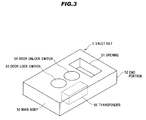
- FIG. 3 is a perspective view of the valet key storage device in the first preferred embodiment according to the present invention
- FIG. 4 is a block diagram of a vehicle control system in respect to the valet key storage device in the first preferred embodiment according to the present invention. A slashed portion of the valet key storage device 4 to a main body 40 is omitted below to facilitate visualization.
- the valet key storage device 4 is schematically configured to comprise an ECU 14 , a storage portion 42 as a valet key storage portion, a locking bar 44 and an actuator 45 as a driving section for driving the locking bar 44 .
- the valet key storage device 4 is schematically configured to comprise the main body 40 formed of a resin material or a metallic material in which the storage portion 42 and a concave portion 43 are formed, an antenna 41 provided near the storage portion 42 of the main body 40 for communicating with a regular key 3 and a valet key 5 , and the concave portion 43 for storing the actuator 45 .
- the concave portion 43 is communicated with the storage portion 42 .
- the storage portion 42 is in a rectangular shape and has a lower surface 42 a which is a surface parallel to a direction to insert the valet key 5 , namely, a direction indicated by an arrow D in shown FIG. 2 and a side surface 42 b which is a surface vertical to the arrow D direction, furthermore, the concave portion 43 is provided on the lower surface 42 a .
- the concave portion 43 is provided with an opening portion 43 a in which the locking bar 44 can be displaced freely insertable to the storage portion 42 and an attaching portion 43 b to which a below-described solenoid 45 a is installed.
- the locking bar 44 has, for example, a columnar shape, formed of a resin material or a metallic material and is configured to comprise a slant 44 a , a tip end 44 b and a concave portion 44 c .
- the slant 44 a is provided for storing the valet key 5 in the storage portion 42 smoothly by contacting with an end portion 52 of the valet key 5 and converting a force in the arrow D direction into a force in an arrow A direction when storing the valet key 5 in the storage portion 42 .
- the concave portion 44 c is provided so that a rod 45 b enters the concave portion 44 c when storing the valet key 5 in the storage portion 42 .
- the actuator 45 is schematically configured to comprise a solenoid 45 a for driving the rod 45 b using a non-illustrated magnetic body and a magnet coil, the rod(plunger rod) 45 b is connected with the locking bar 44 at one end portion, and a spring 45 c arranged around the rod 45 b for applying an elastic force to the locking bar 44 in an arrow B direction.
- the rod 45 b is configured to be stored inside the solenoid 45 a when the solenoid 45 a is driven in the arrow A direction and to be extended within the concave portion 44 c when driven in the arrow B direction to store the valet key 5 .
- the valet key 5 is schematically configured to comprise a main body 50 mounting electronic components such as a non-illustrated battery, a transponder 55 or the like, an opening 51 formed on the main body 50 and allowing a key holder, accessories or the like to be connected, the end portion 52 , a door lock switch 53 which is a button to lock a door of the vehicle 1 wirelessly, a door unlock switch 54 which is a button to unlock the door of the vehicle 1 wirelessly and the transponder 55 which communicates with a below-described ECU 14 via the antenna 41 .
- the valet key 5 in this preferred embodiment is a portable device not having a mechanical key, it may be a key type having a mechanical key, and it is not limited thereto.
- an opening provided in a conventional key may be diverted for use, in addition, it may be a concave portion not penetrating through the main body 50 to which the locking bar 44 is freely insertable, furthermore, it may be a configuration that the locking bar 44 enters the opening or the concave portion provided on the side surface of the valet key 5 and is coupled therewith, and it is not limited thereto.
- the transponder 55 is schematically configured to comprise a non-illustrated CPU (Central Processing Unit), a power supply circuit, a detector circuit, a memory unit to store an ID or the like. Furthermore, the transponder 55 communicates with the ECU 14 via the antenna 41 of the valet key storage device 4 in a predetermined period, and based on this communication, the ECU 14 verifies whether or not the valet key 5 is stored in the valet key storage device 4 .
- a non-illustrated CPU Central Processing Unit
- the ECU 14 verifies whether or not the valet key 5 is stored in the valet key storage device 4 .
- the ECU 14 controls the vehicle 1 so as not to accept any operations by the valet key 5 , namely, so as to invalidate the function of the valet key 5 .
- the ECU 14 invalidates a function of the valet key 5 when the valet key 5 is removed from the storage portion 42 in a non-valet mode.
- a vehicle control system 6 is schematically configured to comprise the regular key 3 having a button, a transponder and a mechanical key or the like which enable the locking or the unlocking of the door and allowing all operations using a key to the vehicle 1 to be conducted, the solenoid 45 a of the valet key storage device 4 , the valet key 5 , the engine switch 12 , the valet switch 13 , the ECU 14 , a door 15 , an engine 16 , the antenna 41 and an amplifier 41 a to amplify an electric wave received by the antenna 41 .
- the ECU 14 has an immobilizing function and is schematically configured to comprise a non-illustrated CPU, a power supply circuit, an ID authentication circuit, a memory unit to store an ID, or the like.
- a non-illustrated CPU a power supply circuit
- an ID authentication circuit a memory unit to store an ID, or the like.
- the ECU 14 sets up the mode of the vehicle 1 to be a valet mode and controls the startup/stop of the engine 16 and locking/unlocking of the door 15 of the vehicle 1 based on a signal transmitted from the engine switch 12 and an operational signal S 2 from the valet key 5 .
- the operational signal S 2 includes the ID of the valet key 5 .
- valet key storage device 4 Operation of the valet key storage device 4 in the first preferred embodiment will be explained in more detail in conjunction with each drawing.
- FIGS. 5A and 5B are cross sectional views of the valet key storage device in the first preferred embodiment according to the present invention, wherein FIG. 5A is before an ID certification and FIG. 5B is after the ID certification, and FIG. 6 is a cross sectional view of the valet key storage device in the first preferred embodiment according to the present invention when storing a valet key.
- the antenna 41 receives the ID certifying signal S 1 transmitted from the regular key 3 and the ECU 14 which receives the ID certifying signal S 1 via the antenna 41 and the amplifier 41 a certifies the ID of the regular key 3 and the ID of the vehicle 1 .
- the ECU 14 shifts a mode to the normal mode in which it is possible to start up or stop the engine 16 of the vehicle 1 .
- the ECU 14 starts the engine 16 controlling a non-illustrated ignition system.
- ECU 14 may drive the locking bar 44 via the solenoid 45 a and the rod 45 b , and release the lock of the valet key 5 .
- the driver After driving the vehicle 1 in the normal mode, as an example, the driver arrives at a hotel which is a destination and presses the valet switch 13 shown in FIG. 1 after stopping the engine 16 for depositing the vehicle 1 to a valet attendance of the hotel.
- the ECU 14 Since the ID of the regular key 3 matches the ID of the vehicle 1 , the ECU 14 , which received a signal from the valet switch 13 for shifting to the valet mode, shifts the mode of the vehicle 1 to the valet key system into the valet mode, furthermore, controls the actuator 45 of the valet key storage device 4 and displaces the locking bar 44 in the arrow A direction shown in FIG. 5A until the locking bar 44 comes out from the opening 51 of the valet key 5 . In the first preferred embodiment and the below-described second preferred embodiment, the ECU 14 controls the actuator 45 and displaces the locking bar 44 in the arrow B direction as shown in FIG.
- valet key 5 when the valet key 5 is taken out from the valet key storage device 4 and the vehicle 1 is operated, however, it is not limited thereto, it may be displaced in the arrow B direction after the valet key 5 is inserted into the storage portion 42 of the valet key storage device 4 , and it is not limited thereto, neither.
- the driver pulls out the valet key 5 in an arrow C direction shown in FIG. 5B holding a projecting portion 56 of the valet key 5 shown in FIG. 2 by hand, and passes the valet key 5 to the valet attendant.
- the valet attendant After receiving the valet key 5 from the driver, the valet attendant gets into the vehicle 1 and presses the engine switch 12 . Since the mode has been already shifted to the valet mode, the ECU 14 starts the engine 16 controlling the non-illustrated ignition system. The valet attendant drives the vehicle 1 and stops it at a predetermined space, then, the valet attendant stops the engine 16 by pushing down the engine switch 12 and pushes down the door lock switch 53 of the valet key 5 after getting off the vehicle. The valet key 5 transmits the operational signal S 2 to the vehicle 1 and the ECU 14 locks the door 15 of the vehicle 1 . Since the valet key 5 communicates with the ECU 14 via the antenna 41 and the amplifier 41 a in the predetermined period, it is not possible to start the engine 16 unless the valet key 5 is located at a position where the communication with the ECU 14 is possible.
- the driver receives the valet key 5 from the valet attendant for driving the vehicle 1 , gets into the vehicle 1 unlocking the door 15 by the regular key 3 or the valet key 5 and inserts the valet key 5 into the storage portion 42 of the valet key storage device 4 in the arrow D direction shown in FIG. 6 from the end portion 52 .
- the opening 51 of the valet key 5 does not contact with the slant 44 a of the locking bar 44 but does contact with a surface of the locking bar 44 vertical to the arrow C direction. Thus, it is not possible to pull out the valet key 5 .
- the valet mode is released by an operation of the driver, shifting to the normal mode.
- the operation by the valet key 5 is invalidated even if the valet key 5 can be pulled out in the normal mode.
- valet key 5 since the valet key 5 has the immobilizing function, it is possible to communicate with the vehicle 1 in the state that the valet key 5 is stored in the valet key storage device 4 .
- valet key storage device 4 since the valet key storage device 4 has the antenna 41 adjacent to the storage portion 42 , it is possible to certainly communicate with the stored valet key 5 .
- the immobilizing function is used for the communication with the valet key 5 , it is possible to invalidate the function of the valet key 5 based on the unauthorized withdrawal of the valet key 5 from the valet key storage device 4 .
- valet key 5 can be taken out from the valet key storage device 4 after realizing the certification of the ID of the regular key 3 and that of the vehicle 1 , it is possible to prevent the unauthorized withdrawal.
- a valet key storage device in the second preferred embodiment according to the present invention will be explained in more detail in conjunction with each drawing.
- the explanation for the portions which have the same structures and functions as the first preferred embodiment will be omitted by referring the mutual numbers in the following explanation.
- FIGS. 7A and 7B are cross sectional views of the valet key storage device in a second preferred embodiment according to the present invention, wherein FIG. 7A is before an ID certification and FIG. 7B is after the ID certification.
- a stopper 46 and a spring (an elastic member) 47 are newly provided compared with that of the first preferred embodiment.
- the stopper 46 is a plate-like member having a rectangular shape conformed to the shape of the storage portion 42 , in which the spring 47 shown in FIG. 7A is provided between a surface faced to the surface contacting with the end portion 52 of the valet key 5 and the side surface (bottom surface) 42 b .
- the spring 47 applies an elastic force to the stopper 46 in the arrow C direction.
- the ECU 14 which received a signal from the valet switch 13 for shifting to the valet mode, shifts the mode of the vehicle 1 to the valet mode, furthermore, controls the actuator 45 of the valet key storage device 4 and displaces the locking bar 44 in the arrow A direction shown in FIG. 7A until the locking bar 44 comes out from the opening 51 , namely, until the locking by the locking bar 44 is released.
- the valet key 5 Since the elastic force is applied by the spring 47 in the arrow C direction, the valet key 5 is slightly pushed out from the storage portion 42 when the locking bar 44 comes out from the opening 51 .
- the driver pulls out the valet key 5 holding the projecting portion 56 of the valet key 5 by hand, and then, passes it to the valet attendant.
- the driver receives the valet key 5 from the valet attendant for driving the vehicle 1 , gets into the vehicle 1 unlocking the door 15 by the regular key 3 or the valet key 5 and inserts the valet key 5 into the storage portion 42 of the valet key storage device 4 in the arrow D direction shown in FIG. 7B from the end portion 52 .
- the end portion 52 of the valet key 5 contacts with the slant 44 a of the locking bar 44 , the locking bar 44 is pushed in the arrow A direction and the rod 45 b is stored in the concave portion 44 c therewith. Furthermore, the locking bar 44 burrows into the lower surface of the valet key 5 shrinking the spring 45 c .
- the end portion 52 of the valet key 5 contacts with the stopper 46 , by which the spring 47 shrinks in the arrow D direction.
- valet key 5 since the valet key 5 is completely stored in the storage portion 42 , it is difficult to pull out the valet key 5 from the valet key storage device 4 when not being in the valet mode, thus, it is possible to store the valet key 5 in the vehicle 1 more securely.
Landscapes
- Engineering & Computer Science (AREA)
- Mechanical Engineering (AREA)
- Physics & Mathematics (AREA)
- Electromagnetism (AREA)
- Lock And Its Accessories (AREA)
- Vehicle Step Arrangements And Article Storage (AREA)
Abstract
Description
Claims (10)
Applications Claiming Priority (2)
| Application Number | Priority Date | Filing Date | Title |
|---|---|---|---|
| JP2007236752A JP4971083B2 (en) | 2007-09-12 | 2007-09-12 | Bullet key storage device |
| JP2007-236752 | 2007-09-12 |
Publications (2)
| Publication Number | Publication Date |
|---|---|
| US20090064740A1 US20090064740A1 (en) | 2009-03-12 |
| US8011214B2 true US8011214B2 (en) | 2011-09-06 |
Family
ID=40430401
Family Applications (1)
| Application Number | Title | Priority Date | Filing Date |
|---|---|---|---|
| US12/203,021 Expired - Fee Related US8011214B2 (en) | 2007-09-12 | 2008-09-02 | Valet key storage device |
Country Status (3)
| Country | Link |
|---|---|
| US (1) | US8011214B2 (en) |
| JP (1) | JP4971083B2 (en) |
| CN (1) | CN101386291B (en) |
Cited By (10)
| Publication number | Priority date | Publication date | Assignee | Title |
|---|---|---|---|---|
| US20090091421A1 (en) * | 2007-10-03 | 2009-04-09 | Kabushiki Kaisha Tokai Rika Denki Seisakusho | Valet key storage device |
| US20090309696A1 (en) * | 2008-06-12 | 2009-12-17 | Kabushiki Kaisha Tokai Rika Denki Seisakusho | Vehicle function restriction system |
| US20100071427A1 (en) * | 2008-09-24 | 2010-03-25 | Kabushiki Kaisha Tokai Rika Denki Seisakusho | Key slot device for in-vehicle auxiliary key |
| US20100073130A1 (en) * | 2008-09-24 | 2010-03-25 | Kabushiki Kaisha Tokai Rika Denki Seisakusho | Key holding device for in-vehicle auxiliary key |
| US20100090817A1 (en) * | 2008-10-14 | 2010-04-15 | Kabushiki Kaisha Tokai Rika Denki Seisakusho | Vehicle electronic key system |
| US20110040426A1 (en) * | 2009-08-17 | 2011-02-17 | Donna Long | Two step keyless start system |
| US20110219828A1 (en) * | 2010-03-12 | 2011-09-15 | Checkpoint Systems, Inc. | Security device |
| US8171764B2 (en) * | 2009-03-26 | 2012-05-08 | Panasonic Corporation | Electronic lock |
| US20200115931A1 (en) * | 2018-10-10 | 2020-04-16 | GM Global Technology Operations LLC | Vehicle key detection and storage |
| US11255107B2 (en) * | 2018-07-01 | 2022-02-22 | Joshua C. Ebreo | Key encasement having a combination lock |
Families Citing this family (4)
| Publication number | Priority date | Publication date | Assignee | Title |
|---|---|---|---|---|
| JP4971084B2 (en) * | 2007-09-12 | 2012-07-11 | 株式会社東海理化電機製作所 | Bullet key storage device |
| US8487743B2 (en) * | 2008-08-18 | 2013-07-16 | GM Global Technology Operations LLC | Valet keyfob system |
| EP2703236B1 (en) * | 2012-08-28 | 2016-05-18 | Robert Bosch Gmbh | An apparatus and method for restricting vehicle function |
| USD1049998S1 (en) * | 2022-09-08 | 2024-11-05 | Dr. Ing. H.C. F. Porsche Aktiengesellschaft | Interior control panel of motor vehicle |
Citations (19)
| Publication number | Priority date | Publication date | Assignee | Title |
|---|---|---|---|---|
| US3552160A (en) * | 1968-09-25 | 1971-01-05 | Alfred A Kleebauer | Key ejector locks |
| US3708032A (en) * | 1969-11-24 | 1973-01-02 | Tokai Rika Co Ltd | Accidental lock preventing device |
| US3851505A (en) * | 1973-05-01 | 1974-12-03 | L Wilkinson | Card holder for vehicles |
| US4318288A (en) * | 1979-04-30 | 1982-03-09 | Rifat Sultan A | Steering column lock |
| US4716748A (en) * | 1985-06-24 | 1988-01-05 | Nissan Motor Co., Ltd. | Steering lock device |
| US4898010A (en) * | 1987-10-28 | 1990-02-06 | Nissan Motor Company, Limited | Keyless entry system for automotive vehicles |
| US5254996A (en) * | 1990-11-29 | 1993-10-19 | Mercedes-Benz Ag | Charge monitoring system for a remote control system |
| US5714807A (en) * | 1996-04-18 | 1998-02-03 | Albanes; Pedro | Anti-theft lock for automotive vehicles which locks an automatic transmission |
| US6169650B1 (en) * | 1998-05-11 | 2001-01-02 | John M. Albrecht | Single access control system and method |
| US6546768B1 (en) * | 1998-08-28 | 2003-04-15 | Daimlerchrysler Ag | Ignition lock system for motor vehicles |
| US6756698B2 (en) * | 2000-04-04 | 2004-06-29 | Kabushiki Kaisha Tokai Rika Denki Seisakusho | Switch device for vehicle |
| US6776016B1 (en) * | 1999-08-21 | 2004-08-17 | Huf Hülsbeck & Fürst Gmbh & Co. Kg | Device for starting a motor vehicle motor, using an electronic key |
| JP2006225976A (en) | 2005-02-17 | 2006-08-31 | Mazda Motor Corp | Smart keyless system |
| US20080100418A1 (en) * | 2006-11-01 | 2008-05-01 | Anatoli Stobbe | Device for identifying and storing objects comprising identification carriers |
| US7392675B2 (en) * | 2002-11-08 | 2008-07-01 | Kabushiki Kaisha Tokai Rika Denki Seisakusho | Slot mechanism and smart ignition system |
| US20090091421A1 (en) * | 2007-10-03 | 2009-04-09 | Kabushiki Kaisha Tokai Rika Denki Seisakusho | Valet key storage device |
| US7581422B2 (en) * | 2004-04-21 | 2009-09-01 | Huf Hulsbeck & Furst Gmbh & Co. Kg | Device for starting a vehicle engine by means of an electronic key, and key to be used therefor |
| US7617708B2 (en) * | 2006-07-28 | 2009-11-17 | Volkswagen Ag | Ignition lock for a motor vehicle and method of operating an ignition lock system |
| US20100071427A1 (en) * | 2008-09-24 | 2010-03-25 | Kabushiki Kaisha Tokai Rika Denki Seisakusho | Key slot device for in-vehicle auxiliary key |
Family Cites Families (5)
| Publication number | Priority date | Publication date | Assignee | Title |
|---|---|---|---|---|
| JPH0311173U (en) * | 1989-06-19 | 1991-02-04 | ||
| JP2002120653A (en) * | 2000-10-18 | 2002-04-23 | Inoac Corp | Undercover with article storage part |
| JP4091406B2 (en) * | 2002-11-28 | 2008-05-28 | 株式会社東海理化電機製作所 | Vehicle key storage device |
| JP2005273211A (en) * | 2004-03-23 | 2005-10-06 | Denso Corp | Luggage-box locking device |
| JP2005306263A (en) * | 2004-04-23 | 2005-11-04 | Calsonic Kansei Corp | Portable device storage structure for vehicle |
-
2007
- 2007-09-12 JP JP2007236752A patent/JP4971083B2/en not_active Expired - Fee Related
-
2008
- 2008-09-02 US US12/203,021 patent/US8011214B2/en not_active Expired - Fee Related
- 2008-09-10 CN CN2008101495114A patent/CN101386291B/en not_active Expired - Fee Related
Patent Citations (19)
| Publication number | Priority date | Publication date | Assignee | Title |
|---|---|---|---|---|
| US3552160A (en) * | 1968-09-25 | 1971-01-05 | Alfred A Kleebauer | Key ejector locks |
| US3708032A (en) * | 1969-11-24 | 1973-01-02 | Tokai Rika Co Ltd | Accidental lock preventing device |
| US3851505A (en) * | 1973-05-01 | 1974-12-03 | L Wilkinson | Card holder for vehicles |
| US4318288A (en) * | 1979-04-30 | 1982-03-09 | Rifat Sultan A | Steering column lock |
| US4716748A (en) * | 1985-06-24 | 1988-01-05 | Nissan Motor Co., Ltd. | Steering lock device |
| US4898010A (en) * | 1987-10-28 | 1990-02-06 | Nissan Motor Company, Limited | Keyless entry system for automotive vehicles |
| US5254996A (en) * | 1990-11-29 | 1993-10-19 | Mercedes-Benz Ag | Charge monitoring system for a remote control system |
| US5714807A (en) * | 1996-04-18 | 1998-02-03 | Albanes; Pedro | Anti-theft lock for automotive vehicles which locks an automatic transmission |
| US6169650B1 (en) * | 1998-05-11 | 2001-01-02 | John M. Albrecht | Single access control system and method |
| US6546768B1 (en) * | 1998-08-28 | 2003-04-15 | Daimlerchrysler Ag | Ignition lock system for motor vehicles |
| US6776016B1 (en) * | 1999-08-21 | 2004-08-17 | Huf Hülsbeck & Fürst Gmbh & Co. Kg | Device for starting a motor vehicle motor, using an electronic key |
| US6756698B2 (en) * | 2000-04-04 | 2004-06-29 | Kabushiki Kaisha Tokai Rika Denki Seisakusho | Switch device for vehicle |
| US7392675B2 (en) * | 2002-11-08 | 2008-07-01 | Kabushiki Kaisha Tokai Rika Denki Seisakusho | Slot mechanism and smart ignition system |
| US7581422B2 (en) * | 2004-04-21 | 2009-09-01 | Huf Hulsbeck & Furst Gmbh & Co. Kg | Device for starting a vehicle engine by means of an electronic key, and key to be used therefor |
| JP2006225976A (en) | 2005-02-17 | 2006-08-31 | Mazda Motor Corp | Smart keyless system |
| US7617708B2 (en) * | 2006-07-28 | 2009-11-17 | Volkswagen Ag | Ignition lock for a motor vehicle and method of operating an ignition lock system |
| US20080100418A1 (en) * | 2006-11-01 | 2008-05-01 | Anatoli Stobbe | Device for identifying and storing objects comprising identification carriers |
| US20090091421A1 (en) * | 2007-10-03 | 2009-04-09 | Kabushiki Kaisha Tokai Rika Denki Seisakusho | Valet key storage device |
| US20100071427A1 (en) * | 2008-09-24 | 2010-03-25 | Kabushiki Kaisha Tokai Rika Denki Seisakusho | Key slot device for in-vehicle auxiliary key |
Cited By (25)
| Publication number | Priority date | Publication date | Assignee | Title |
|---|---|---|---|---|
| US20090091421A1 (en) * | 2007-10-03 | 2009-04-09 | Kabushiki Kaisha Tokai Rika Denki Seisakusho | Valet key storage device |
| US8138887B2 (en) * | 2007-10-03 | 2012-03-20 | Kabushiki Kaisha Tokai Rika Denki Seisakusho | Valet key storage device |
| US20090309696A1 (en) * | 2008-06-12 | 2009-12-17 | Kabushiki Kaisha Tokai Rika Denki Seisakusho | Vehicle function restriction system |
| US8487740B2 (en) * | 2008-06-12 | 2013-07-16 | Kabushiki Kaisha Tokai Rika Denki Seisakusho | Vehicle function restriction system |
| US8511121B2 (en) * | 2008-09-24 | 2013-08-20 | Kabushiki Kaisha Tokai Rika Denki Seisakusho | Key holding device for in-vehicle auxiliary key |
| US20100071427A1 (en) * | 2008-09-24 | 2010-03-25 | Kabushiki Kaisha Tokai Rika Denki Seisakusho | Key slot device for in-vehicle auxiliary key |
| US20100073130A1 (en) * | 2008-09-24 | 2010-03-25 | Kabushiki Kaisha Tokai Rika Denki Seisakusho | Key holding device for in-vehicle auxiliary key |
| US8648693B2 (en) * | 2008-09-24 | 2014-02-11 | Kabushiki Kaisha Tokai Rika Denki Seisakusho | Key slot device for in-vehicle auxiliary key |
| US20100090817A1 (en) * | 2008-10-14 | 2010-04-15 | Kabushiki Kaisha Tokai Rika Denki Seisakusho | Vehicle electronic key system |
| US8330571B2 (en) * | 2008-10-14 | 2012-12-11 | Kabushiki Kaisha Tokai Rika Denki Seisakusho | Vehicle electronic key system |
| US8171764B2 (en) * | 2009-03-26 | 2012-05-08 | Panasonic Corporation | Electronic lock |
| US10442397B2 (en) * | 2009-08-17 | 2019-10-15 | Donna Long | Two step smart key start system |
| US20110040426A1 (en) * | 2009-08-17 | 2011-02-17 | Donna Long | Two step keyless start system |
| US12570236B1 (en) * | 2009-08-17 | 2026-03-10 | Engle Grange, Llc | Vehicle movement restrictions premised on electronic keys |
| US20210316699A1 (en) * | 2009-08-17 | 2021-10-14 | Engle Grange, Llc | Two step smart key start system |
| US10077021B2 (en) * | 2009-08-17 | 2018-09-18 | Donna Long | Two step smart key start system |
| US10189441B2 (en) * | 2009-08-17 | 2019-01-29 | Donna Long | Two step smart key start system |
| US20190077369A1 (en) * | 2009-08-17 | 2019-03-14 | Donna Long | Two step smart key start system |
| US8548645B2 (en) * | 2009-08-17 | 2013-10-01 | Donna Long | Two step keyless start system |
| US20200001823A1 (en) * | 2009-08-17 | 2020-01-02 | Donna Long | Two step smart key start system |
| US10766454B2 (en) * | 2009-08-17 | 2020-09-08 | Engle Grange, Llc | Two step smart key start system |
| US8887541B2 (en) * | 2010-03-12 | 2014-11-18 | Checkpoint Systems, Inc. | Security device |
| US20110219828A1 (en) * | 2010-03-12 | 2011-09-15 | Checkpoint Systems, Inc. | Security device |
| US11255107B2 (en) * | 2018-07-01 | 2022-02-22 | Joshua C. Ebreo | Key encasement having a combination lock |
| US20200115931A1 (en) * | 2018-10-10 | 2020-04-16 | GM Global Technology Operations LLC | Vehicle key detection and storage |
Also Published As
| Publication number | Publication date |
|---|---|
| CN101386291A (en) | 2009-03-18 |
| JP4971083B2 (en) | 2012-07-11 |
| JP2009067189A (en) | 2009-04-02 |
| US20090064740A1 (en) | 2009-03-12 |
| CN101386291B (en) | 2011-07-20 |
Similar Documents
| Publication | Publication Date | Title |
|---|---|---|
| US8011214B2 (en) | Valet key storage device | |
| US7930915B2 (en) | Valet key storage device | |
| US8138887B2 (en) | Valet key storage device | |
| US20100071424A1 (en) | Electric lock for open-close body | |
| EP1903508B1 (en) | Key system | |
| US7956741B2 (en) | Tumbler type lock apparatus | |
| US8042367B2 (en) | Tumbler-type key verification system | |
| US20060266089A1 (en) | Hybrid key | |
| US7954347B2 (en) | Mechanical key code verification system | |
| JP5142389B2 (en) | Cylinder lock protector | |
| JP4555206B2 (en) | Electronic key for vehicle | |
| JP5880271B2 (en) | Vehicle control device | |
| US20090178447A1 (en) | Mechanical key code verification system | |
| JP2008254672A (en) | Engine start switch | |
| JP4355068B2 (en) | Electronic key device for vehicle | |
| KR20100079603A (en) | Smart key system and management method of the same | |
| JP2009262783A (en) | Portable machine storage system and portable machine | |
| JP2009287275A (en) | Electronic key and electronic key system | |
| JP2009264013A (en) | Locking device | |
| JP5142388B2 (en) | Cylinder lock protector | |
| JP4902410B2 (en) | Engine start switch | |
| JP5187943B2 (en) | Cylinder lock protector | |
| JP5172623B2 (en) | Key accommodation device | |
| KR20090117251A (en) | Key fob and trunk lid lock system | |
| JP2574335B2 (en) | Keyless load actuator for vehicles |
Legal Events
| Date | Code | Title | Description |
|---|---|---|---|
| AS | Assignment |
Owner name: KABUSHIKI KAISHA TOKAI RIKA DENKI SEISAKUSHO, JAPA Free format text: ASSIGNMENT OF ASSIGNORS INTEREST;ASSIGNORS:KATAGIRI, TOSHIHARU;SEKI, YOSHIYUKI;REEL/FRAME:021470/0773 Effective date: 20080822 |
|
| ZAAA | Notice of allowance and fees due |
Free format text: ORIGINAL CODE: NOA |
|
| ZAAB | Notice of allowance mailed |
Free format text: ORIGINAL CODE: MN/=. |
|
| STCF | Information on status: patent grant |
Free format text: PATENTED CASE |
|
| FEPP | Fee payment procedure |
Free format text: PAYOR NUMBER ASSIGNED (ORIGINAL EVENT CODE: ASPN); ENTITY STATUS OF PATENT OWNER: LARGE ENTITY |
|
| FPAY | Fee payment |
Year of fee payment: 4 |
|
| MAFP | Maintenance fee payment |
Free format text: PAYMENT OF MAINTENANCE FEE, 8TH YEAR, LARGE ENTITY (ORIGINAL EVENT CODE: M1552); ENTITY STATUS OF PATENT OWNER: LARGE ENTITY Year of fee payment: 8 |
|
| FEPP | Fee payment procedure |
Free format text: MAINTENANCE FEE REMINDER MAILED (ORIGINAL EVENT CODE: REM.); ENTITY STATUS OF PATENT OWNER: LARGE ENTITY |
|
| LAPS | Lapse for failure to pay maintenance fees |
Free format text: PATENT EXPIRED FOR FAILURE TO PAY MAINTENANCE FEES (ORIGINAL EVENT CODE: EXP.); ENTITY STATUS OF PATENT OWNER: LARGE ENTITY |
|
| STCH | Information on status: patent discontinuation |
Free format text: PATENT EXPIRED DUE TO NONPAYMENT OF MAINTENANCE FEES UNDER 37 CFR 1.362 |
|
| FP | Lapsed due to failure to pay maintenance fee |
Effective date: 20230906 |