US800981A - Air-blast attachment for dental engines. - Google Patents
Air-blast attachment for dental engines. Download PDFInfo
- Publication number
- US800981A US800981A US23055304A US1904230553A US800981A US 800981 A US800981 A US 800981A US 23055304 A US23055304 A US 23055304A US 1904230553 A US1904230553 A US 1904230553A US 800981 A US800981 A US 800981A
- Authority
- US
- United States
- Prior art keywords
- drill
- air
- fan
- casing
- shaft
- Prior art date
- Legal status (The legal status is an assumption and is not a legal conclusion. Google has not performed a legal analysis and makes no representation as to the accuracy of the status listed.)
- Expired - Lifetime
Links
Images
Classifications
-
- A—HUMAN NECESSITIES
- A61—MEDICAL OR VETERINARY SCIENCE; HYGIENE
- A61C—DENTISTRY; APPARATUS OR METHODS FOR ORAL OR DENTAL HYGIENE
- A61C1/00—Dental machines for boring or cutting ; General features of dental machines or apparatus, e.g. hand-piece design
- A61C1/02—Dental machines for boring or cutting ; General features of dental machines or apparatus, e.g. hand-piece design characterised by the drive of the dental tools
- A61C1/05—Dental machines for boring or cutting ; General features of dental machines or apparatus, e.g. hand-piece design characterised by the drive of the dental tools with turbine drive
- A61C1/052—Ducts for supplying driving or cooling fluid, e.g. air, water
Definitions
- This invention relates to air-blast attachments for dental engines.
- the object of the invention is to improve the construction of such attachments and to render them readily applicable to drill structures already in use without requiring any change in the structural arrangements of the latter.
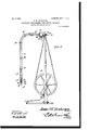
- Figure 1 is a view in elevation of an ordinary dental engine exhibiting the device of the present invention applied thereto.
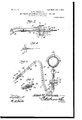
- Fig. 2 is a sectional detail view, on an enlarged scale, through the fan-casing shown in Fig. 1.
- Fig. 3 is a detail view, partly in section, exhibiting the fan-casing combined with an electric motor.
- Fig. 4 is a detached detail view of the form of fan used in connection with the embodiment of the invention exhibited in Fig. 3.
- Fig. 5 is a perspective detail View of the nozzle, showing the manner in which it is connected with the drill-stock.
- D designates an ordinary dental engine, (Z the drill-stock, and S the sheave incasing the flexible shaft 3. (Shown in Fig. 3.)
- S the sheave incasing the flexible shaft 3.
- the gist of the present invention resides in the novel form of fan attachment for supplying air at or near the point of a drill, thus to remove the chips and dust from the tooth being drilled as rapidly as made.
- This attachment as shown in the formv of embodiment of the invention exhibited in Figs. 1 and 2, comprises a shell or casing 1, having its rear side provided with air-inlet openings 2 and its front 3 connected with the shell by a threaded connection at a.
- This. shell is provided at its rear with a tubular internallythreaded extension 5, that is screwed upon an ordinary shaft-bearing 6, which, as usual, is adjustable to various angles, a slotted arm 7 and thumb-nut 8 being provided for this purpose.
- afan comprising a hub 9 and a plurality of blades 10, the hub having its terminal reduced to flt in bearings formed in the front and rear walls, as clearly shown in Fig. 2.
- the rigid extension 11 of the flexible shaft To the forward end of the hub is secured the rigid extension 11 of the flexible shaft, the rear end of the hub being provided with an extension 12, which fits in the bearing 6 and has secured to it the drive-sheave 18, the latter being secured to the fan extension 12 and the shaft 11 by a thumb bolt or screw 14, that passes through the hub of the sheave through the extension 12 and bites into the shaft 11.
- the front end or side of the shell is provided with a threaded boss 15, upon which is secured the end of the shaft-sheave 16, as clearly shown in Fig. 2.
- the front of the casing which, as before stated, is removable, is provided with a second tubular boss 17, to which is connected one end of a flexible pipe 18, the other end of whichcarries the blower-nozzle 19.
- a flexible pipe 18 is held combined with the sheave S through the medium of clamps or bands 20, of which there are shown, in this instance, four, although this number may be increased if found necessary or desirable.
- the blower-nozzle 19 comprises a tube 21, that is preferably tapered at one end and is disposed contiguous to the drill J2, and a sheath or collar 22, which is adapted to fit upon the outer end of the drill-stock and to beheld combined therewith through the medium of an angleslot 23, the locking portion 24 of the slot being designed to engage with a pin or stud 25, carried by the drill-stock.
- the rear end of the tube is provided with a flange 26, by which it is held combined with the tube 18 and with a stop-flange 27 in the nature of a disk, which is provided for the purpose of preventing the tube being pushed too far up upon the tube 21.
- the nozzle will be removed from the drill-stock and the pipe 18 from the tubular boss 17; but, if preferred, the attaclnnent may remain at all times combined with the drill mechanism.
- a dental engine the combination with the shaft-bearing, of a casing rigid therewith, a fan arranged within the casing and having a shank projecting through the bearing, a sheave mounted upon theshank, a drill-operating shaft projecting through the shank. means for clamping the sheave, the shank and shaft together, a blast-nozzle combined with the drill-stock, and a connection between the casing and the nozzle.
Landscapes
- Health & Medical Sciences (AREA)
- Oral & Maxillofacial Surgery (AREA)
- Dentistry (AREA)
- Epidemiology (AREA)
- Life Sciences & Earth Sciences (AREA)
- Animal Behavior & Ethology (AREA)
- General Health & Medical Sciences (AREA)
- Public Health (AREA)
- Veterinary Medicine (AREA)
- Dental Tools And Instruments Or Auxiliary Dental Instruments (AREA)
Description
PATENTED OCT. 3, 1905.
. BUCHANAN.
J. W AIR BLAST ATTAGHMENT FOR DENTAL ENGINES.
APPLICATION FILED OCT. 29. 1904.
2 SHEETS-SHEET 1.
fittomegs.
Witnesses a I No. 800,981. PATENTED OUT. 3, 1905. J. W. BUCHANAN.
AIR BLAST ATTACHMENT FOR DENTAL ENGINES APPLIOATION Hum 001: 29. 1904.
2 SHEETS-SHEET 2.
Witnesses:
JAMES TV. BUCHANAN, OF SAVANNAH, GEORGIA.
AIR-BLAST ATTACHMENT FOR DENTAL ENGINES.
Specification of Letters Patent.
Patented Oct. 3, 1905.
Application filed October 29,1904. Serial No 230.553.
f/o all whom it may concern.-
Be it known that 1, James W. BUCHANAN, a citizen of the United States, residing at Savannah, in the county of Chatham and State of Georgia, have invented a new and useful Air- Blast Attachment for Dental Engines,of which the following is a specification.
This invention relates to air-blast attachments for dental engines.
The object of the invention is to improve the construction of such attachments and to render them readily applicable to drill structures already in use without requiring any change in the structural arrangements of the latter.
With the above and other objects in View, as will appear as the nature of the invention is better understood, the same consists in the novel construction and combination of parts of an air-blast attachment for dental engines, as will be hereinafter fully described and claimed.
In the accompanying drawings, forming a part of this specification, and in which like characters of reference indicate corresponding parts, there are illustrated two forms of embodiment of the invention each capable of carrying the same into practical operation, it being understood that the elements therein ex hibited may be varied or changed as to shape, proportion, and exact manner of assemblage without departing from the spirit thereof.
In the drawings, Figure 1 is a view in elevation of an ordinary dental engine exhibiting the device of the present invention applied thereto. Fig. 2 is a sectional detail view, on an enlarged scale, through the fan-casing shown in Fig. 1. Fig. 3 is a detail view, partly in section, exhibiting the fan-casing combined with an electric motor. Fig. 4 is a detached detail view of the form of fan used in connection with the embodiment of the invention exhibited in Fig. 3. Fig. 5 is a perspective detail View of the nozzle, showing the manner in which it is connected with the drill-stock.
Referring to the drawings, D designates an ordinary dental engine, (Z the drill-stock, and S the sheave incasing the flexible shaft 3. (Shown in Fig. 3.) These parts may be of the usual or any preferred construction, and therefore need no detailed description.
The gist of the present invention resides in the novel form of fan attachment for supplying air at or near the point of a drill, thus to remove the chips and dust from the tooth being drilled as rapidly as made. This attachment, as shown in the formv of embodiment of the invention exhibited in Figs. 1 and 2, comprises a shell or casing 1, having its rear side provided with air-inlet openings 2 and its front 3 connected with the shell by a threaded connection at a. This. shell is provided at its rear with a tubular internallythreaded extension 5, that is screwed upon an ordinary shaft-bearing 6, which, as usual, is adjustable to various angles, a slotted arm 7 and thumb-nut 8 being provided for this purpose. Mounted within the shell is afan comprising a hub 9 and a plurality of blades 10, the hub having its terminal reduced to flt in bearings formed in the front and rear walls, as clearly shown in Fig. 2. To the forward end of the hub is secured the rigid extension 11 of the flexible shaft, the rear end of the hub being provided with an extension 12, which fits in the bearing 6 and has secured to it the drive-sheave 18, the latter being secured to the fan extension 12 and the shaft 11 by a thumb bolt or screw 14, that passes through the hub of the sheave through the extension 12 and bites into the shaft 11. The front end or side of the shell is provided with a threaded boss 15, upon which is secured the end of the shaft-sheave 16, as clearly shown in Fig. 2. The front of the casing, which, as before stated, is removable, is provided with a second tubular boss 17, to which is connected one end of a flexible pipe 18, the other end of whichcarries the blower-nozzle 19. (Clearly shown in Fig. The pipe 18 is held combined with the sheave S through the medium of clamps or bands 20, of which there are shown, in this instance, four, although this number may be increased if found necessary or desirable.
The blower-nozzle 19, to which reference has been made, comprises a tube 21, that is preferably tapered at one end and is disposed contiguous to the drill J2, and a sheath or collar 22, which is adapted to fit upon the outer end of the drill-stock and to beheld combined therewith through the medium of an angleslot 23, the locking portion 24 of the slot being designed to engage with a pin or stud 25, carried by the drill-stock. The rear end of the tube is provided with a flange 26, by which it is held combined with the tube 18 and with a stop-flange 27 in the nature of a disk, which is provided for the purpose of preventing the tube being pushed too far up upon the tube 21.
It will be seen from the description thus far given that when the sheave 13 is driven in the usual manner the fan will be rotated, and
through it the shaft which actuates the drill As the fan rotates air is drawn in through the inlets 2 and forced out through the tube 18 and out tl'lrough the nozzle and into the tooth in a plane approximately parallel with the drill. so that the dust and chips resulting from the drilling will be removed as rapidly as made. It will also be noted that the application of this invention to an ordinary dental drill will require no change in its structural arrangement, all the parts utilized in connecting the attachment with the drill being present in ordinary forms of drills in common use.
In the form of embodiment of the invention shown in Figs. 3 and 4: the only difference is that the fan-shank is screwed directly to the spindle m. of a motor M, which maybe any one of the overhead or suspended motors in common use, and therefore needs no detail description. When the spindle m is driven, motion is imparted to the fan -shank and thence to the flexible shaft s and from the latter to the drill, as usual.
In both forms of the invention when it is not desired to employ the blast attachment the nozzle will be removed from the drill-stock and the pipe 18 from the tubular boss 17; but, if preferred, the attaclnnent may remain at all times combined with the drill mechanism.
It will be seen from the foregoing description that although the improvements herein disclosed are simple in character they will in a ready and thoroughly-practical manner secure the objects designed and that the drilling out of teeth will be facilitated and the cut or drilled matter will be removed formed.
Having thus described the invention, what is claimed is 1. In a dental engine,a drill-operating shaft, a fan driven thereby, a casing housing the fan, and a discharge-nozzle communicating with the casing.
2. In a dental engine, the combination with a drill-operating shaft, of a fan carried thereby, a casing housing the fan, and a dischargenozzle in communication with the casing.
3. In a dental engine, the combination with the shaft-bearing, of a casing secured thereto, a fan arranged in the casing and having a hollow shank projecting through the bearing, a sheave mounted upon the shank, a drill-operating shaft projecting through the shank, and means for connecting the sheave, shank and operating-shaft.
4. In a dental engine, the combination with the shaft-bearing, of a casing rigid therewith, a fan arranged within the casing and having a shank projecting through the bearing, a sheave mounted upon theshank, a drill-operating shaft projecting through the shank. means for clamping the sheave, the shank and shaft together, a blast-nozzle combined with the drill-stock, and a connection between the casing and the nozzle.
In testimony that I claim the foregoing as my own I have hereto aflixed mysignature in the presence of two witnesses.
JAMES \V. BUCHANAN.
Witnesses:
FRED A. CLICK,
TuoMAs F. Realms.
Priority Applications (1)
| Application Number | Priority Date | Filing Date | Title |
|---|---|---|---|
| US23055304A US800981A (en) | 1904-10-29 | 1904-10-29 | Air-blast attachment for dental engines. |
Applications Claiming Priority (1)
| Application Number | Priority Date | Filing Date | Title |
|---|---|---|---|
| US23055304A US800981A (en) | 1904-10-29 | 1904-10-29 | Air-blast attachment for dental engines. |
Publications (1)
| Publication Number | Publication Date |
|---|---|
| US800981A true US800981A (en) | 1905-10-03 |
Family
ID=2869467
Family Applications (1)
| Application Number | Title | Priority Date | Filing Date |
|---|---|---|---|
| US23055304A Expired - Lifetime US800981A (en) | 1904-10-29 | 1904-10-29 | Air-blast attachment for dental engines. |
Country Status (1)
| Country | Link |
|---|---|
| US (1) | US800981A (en) |
-
1904
- 1904-10-29 US US23055304A patent/US800981A/en not_active Expired - Lifetime
Similar Documents
| Publication | Publication Date | Title |
|---|---|---|
| US3128988A (en) | Turbine driven air bearing dental handpiece | |
| US3120705A (en) | High-speed angle-handpieces for dental purposes | |
| JP5801335B2 (en) | Double fan hair dryer | |
| US2831295A (en) | Ultrasonic drill | |
| US800981A (en) | Air-blast attachment for dental engines. | |
| US4475889A (en) | Speed-increasing device for a dental handpiece | |
| US623469A (en) | Dental handpiece | |
| US3778904A (en) | Cooling system for a dental handpiece | |
| GB1342403A (en) | Hand-held percussive tools | |
| US20160184948A1 (en) | Foot attachment for pneumatic rotary tools | |
| US2387412A (en) | Toolhead or the like | |
| SE310234B (en) | ||
| GB410015A (en) | Improvements in or relating to high speed electrically driven portable dulling and like tools | |
| US3147551A (en) | Handpiece for dental drills or the like | |
| US3078576A (en) | High speed angle handpiece | |
| US1990036A (en) | Electric small tool | |
| USRE8231E (en) | Improvement in dental drills | |
| US184992A (en) | Improvement in hand-pieces for dental engines | |
| USRE6677E (en) | Improvement in dental engines | |
| US7758322B2 (en) | Fan system | |
| US274008A (en) | Dental-engine hand-piece | |
| JP3079541B2 (en) | Seal structure of rotary shaft device | |
| US2994129A (en) | High speed dental handpiece | |
| US980238A (en) | Fan attachment for dental engines. | |
| CN209856054U (en) | Handheld bladeless fan with high wind speed and low noise |