US8002497B2 - Coupler for leaching chamber systems - Google Patents
Coupler for leaching chamber systems Download PDFInfo
- Publication number
- US8002497B2 US8002497B2 US12/193,684 US19368408A US8002497B2 US 8002497 B2 US8002497 B2 US 8002497B2 US 19368408 A US19368408 A US 19368408A US 8002497 B2 US8002497 B2 US 8002497B2
- Authority
- US
- United States
- Prior art keywords
- coupler
- conduit
- end joint
- chamber
- leaching
- Prior art date
- Legal status (The legal status is an assumption and is not a legal conclusion. Google has not performed a legal analysis and makes no representation as to the accuracy of the status listed.)
- Expired - Fee Related
Links
Images


Classifications
-
- E—FIXED CONSTRUCTIONS
- E03—WATER SUPPLY; SEWERAGE
- E03F—SEWERS; CESSPOOLS
- E03F1/00—Methods, systems, or installations for draining-off sewage or storm water
- E03F1/002—Methods, systems, or installations for draining-off sewage or storm water with disposal into the ground, e.g. via dry wells
- E03F1/003—Methods, systems, or installations for draining-off sewage or storm water with disposal into the ground, e.g. via dry wells via underground elongated vaulted elements
Definitions
- Hollow plastic leaching chambers are commonly buried in the ground to form leaching fields for receiving and dispersing liquids such as sewage system effluent or storm water into the surrounding earth.
- Such leaching chambers have a central cavity for receiving liquids.
- An opening on the bottom and slots on the sides provide the means through which liquids are allowed to exit the central cavity and disperse into the surrounding earth.
- multiple leaching chambers are connected to each other in series to achieve a desired subterranean volume and dispersion area.
- Leaching chambers are usually arch-shaped and corrugated with symmetrical corrugations for strength. Additionally, leaching chambers usually come in standard sizes. The most common size for most leaching chambers is roughly six feet long, three feet wide and slightly over one foot high.
- the amount of liquid that a given leaching chamber is capable of receiving and dispersing is dependent upon the internal volume of the leaching chamber and the dispersion area over which the leaching chamber can disperse the liquids. Because most plastic leaching chambers are arch-shaped for strength, the volume and dispersion area for any given leaching chamber having the same dimensions is roughly the same. Therefore, most present leaching chambers of the same size have roughly the same capacity.
- the capacity of a leaching field depends upon the size and the number of leaching chambers employed. If the size or the number of the leaching chambers employed in a leaching field is increased, the volume and dispersion area is increased, thereby increasing capacity of the leaching field. However, increasing the size or the number of leaching chambers also increases the cost as well as the area of land required for burying the leaching chambers.
- Efficient use of the land can be increased by having the chambers follow the natural contours of the land.
- a leaching field When a leaching field is created from the chambers, they are typically installed with a slight downward slope away from the sewer inlet as mandated by local requirements. The elevation of the land, however, may change over the area of the leaching field.
- Arching and serpentine pathways can be created to generally follow the contours of the land and to avoid obstacles in the ground. For example, by deviating the pathway from a straight line, the chambers can be better installed at the proper grade while reducing the necessity to dig trenches deeper than necessary.
- Typical systems permit the pathway to turn, from one chamber to the next, by using a substantially fixed angle adapter between successive chambers.
- a coupler can connect a first leaching chamber and a second leaching chamber.
- the coupler can comprise a mating feature and an adjustment feature.
- the coupler can also directly connect to other couplers.
- the coupler can be a third leaching chamber, which can be a like chamber to the first and second chambers.
- the mating feature can be used to mate the coupler between the first leaching chamber and the second leaching chamber.
- the mating feature can include a swivel connector matable to an end of one of the chambers.
- the mating feature can also include a flange connector matable to an end of the other chamber.
- the adjustment feature can adjust the angle between the first chamber and the second chamber between a range of angles.
- the adjustment feature can include a swivel connector and the swivel connector can include a post member or a dome structure.
- the adjustment feature can be bidirectional to facilitate an adjustment in either the clockwise or counter-clockwise direction—as measured from the longitudinal direction of the connected chambers.
- the range of angles can be particularly chosen to be about 45°. More particularly, the range of angles can be about 22.5° in either direction.
- a more particular coupler can connect a first leaching chamber and a second leaching chamber, each chamber having a post interconnect and a dome interconnect at respective ends.
- the coupler can include a post member rotatably connectable with the dome interconnect of the first chamber and a connector for connecting to the post interconnect of the second chamber.
- the connector can be a flange, which can be a segmented flange.
- the connector can include a dome member rotatably connectable to the post interconnect of the second chamber.
- the connector can include a post member rotatably connectable to the post interconnect of the second chamber.
- a boss can also be used to define an adjustable range of angles between the first chamber and the second chamber.
- the boss can interface with the end of the first chamber to limit the adjustable angle the boss can be bidirectional to facilitate an adjustment either the clockwise or counter-clockwise direction.
- the range of angles can be about 45°. More specifically, the range of angles can be about 22.5° in either direction.
- FIG. 1 is a schematic diagram of a leaching chamber system employing adjustable couplers.
- FIGS. 2A-2C are foreshortened side views of chambers having a particular post and dome interconnect.
- FIG. 3 is a perspective view of a particular coupler of FIG. 1 .
- FIG. 4 is a perspective view of the coupler of FIG. 3 mated to a foreshortened leaching chamber.
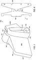
- FIG. 5 is a perspective view of a coupler for the post end of a leaching chamber.
- FIG. 6 is a perspective view of a first section of a swivel coupler assembly.
- FIG. 7 is a perspective view of a second section a swivel coupler assembly.
- FIG. 8 is a schematic diagram of the assembled swivel coupler sections of FIGS. 6 and 7 .
- FIG. 9 is a perspective view of an adjustable coupler insert.
- FIG. 10A-10B are schematic diagrams illustrated the use of the adjustable coupler insert of FIG. 9 .
- FIG. 1 is a schematic diagram of a leaching chamber system employing adjustable couplers.
- the system 1 includes a plurality of leaching chambers 10 A, 10 B, 10 C interconnected by a plurality of adjustable couplers 20 A, 20 B, 20 C to form a conduit.
- each coupler 20 A, 30 B, 20 C can deviate the linear path of the conduit by a respective bias angle ⁇ A , ⁇ B , ⁇ C .
- the bias angle for each coupler is bidirectionally adjustable within a range of angles in either the clockwise or counter-clockwise direction—as measured from the longitudinal direction of the connected chambers.
- a particular suitable range of angles is 0-22.5° in either direction—for a 45° range of motion.
- the couplers 20 can mate with chambers 10 or other couplers. By interconnecting multiple couplers 20 , the range of the turning angle can be multiplied. As shown the resulting angle ⁇ ⁇ from the second chamber 10 B to the third chamber 10 C is the sum of the respective bias angles, ⁇ B + ⁇ C , formed by the second and third couplers 20 B, 20 C.
- a particular chamber suitable for embodiments of the invention is described in U.S. Design Pat. No. 403,047 entitled “Post and Dome Interconnect for Leaching Chambers” issued to Gray on Dec. 22, 1998, the teachings of which are incorporated herein by reference in their entirety.
- each chamber 10 and couplers 20 are both conduits and that the coupler features can be integrally formed with the chambers.
- each chamber can have features of the adjustable coupler at one or both ends.
- the coupler can be another chamber like the adjacent chambers being interconnected.
- FIGS. 2A-2C are foreshortened side views of chambers having a particular post and dome interconnect. Shown are two identical chambers 10 , 10 ′, having complementary end flanges 130 , 130 ′.
- FIG. 2A shows a post end flange 130 , which includes a post interconnect 138 on a lower subarch 137 , a lower subarch flange segment 135 and an upper flange segment 131 , which can include structural webs (shown in phantom).
- FIG. 2B shows a dome end flange 130 ′, which includes a dome interconnect 139 , an upper subarch flange segment 136 , a lower top flange segment 133 , and an upper side flange segment 134 .
- FIG. 2C shows the two chambers 10 , 10 ′ interconnected by the flanges 130 , 130 ′.
- the dome interconnect 139 is manufactured to include a receptacle for receiving the post interconnect 138 .
- FIG. 3 is a perspective view of a particular coupler of FIG. 1 .
- the coupler 20 includes a swivel body 210 , an end transition 220 and a matable flange 230 . As shown, the coupler 20 is configured to mate with a post and dome interconnect.
- the swivel body 210 includes a top section 212 and left and right side sections 2146 L, 214 R.
- the top and side sections are dimensioned to be slidably rotatable within the interior of the mated chamber, as will be described below.
- a subarch dome section 216 is dimensioned to be slidably rotatable within the interior of the mated chamber subarch, as will also be described below.
- At the peak of the subarch dome 2176 is a circular post member 218 , which can mate with the interconnection dome 139 ( FIG. 2B ) of a chamber.
- the end transition 220 joins the swivel body 210 to the flange 230 . It includes left and right top sections 222 L, 222 R, left and right side sections 224 L, 224 R, and a subarch section 226 .
- the point of transition from the coupler body 210 is elevated to form a stop or boss on both the left and right sides 228 L, 228 R.
- the bosses 228 L, 228 R define the limits of the turn angle ⁇ in the left and right direction, respectively.
- the matable flange 230 is substantially identical to the dome end flange 130 ′ ( FIG. 2B ) of the chamber mated to by the post member 218 .
- the flange 230 includes a left and right upper top flange area 232 L, 232 R, a left and right lower top flange segments 233 L, 233 R, a left and right lower side flange segment 234 L, 234 R, and an upper subarch flange segment 236 .
- At the top of the upper subarch flange segment 236 is a dome interconnect 239 that has an empty interior substantially identical to the chamber dome interconnect 139 ( FIG. 2B ) for meeting with a post of a next chamber.
- FIG. 4 is a perspective view of the coupler of FIG. 3 mated to a foreshortened leaching chamber.
- the leaching chamber 10 is shown having a valley corrugation 110 and a peak corrugation 120 .
- a dome end mating flange 130 ′ is coupled to the coupler 20 .
- the resulting angle is to the right, limited by the right-side boss 228 R stopping the rotation of the chamber flange 130 ′ at its right lower top flange section 133 R.
- FIG. 5 is a perspective view of a coupler for the post end of a leaching chamber.
- the coupler 30 also includes a swivel body 310 , which slidably rotates under the chamber 10 ( FIG. 1 ).
- the coupler 30 interconnects with the post interconnect 138 ( FIG. 2A ) on the top of the chamber.
- an elevated circular dome coupler 339 is employed to mate with the chamber post interconnect.
- the coupler body 310 includes left and right top section 312 L, 312 R and side sections 314 L, 314 R dimensioned to fit and slidably rotate within the mated chamber, like the coupler 20 of FIGS. 2 and 3 .
- the coupler 30 includes a subarch dome 316 .
- a slit 317 separates the top of the subarch dome 136 from the dome coupler 319 .
- the coupler 30 includes a flange section 320 that matches the flange of the mated, post end of the chamber 10 .
- the flange 320 includes a lower subarch segment 327 , left and right upper top segments 322 L, 322 R, left and right lower side segments 325 L, 325 R.
- a post interconnect 328 At the top of the subarch 326 is a post interconnect 328 .
- the leaching chambers can include a tongue feature at the lower subarch flange segment 137 ( FIG. 2A ) of the post end flange 130 ( FIG. 2A ). When connected to the coupler 30 , the tongue can extend to or through the slit 317 to reduce or block the migration.
- the above slit problem can be eliminated if the leaching chambers are manufactured with a receptacle for receiving the post member 218 ( FIG. 2 ) under the chamber post connector 138 ( FIG. 2A ). In effect, there can be an indentation on the underside of the chamber and aligned with the center of the post connector. The relevant dimensions of the coupler could then be adjusted to mate with the post end of the chamber.
- FIGS. 6-8 illustrate a coupler assembly having a swivel joint for mating between chambers.
- FIG. 6 is a perspective view of a first section of a swivel coupler assembly.
- the first body 400 includes a floor 402 , a top 404 having a subarch feature 406 , and left and right walls 408 L, 408 R.
- the top 404 also forms flange segments 415 for mating with a specific chamber.
- the walls 408 L, 408 R terminate at curved webs 410 L, 410 R.
- An opening 420 is thereby created between the webs 410 L, 410 R.
- a circular post connector 422 is formed in the floor 402 and a circular dome 426 is formed at the subarch 406 .
- FIG. 7 is a perspective view of a second section a swivel coupler assembly.
- the second body 450 includes a top 454 having a subarch feature 456 and left and right walls 458 L, 458 R.
- the top 454 also forms flange segment 468 for mating with a specific chamber.
- the walls 458 L, 458 R terminate at a curved archway 460 .
- the archway includes a floor 462 having a circular hole 464 that is dimensional to fit around the post 422 of the first body 40 .
- a circular post 466 at the top of the archway 460 interconnects with the dome 426 of the first body 40 .
- the archway 460 defines an opening 470 .
- FIG. 8 is a schematic diagram of the assembled swivel coupler sections of FIGS. 6 and 7 .
- the curved webs 410 L, 410 R of the first body 400 cooperate with the shape of the archway 460 of the second body 450 to facilitate an angular adjustment between the coupler bodies 400 , 450 .
- Liquid can flow between chambers through the opening 470 of the archway 460 .
- the swivel coupler 40 can be employed with any leaching chamber system by altering the flange details.
- flanges include shiplap-type flanges as shown and described in U.S. Pat. No. 4,759,661 entitled “Leaching System Conduit,” which issued to Nichols et al. on Jul. 26, 1988; U.S. Design Pat. No. 329,684 entitled “Leaching Chamber,” which issued to Gray on Sep. 22, 1992; U.S. Pat. No. 5,156,488 entitled “Leaching System Conduit with Sub-Arch,” which issued to Nichols on Oct. 20, 1992; and U.S. Pat. No.
- a coupler for chambers having a post and dome interconnect could swivel about both the post interconnect and the dome interconnect of adjacent chambers.
- Such a coupler could replace the flange end of the coupler of FIG. 3 with the rotatable coupling, such as shown in FIG. 5 .
- FIG. 9 is a perspective view of an adjustable coupler insert.
- the coupler insert 50 includes peak corrugations 510 and valley corrugations 520 .
- the footprint of the coupler insert is in the shape of a segment of a toroid. That is, an inner base flange 530 is curved to have a first radius and an outer flange 540 is curved to have a second radius greater than the first radius.
- the result is a maximum relative turning angle ⁇ MAX , from end to end, of 45°.
- support gussets 515 connecting the peak corrugations to the outer flange 540 .
- FIG. 10A-10B are schematic diagrams illustrated the use of the adjustable coupler insert of FIG. 9 .
- the coupler insert 50 joins two chambers 10 D, 10 E.
- the turning angle between the chambers can be adjusted by sliding one or both chambers 10 D, 10 E over the coupler insert 50 until the desired angle ⁇ D , ⁇ E is achieved.
- the leaching chambers and couplers described herein can be prefabricated as a substantially rigid body from high density polyethylene (HDPE).
- the leaching chambers are fabricated from T60-800 HDPE.
- the wall thickness can be between 0.200 and 0.250 inches.
- the leaching chambers can be made of other suitable polymers or from other substantially rigid materials such as concrete, ceramics or metals.
Abstract
Description
Claims (28)
Priority Applications (1)
| Application Number | Priority Date | Filing Date | Title |
|---|---|---|---|
| US12/193,684 US8002497B2 (en) | 2000-09-15 | 2008-08-18 | Coupler for leaching chamber systems |
Applications Claiming Priority (4)
| Application Number | Priority Date | Filing Date | Title |
|---|---|---|---|
| US09/662,473 US6592293B1 (en) | 2000-09-15 | 2000-09-15 | Adjustable angle coupler for leaching chamber systems |
| US10/619,060 US7160059B2 (en) | 2000-09-15 | 2003-07-14 | Adjustable angle coupler for leaching chamber systems |
| US11/620,645 US7413382B2 (en) | 2000-09-15 | 2007-01-05 | Coupler for leaching chamber systems |
| US12/193,684 US8002497B2 (en) | 2000-09-15 | 2008-08-18 | Coupler for leaching chamber systems |
Related Parent Applications (1)
| Application Number | Title | Priority Date | Filing Date |
|---|---|---|---|
| US11/620,645 Continuation US7413382B2 (en) | 2000-09-15 | 2007-01-05 | Coupler for leaching chamber systems |
Publications (2)
| Publication Number | Publication Date |
|---|---|
| US20090180834A1 US20090180834A1 (en) | 2009-07-16 |
| US8002497B2 true US8002497B2 (en) | 2011-08-23 |
Family
ID=24657868
Family Applications (4)
| Application Number | Title | Priority Date | Filing Date |
|---|---|---|---|
| US09/662,473 Expired - Lifetime US6592293B1 (en) | 2000-09-15 | 2000-09-15 | Adjustable angle coupler for leaching chamber systems |
| US10/619,060 Expired - Lifetime US7160059B2 (en) | 2000-09-15 | 2003-07-14 | Adjustable angle coupler for leaching chamber systems |
| US11/620,645 Expired - Fee Related US7413382B2 (en) | 2000-09-15 | 2007-01-05 | Coupler for leaching chamber systems |
| US12/193,684 Expired - Fee Related US8002497B2 (en) | 2000-09-15 | 2008-08-18 | Coupler for leaching chamber systems |
Family Applications Before (3)
| Application Number | Title | Priority Date | Filing Date |
|---|---|---|---|
| US09/662,473 Expired - Lifetime US6592293B1 (en) | 2000-09-15 | 2000-09-15 | Adjustable angle coupler for leaching chamber systems |
| US10/619,060 Expired - Lifetime US7160059B2 (en) | 2000-09-15 | 2003-07-14 | Adjustable angle coupler for leaching chamber systems |
| US11/620,645 Expired - Fee Related US7413382B2 (en) | 2000-09-15 | 2007-01-05 | Coupler for leaching chamber systems |
Country Status (2)
| Country | Link |
|---|---|
| US (4) | US6592293B1 (en) |
| CA (1) | CA2357378C (en) |
Cited By (2)
| Publication number | Priority date | Publication date | Assignee | Title |
|---|---|---|---|---|
| US20110305513A1 (en) * | 2010-06-11 | 2011-12-15 | Ditullio Robert J | Riser Assembly for Water Storage Chambers |
| US11795679B2 (en) | 2021-07-19 | 2023-10-24 | Prinsco, Inc. | Asymmetric leaching chamber for onsite wastewater management system |
Families Citing this family (17)
| Publication number | Priority date | Publication date | Assignee | Title |
|---|---|---|---|---|
| US6592293B1 (en) * | 2000-09-15 | 2003-07-15 | Psa, Inc. | Adjustable angle coupler for leaching chamber systems |
| US7351006B2 (en) * | 2002-05-20 | 2008-04-01 | Infiltrator Systems, Inc. | Leaching chambers joined together with swivel connections |
| US7217063B2 (en) * | 2003-11-20 | 2007-05-15 | Infiltrator Systems, Inc. | Latch for leaching chamber |
| US7364384B1 (en) * | 2005-07-27 | 2008-04-29 | Infiltrator Systems, Inc. | Anti-rotation stop for chamber |
| WO2007021715A2 (en) * | 2005-08-10 | 2007-02-22 | Advanced Drainage Systems, Inc. | Arch-shaped corrugated leaching chamber |
| US7887256B2 (en) * | 2006-05-03 | 2011-02-15 | Joseph Miskovich | Smooth interior water collection and storage assembly |
| US7914231B2 (en) * | 2007-03-02 | 2011-03-29 | Infiltrator Systems, Inc. | Leaching chamber having a diagonally ribbed top |
| WO2008121890A1 (en) * | 2007-03-29 | 2008-10-09 | Rehbein Environmental Solutions, Inc. | Subsurface fluid distribution apparatus |
| US7955027B2 (en) * | 2008-09-08 | 2011-06-07 | National Diversified Sales, Inc. | System and method for a curved conduit |
| JP5555715B2 (en) * | 2009-11-30 | 2014-07-23 | 京セラ株式会社 | Control apparatus and control method |
| US9708807B2 (en) * | 2011-07-09 | 2017-07-18 | Joseph S. Miskovich | Water transfer device for underground water collection and storage chambers |
| US9739046B2 (en) | 2014-03-12 | 2017-08-22 | Joseph S. Miskovich | Modular stormwater retention and management system |
| US9371938B2 (en) | 2014-03-12 | 2016-06-21 | Joseph S. Miskovich | Modular construction conduit unit |
| US10597861B2 (en) | 2014-03-12 | 2020-03-24 | J.M. Sales Associates, Inc. | Modular stormwater retention system |
| USD840498S1 (en) | 2017-08-09 | 2019-02-12 | J.M. Sales Associates, Inc. | Modular fluid retention and management tray |
| US11867148B2 (en) | 2021-02-15 | 2024-01-09 | Trendsetter Vulcan Offshore, Inc. | Delivery of a high volume of floating systems for wind turbines |
| US11795629B2 (en) | 2022-01-13 | 2023-10-24 | National Diversified Sales, Inc. | Articulating channel |
Citations (4)
| Publication number | Priority date | Publication date | Assignee | Title |
|---|---|---|---|---|
| US5669733A (en) * | 1994-09-01 | 1997-09-23 | Hancor, Inc. | Angled adapter for a leaching chamber system |
| US6375388B1 (en) * | 2000-03-17 | 2002-04-23 | Zoeller Company | Affluent distribution system capable of being horizontally offset or curved |
| US6592293B1 (en) * | 2000-09-15 | 2003-07-15 | Psa, Inc. | Adjustable angle coupler for leaching chamber systems |
| US20030219310A1 (en) * | 2002-05-20 | 2003-11-27 | Burnes James J. | Leaching chambers joined together with swivel connections |
Family Cites Families (16)
| Publication number | Priority date | Publication date | Assignee | Title |
|---|---|---|---|---|
| US241465A (en) | 1881-05-10 | Samuel t | ||
| US77285A (en) | 1868-04-28 | holske | ||
| US1255023A (en) | 1916-04-22 | 1918-01-29 | Frederick W Lang | Joint-protector for sewer-pipes. |
| US1497549A (en) | 1922-03-06 | 1924-06-10 | Conradi Harry | Structural joint |
| US1541918A (en) | 1923-04-27 | 1925-06-16 | John W Brennan | Drainage tile |
| US1976628A (en) | 1929-10-24 | 1934-10-09 | John F O'rourke | Curved tunnel construction and method of producing same |
| US1873495A (en) | 1932-01-27 | 1932-08-23 | Walter R Smittle | Flexible pipe joint |
| US4305683A (en) | 1979-01-12 | 1981-12-15 | Harald Wagner | Tubular element for tunnel construction |
| US5215338A (en) | 1985-04-09 | 1993-06-01 | Tsubakimoto Chain Co. | Flexible supporting sheath for cables and the like |
| US4807370A (en) | 1987-07-06 | 1989-02-28 | Anterior, Inc. | Adjustable tube bending pattern device |
| US4783318A (en) * | 1987-10-02 | 1988-11-08 | The State Of Minnesota | Apparatus for environmental leaching testing |
| US4976288A (en) | 1989-06-22 | 1990-12-11 | Dynamic Air, Inc. | Tubing bend for pneumatic conveying system |
| US5588778A (en) * | 1995-05-19 | 1996-12-31 | Infiltrator Systems Inc. | Leaching chamber with angled end |
| US5829916A (en) * | 1995-06-05 | 1998-11-03 | Dixie Septic Tank, Inc. Of Orange City | Drainfield pipe |
| US6076993A (en) | 1997-06-16 | 2000-06-20 | Psa, Inc. | Leaching chamber |
| US5924821A (en) * | 1995-11-29 | 1999-07-20 | Landfill Technologies, Inc. | Apparatus and method for gas and/or liquid exchange between an area outside and an area inside a bulk material pile |
-
2000
- 2000-09-15 US US09/662,473 patent/US6592293B1/en not_active Expired - Lifetime
-
2001
- 2001-09-14 CA CA2357378A patent/CA2357378C/en not_active Expired - Fee Related
-
2003
- 2003-07-14 US US10/619,060 patent/US7160059B2/en not_active Expired - Lifetime
-
2007
- 2007-01-05 US US11/620,645 patent/US7413382B2/en not_active Expired - Fee Related
-
2008
- 2008-08-18 US US12/193,684 patent/US8002497B2/en not_active Expired - Fee Related
Patent Citations (10)
| Publication number | Priority date | Publication date | Assignee | Title |
|---|---|---|---|---|
| US5669733A (en) * | 1994-09-01 | 1997-09-23 | Hancor, Inc. | Angled adapter for a leaching chamber system |
| US6375388B1 (en) * | 2000-03-17 | 2002-04-23 | Zoeller Company | Affluent distribution system capable of being horizontally offset or curved |
| US6592293B1 (en) * | 2000-09-15 | 2003-07-15 | Psa, Inc. | Adjustable angle coupler for leaching chamber systems |
| US20040013469A1 (en) * | 2000-09-15 | 2004-01-22 | Psa, Inc. | Adjustable angle coupler for leaching chamber systems |
| US7160059B2 (en) * | 2000-09-15 | 2007-01-09 | Psa, Inc. | Adjustable angle coupler for leaching chamber systems |
| US20070196175A1 (en) * | 2000-09-15 | 2007-08-23 | Psa, Inc. | Coupler for leaching chamber systems |
| US7413382B2 (en) * | 2000-09-15 | 2008-08-19 | Psa, Inc. | Coupler for leaching chamber systems |
| US20030219310A1 (en) * | 2002-05-20 | 2003-11-27 | Burnes James J. | Leaching chambers joined together with swivel connections |
| US7351006B2 (en) * | 2002-05-20 | 2008-04-01 | Infiltrator Systems, Inc. | Leaching chambers joined together with swivel connections |
| US20080124177A1 (en) * | 2002-05-20 | 2008-05-29 | Burnes James J | Leaching chambers joined together with swivel connections |
Cited By (3)
| Publication number | Priority date | Publication date | Assignee | Title |
|---|---|---|---|---|
| US20110305513A1 (en) * | 2010-06-11 | 2011-12-15 | Ditullio Robert J | Riser Assembly for Water Storage Chambers |
| US8414222B2 (en) * | 2010-06-11 | 2013-04-09 | Robert J. DiTullio | Riser assembly for water storage chambers |
| US11795679B2 (en) | 2021-07-19 | 2023-10-24 | Prinsco, Inc. | Asymmetric leaching chamber for onsite wastewater management system |
Also Published As
| Publication number | Publication date |
|---|---|
| US7413382B2 (en) | 2008-08-19 |
| US20040013469A1 (en) | 2004-01-22 |
| CA2357378A1 (en) | 2002-03-15 |
| US20070196175A1 (en) | 2007-08-23 |
| US6592293B1 (en) | 2003-07-15 |
| US20090180834A1 (en) | 2009-07-16 |
| CA2357378C (en) | 2010-11-30 |
| US7160059B2 (en) | 2007-01-09 |
Similar Documents
| Publication | Publication Date | Title |
|---|---|---|
| US8002497B2 (en) | Coupler for leaching chamber systems | |
| US6076993A (en) | Leaching chamber | |
| US3926222A (en) | Corrugated tubing with integral coupling means thereon | |
| US8337119B2 (en) | Leaching chamber having a dome shaped end portion for pivotably connecting with a second chamber end portion | |
| US5588778A (en) | Leaching chamber with angled end | |
| AU719891B2 (en) | Storm water dispersing system having multiple arches | |
| US3699684A (en) | Corrugated drainage tubes and fittings | |
| US5669733A (en) | Angled adapter for a leaching chamber system | |
| US6273640B1 (en) | Irrigation ditch liner | |
| US5836716A (en) | Drainage pipe | |
| US9297135B2 (en) | Structural lining system | |
| US5890837A (en) | Multiple compartment drainage conduit with diverters | |
| US4483643A (en) | Canal bed shell | |
| US20040253054A1 (en) | Effluent distribution system | |
| CA2176074C (en) | Flumes for manhole inverts | |
| US6968854B2 (en) | Manhole base | |
| US11795679B2 (en) | Asymmetric leaching chamber for onsite wastewater management system | |
| JP2656905B2 (en) | Gutter made of synthetic resin | |
| GB2174472A (en) | Pipe with longitudinal joints | |
| US20240117621A1 (en) | Universal base plate with tabs | |
| AP900A (en) | Pipe fitting. | |
| JPH11193560A (en) | Drain pipe joint | |
| RU15899U1 (en) | MULTI-SECTION PASSING WELL | |
| JP2530149Y2 (en) | PVC small diameter manhole for step joining | |
| JP3495785B2 (en) | Quantitative water diversion system for intake or sewer system |
Legal Events
| Date | Code | Title | Description |
|---|---|---|---|
| ZAAA | Notice of allowance and fees due |
Free format text: ORIGINAL CODE: NOA |
|
| ZAAB | Notice of allowance mailed |
Free format text: ORIGINAL CODE: MN/=. |
|
| REMI | Maintenance fee reminder mailed | ||
| AS | Assignment |
Owner name: DEUTSCHE BANK AG NEW YORK BRANCH, NEW YORK Free format text: SECURITY INTEREST;ASSIGNORS:ISI POLYETHYLENE SOLUTIONS, LLC;EZFLOW, L.P.;INFILTRATOR WATER TECHNOLOGIES, LLC;REEL/FRAME:036044/0562 Effective date: 20150527 Owner name: DEUTSCHE BANK AG NEW YORK BRANCH, NEW YORK Free format text: SECURITY INTEREST;ASSIGNORS:ISI POLYETHYLENE SOLUTIONS, LLC;EZFLOW, L.P.;INFILTRATOR WATER TECHNOLOGIES, LLC;REEL/FRAME:036044/0627 Effective date: 20150527 |
|
| LAPS | Lapse for failure to pay maintenance fees | ||
| REIN | Reinstatement after maintenance fee payment confirmed | ||
| FP | Lapsed due to failure to pay maintenance fee |
Effective date: 20150823 |
|
| FEPP | Fee payment procedure |
Free format text: PETITION RELATED TO MAINTENANCE FEES FILED (ORIGINAL EVENT CODE: PMFP); ENTITY STATUS OF PATENT OWNER: LARGE ENTITY |
|
| AS | Assignment |
Owner name: ISI POLYETHYLENE SOLUTIONS, LLC, CONNECTICUT Free format text: ASSIGNMENT OF ASSIGNORS INTEREST;ASSIGNOR:PSA, INC;REEL/FRAME:039538/0456 Effective date: 20120112 |
|
| FPAY | Fee payment |
Year of fee payment: 4 |
|
| SULP | Surcharge for late payment | ||
| FEPP | Fee payment procedure |
Free format text: PETITION RELATED TO MAINTENANCE FEES GRANTED (ORIGINAL EVENT CODE: PMFG); ENTITY STATUS OF PATENT OWNER: LARGE ENTITY |
|
| AS | Assignment |
Owner name: ISI POLYETHYLENE SOLUTIONS, LLC, CONNECTICUT Free format text: RELEASE BY SECURED PARTY;ASSIGNOR:DEUTSCHE BANK AG NEW YORK;REEL/FRAME:041777/0638 Effective date: 20170217 Owner name: INFILTRATOR WATER TECHNOLOGIES, LLC, CONNECTICUT Free format text: RELEASE BY SECURED PARTY;ASSIGNOR:DEUTSCHE BANK AG NEW YORK;REEL/FRAME:041777/0638 Effective date: 20170217 Owner name: EZFLOW, L.P., CONNECTICUT Free format text: RELEASE BY SECURED PARTY;ASSIGNOR:DEUTSCHE BANK AG NEW YORK;REEL/FRAME:041777/0638 Effective date: 20170217 |
|
| PRDP | Patent reinstated due to the acceptance of a late maintenance fee |
Effective date: 20170815 |
|
| STCF | Information on status: patent grant |
Free format text: PATENTED CASE |
|
| FEPP | Fee payment procedure |
Free format text: 7.5 YR SURCHARGE - LATE PMT W/IN 6 MO, LARGE ENTITY (ORIGINAL EVENT CODE: M1555); ENTITY STATUS OF PATENT OWNER: LARGE ENTITY |
|
| MAFP | Maintenance fee payment |
Free format text: PAYMENT OF MAINTENANCE FEE, 8TH YEAR, LARGE ENTITY (ORIGINAL EVENT CODE: M1552); ENTITY STATUS OF PATENT OWNER: LARGE ENTITY Year of fee payment: 8 |
|
| AS | Assignment |
Owner name: ISI POLYETHYLENE SOLUTIONS, LLC, CONNECTICUT Free format text: RELEASE OF SECURITY INTERESTS IN PATENTS (RELEASES RF 036044/0562);ASSIGNOR:DEUTSCHE BANK AG NEW YORK BRANCH, AS COLLATERAL AGENT;REEL/FRAME:049942/0332 Effective date: 20190731 Owner name: EZFLOW, L.P., CONNECTICUT Free format text: RELEASE OF SECURITY INTERESTS IN PATENTS (RELEASES RF 036044/0562);ASSIGNOR:DEUTSCHE BANK AG NEW YORK BRANCH, AS COLLATERAL AGENT;REEL/FRAME:049942/0332 Effective date: 20190731 Owner name: INFILTRATOR WATER TECHNOLOGIES, LLC, CONNECTICUT Free format text: RELEASE OF SECURITY INTERESTS IN PATENTS (RELEASES RF 036044/0562);ASSIGNOR:DEUTSCHE BANK AG NEW YORK BRANCH, AS COLLATERAL AGENT;REEL/FRAME:049942/0332 Effective date: 20190731 |
|
| FEPP | Fee payment procedure |
Free format text: MAINTENANCE FEE REMINDER MAILED (ORIGINAL EVENT CODE: REM.); ENTITY STATUS OF PATENT OWNER: LARGE ENTITY |
|
| LAPS | Lapse for failure to pay maintenance fees |
Free format text: PATENT EXPIRED FOR FAILURE TO PAY MAINTENANCE FEES (ORIGINAL EVENT CODE: EXP.); ENTITY STATUS OF PATENT OWNER: LARGE ENTITY |
|
| STCH | Information on status: patent discontinuation |
Free format text: PATENT EXPIRED DUE TO NONPAYMENT OF MAINTENANCE FEES UNDER 37 CFR 1.362 |
|
| FP | Lapsed due to failure to pay maintenance fee |
Effective date: 20230823 |