US8000586B2 - Video player - Google Patents
Video player Download PDFInfo
- Publication number
- US8000586B2 US8000586B2 US11/222,044 US22204405A US8000586B2 US 8000586 B2 US8000586 B2 US 8000586B2 US 22204405 A US22204405 A US 22204405A US 8000586 B2 US8000586 B2 US 8000586B2
- Authority
- US
- United States
- Prior art keywords
- video
- computer
- audio
- signals
- video player
- Prior art date
- Legal status (The legal status is an assumption and is not a legal conclusion. Google has not performed a legal analysis and makes no representation as to the accuracy of the status listed.)
- Expired - Fee Related, expires
Links
Images


Classifications
-
- H—ELECTRICITY
- H04—ELECTRIC COMMUNICATION TECHNIQUE
- H04N—PICTORIAL COMMUNICATION, e.g. TELEVISION
- H04N5/00—Details of television systems
- H04N5/76—Television signal recording
- H04N5/84—Television signal recording using optical recording
- H04N5/85—Television signal recording using optical recording on discs or drums
-
- H—ELECTRICITY
- H04—ELECTRIC COMMUNICATION TECHNIQUE
- H04N—PICTORIAL COMMUNICATION, e.g. TELEVISION
- H04N5/00—Details of television systems
- H04N5/76—Television signal recording
- H04N5/765—Interface circuits between an apparatus for recording and another apparatus
-
- H—ELECTRICITY
- H04—ELECTRIC COMMUNICATION TECHNIQUE
- H04N—PICTORIAL COMMUNICATION, e.g. TELEVISION
- H04N5/00—Details of television systems
- H04N5/76—Television signal recording
- H04N5/765—Interface circuits between an apparatus for recording and another apparatus
- H04N5/775—Interface circuits between an apparatus for recording and another apparatus between a recording apparatus and a television receiver
Definitions
- the present invention relates to a video player capable of sharing an optical disc driver with a PC, in particular, to a video player playing multimedia when the PC is shut off.
- the object of the present invention is to provide a video player capable of playing video medium independently with the PC's assistance under the state of PC's power off.
- the video player of the present invention comprises: a decoding and control unit for receiving video and audio signals and then outputting decoded video and audio signals functioned by a control command; a storing unit for storing an application software capable of working without starting the computer operation system; a video processing unit for processing decoded video signals outputted by the decoding and control unit and outputting the decoded video signals to a display after processing without starting the computer operation system; an audio processing unit for processing decoded audio signals outputted by the decoding and control unit and outputting the decoded audio signals to a sound box after processing without starting the computer operation system; an Optical disc driver's multi-use control circuit for multi-use controlling the Optical disc driver of the computer; and a switch unit for switching the video processing unit and the audio processing unit to be coupled respectively to the display and the sound box after monitoring a shut-off signal of the computer, and in the meantime switching two outputs of DC power to the video player.
- the storing unit of the video player comprises a SDRAM for storing temporary data and instruction transferred when processing application program; an EEPROM for storing the related information of producer; and a FLASH for storing the main program and instruction sets of video player.
- the decoding and control unit comprises a 32-bit main controlling IC chip.
- the switch unit comprises a plurality of relays for controlling multi-way on-off switches respectively, the feeder ear of the relay connects with DC power and the earth terminal connects in series with an electric switch which is on or off under the effect of control signals.
- the present invention plays video of multimedia products with making the best of hardware sources of PC by using a unique switch unit to monitor the shut-off signal and then switch under the PC's power off condition, therefore avoids adding new operation program. And the present invention has reasonable structures and novel principles which satisfy the market.
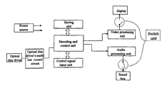
- FIG. 1 is a structural drawing of the video player of the present invention
- FIG. 2 is a schematic drawing of switching between the video player and PC
- FIG. 3 is a schematic drawing of tri-state multi-use controlling principle of an Optical disc driver
- FIG. 4 is a circuit diagram of the switch unit
- FIG. 5 is a schematic drawing of another tri-state multi-use controlling principle of Optical disc driver
- FIG. 6 is a module drawing of another embodiment of the video switch member
- FIG. 7 is a module drawing of another embodiment of the audio switches member.
- the video player of the present invention is used to work together with PC. Under the state of PC's power off, we can use some hardware sources such as Optical disc driver, screen display, and sound box, to play video medium of multimedia products.
- the structure of the video player comprises a decoding and control unit, a storing unit, a video processing unit, an audio processing unit, an Optical disc driver's multi-use control circuit and a switch unit.
- the decoding and control unit for receiving video and audio signals and outputting decoding the signals functioned by the control instruction; the receiving video and audio signals are got by reading the Optical disc driver.
- the control instruction can be input through pressing keys on the front panel of the video player or by a remote manipulator.
- the decoding and control unit adopts ALI M3325 main chip, a 32-bit main controlling IC chip.
- the present invention needs to play video medium under the state of PC's power off, therefore the playing software, for processing playing after the input signals decoded by the decoding and control unit, should be pre-stored in the storing unit.
- the storing unit of the video player comprises: a SDRAM for storing temporary data and instruction transferred when processing application program; an EEPROM for storing the related information of producer; and a FLASH for storing the main program and instruction sets of the video player.
- the video processing unit for processing decoded video signals outputted by the decoding and control unit and outputting the decoded video signals to a display after processing without starting the computer operation system;
- the audio processing unit for processing decoded audio signals outputted by the decoding and control unit and outputting the decoded video signals to a sound box after processing without starting the computer operation system;
- the Optical disc driver's multi-use control circuit for multi-use controlling an Optical disc driver of the computer
- the switch unit switches the video processing unit and the audio processing unit to be coupled respectively to the display and the sound box, after monitoring a shut-off signal of the computer, and in the meantime switching two outputs of DC power to the video player.
- the switch unit switches the audio processing unit and the video processing unit to the screen display and sound box of the computer side.
- the Optical disc driver is a sub-device of the computer system in the present invention.
- the switch unit monitors the shut-off signal of the computer, the Optical disc driver is used as a sub-device of the video player of the present invention.
- the Optical disc driver also needs the switch unit to switch basing on the monitored signal.
- the power source of the Optical disc driver is supplied by a plus 5V of a special power supply.
- the power source will be kept on supplying for the Optical disc driver whenever the computer is on or off until the video player is shut off. Therefore, the foregoing realizes a time dividing and multi-use control of the optical disc driver.
- the switch unit cuts off the video player to be out of work.
- the switch unit When the computer is shut off normally, the switch unit begins switching to start up the decoding and control unit of the video player and at the same time the video processing unit and the audio processing unit are switched to the state of working.
- the signal controlling input unit of the video player receives the controlling signals from key-pressing or remote controlling, the main chip ALI M3325 reads the MPEG-1, MPEG-2 data of the DVD driver and decodes them by IDE interface. And after the signals are amplified by the video and audio processing units, the video and audio signals are transmitted to the sound box and the display to be played respectively.
- FIG. 2 is a schematic drawing of switching between the video player and PC of the present invention.
- the video player of the present invention contains three interfaces, which can be chosen to switch by the means of one as in two so that the Optical disc driver can be multi-used by the video player and PC.
- Showing in FIG. 1 The connection between the video processing unit and the screen display involves six circuit lines respectively representing R, G, B, H, V and ground signals.
- the connection between the audio processing unit and the sound box involves 7 circuit lines respectively representing left and right sound channels from audio channel 1 to audio channel 3 , ground line and data and control signal line from IDE data line of the video player to DVD driver. All these lines will be switched by the means of one as in two of the switch unit or the Optical disc driver's multi-use control circuit.
- FIG. 3 shows a schematic drawing of the multi-use DVD driver, using a tri-state control circuit to multi-use control.
- the tri-state control circuit adopts 74HC 126 chip which has four tri-state control outputs.
- the computer and the video player are the main devices, and the Optical disc driver is the sub-device. Due to using the above controlling, only one main device is allowed to operate the Optical disc driver at anytime, which guarantees the exclusiveness and reliability of the operation.
- FIG. 4 shows the circuit diagram of the switch unit. It can be seen in FIG. 4 that the switch unit consists of a plurality of super small relays; every relay has four groups of on-off, each group has two-way trigger points.
- the feeder ear of the relay is connected to the positive 5v voltage and the ground terminal is connected to the electric switch mainly consisting of dynatrons in series.
- the constructer principle of switch part between the video part and the power sources in the switch unit is described as follows: setting two relays upper and lower, type of SPDT, each relay respectively controls four groups of on-off and each group has two trigger points.
- the switch part between the video and the power sources showing in FIG. 4 the four groups of on-off of the upper relay respectively correspond to signals R, G, B and H, and the first way trigger point of every group is connected to the personal computer side, the second way is connected to the video player side to ensure synchronized switching.
- Three groups of the four groups of on-off of the lower relay are used.
- the first group corresponds to signal V and the first way trigger point is connected to the PC side and the second way is connected to the decoding and control unit side.
- the second group is empty.
- the third group corresponds to DC+5v.
- the first way trigger point of the third group is empty, and the second way is connected to positive 5v of the video player for supplying the power for main controlling chip M3325 and other peripheral circuitry of the video player (e.g.+5v in FIG. 3 connected to foot 1 and foot 4 , Please refer to FIG. 3 ).
- the first way of the forth group is empty and the second way is connected to positive 12v voltage for supplying power for an audio operation amplifier chip OPA4558 of the audio processing unit.
- the collector of the dynatron of the electric switch is coupled to the earth terminal of the relay, an emitter of the dynatron is coupled to the ground, and a resistance R 7 is connected between the base electrode and the emitter, besides, the base electrode couples to one end of a resistance R 1 , and another end of the R 1 couples to a cathode of a diode for receiving switch signals.
- feeder ear and the earth terminal of the relay connect with a diode and the cathode of the diode couples to the feeder ear.
- the principle of the audio switch is the same as the foregoing principle. Also uses two relays type of SPDF of upper and lower relay. Each relay controls four groups of on-off respectively and each group has two trigger points. The switch part between the audio and the power source showing in FIG. 3 , only three groups of on-off of the upper relay are used.
- the first way trigger point of each group is connected to the PC side, the second way is connected to the video player side to ensure synchronized switching.
- the first group corresponds to the left channel of audio channel 1
- the second one corresponds to the right channel of audio channel 1
- the third one is empty
- the forth one corresponds to the left channel of audio channel 2 . Only three groups of on-off of the lower relay are used.
- the first way trigger point of each group is connected to the PC side. And the second way is connected to the video player side.
- the first group corresponds to the right channel of audio channel 2
- the second one is empty
- the third one corresponds to the left channel of audio channel 3
- the forth one corresponds to the right channel of audio channel 3 .
- the action of switching and controlling is triggered by the signal of power on or off, which is monitored by the electric switch mainly consisting of dynatron.
- the slot I of the computer When the computer is power-on, the slot I of the computer outputs positive 5v voltage. Said voltage is sent to the base electrode to electrify the dynatron so that the relay can work with normal power, and switch the display and the sound box to the computer side so that the computer controls the Optical disc driver to play the video medium;
- the output of the positive 5v voltage of the slot I of the computer disappears, thus the dynatron is under the state of being shut off and the relay's power supplying circuit is cut off so as to switch the second way trigger point to the video player side.
- the second way trigger point Providing that the computer is under the state of power-off, the second way trigger point is always switched to the video player side.
- the collector of the dynatron of the electric switch is coupled to the earth terminal of the relay, an emitter of the dynatron is coupled to the ground, and a resistance R 7 is connected between the base electrode and the emitter, besides, the base electrode couples to one end of a resistance R 1 , and another end of the R 1 couples to a cathode of a diode for receiving switch signals.
- the Optical disc driver's multi-use control circuit of the present invention can be performed by another form of a tri-state circuit.
- the tri-state circuit can control the DVD driver coupled to the PC main board side or the video player side alternatively.
- the tri-state circuit consists of the 74HC4053 chips.
- a plurality of 74HC4053 chips connect to DVD driver's pins, IDE data line of the PC's main board and IDE data line of the decoding and control unit of the video player, and through the 74HC4053 chips, the signals sent out by the DVD driver are switched to the PC main board or the decoding and control unit of the video player.
- PC main board's MB — +5v is an effective voltage, simultaneity, the positive 5v of the video player are null. So the power supplied to the video player is null, and the control end of the 74HC4053 chip is on high tension, therefore the Optical disc driver is ducting with the IDE data line of the PC main board, and signals are sent to PC main board through the IDE interface.
- PC main board's MB — +5v is null. So the power supplied to the PC main board is null, simultaneity, the positive 5v switched to the video player is effective, i.e. supplying power to the decoding and control unit of the video player.
- the control end of the 74HC4053 chip is on low tension.
- the Optical disc driver is closed with the IDE data line of the PC main board and is ducting with the IDE data line of the decoding and control unit of the video player. Signals are transmitted to the decoding and control unit of the video player through the IDE interface.
- control circuit for controlling the multi-use of the Optical disc driver in this embodiment can use other means of controlling circuit.
- FIG. 6 illustrates the module drawing of the video switching member.
- the change-over switch is made of QS3384 chip, coupled to computer display.
- the PC video card and the video processing unit of the video player may be connected to QS3384 alternatively.
- the QS3384 chip is switched to the PC's video card side coupled to computer display via a tension controlling. Therefore, the video signals are provided to the computer display by PC video card.
- the operation system of PC doesn't start, the video player is in working.
- the QS3384 chip is switched to the video processing unit side of the video player via a tension controlling.
- FIG. 7 illustrates the module drawing of the video switching member.
- the change-over switch is made of a relay, and one end of the relay is coupled to the sound box.
- the PC sound card and the audio processing unit of the video player may be connected to the relay alternatively.
- PC main board's MB — 5v is an effective voltage
- the relay is switched to the PC's sound card side coupled to the sound box. Therefore, the audio signals are provided to the sound box by PC audio card.
- PC main board's MB — 5v is null; the relay is switched to the audio processing unit side of the video player. Therefore, the audio signals are provided to the sound box by the audio processing unit.
Applications Claiming Priority (4)
| Application Number | Priority Date | Filing Date | Title |
|---|---|---|---|
| CN03119761 | 2003-03-11 | ||
| CN03119761.2 | 2003-03-11 | ||
| CNB031197612A CN1300794C (zh) | 2003-03-11 | 2003-03-11 | 一种视频播放器 |
| PCT/CN2003/000764 WO2004082295A1 (fr) | 2003-03-11 | 2003-09-10 | Lecteur video |
Related Parent Applications (1)
| Application Number | Title | Priority Date | Filing Date |
|---|---|---|---|
| PCT/CN2003/000764 Continuation-In-Part WO2004082295A1 (fr) | 2003-03-11 | 2003-09-10 | Lecteur video |
Publications (2)
| Publication Number | Publication Date |
|---|---|
| US20060051065A1 US20060051065A1 (en) | 2006-03-09 |
| US8000586B2 true US8000586B2 (en) | 2011-08-16 |
Family
ID=32968474
Family Applications (1)
| Application Number | Title | Priority Date | Filing Date |
|---|---|---|---|
| US11/222,044 Expired - Fee Related US8000586B2 (en) | 2003-03-11 | 2005-09-09 | Video player |
Country Status (4)
| Country | Link |
|---|---|
| US (1) | US8000586B2 (zh) |
| CN (1) | CN1300794C (zh) |
| AU (1) | AU2003264315A1 (zh) |
| WO (1) | WO2004082295A1 (zh) |
Cited By (1)
| Publication number | Priority date | Publication date | Assignee | Title |
|---|---|---|---|---|
| US20070031127A1 (en) * | 2005-08-02 | 2007-02-08 | Funai Electric Co., Ltd. | Panel television device with built-in disc loader |
Families Citing this family (16)
| Publication number | Priority date | Publication date | Assignee | Title |
|---|---|---|---|---|
| US7643731B2 (en) * | 2004-01-23 | 2010-01-05 | Osamu Kobayashi | Low power DVD playback in a portable computing system |
| US20060095614A1 (en) * | 2004-10-30 | 2006-05-04 | Tsung-Yung Hung | Device for directly playing audio and video CD |
| CN100426229C (zh) * | 2005-04-21 | 2008-10-15 | 微星科技股份有限公司 | 计算机系统的影音多媒体处理方法及其装置 |
| CN100399308C (zh) * | 2005-04-29 | 2008-07-02 | 扬智科技股份有限公司 | 可独立且互斥执行二模式的数据处理系统 |
| CN1949165B (zh) * | 2005-10-13 | 2010-11-10 | 鸿富锦精密工业(深圳)有限公司 | 显示装置 |
| CN101448149B (zh) * | 2007-11-26 | 2011-03-30 | 联想(北京)有限公司 | 一种计算机及其在启动过程中播放动画的方法 |
| CN101572071B (zh) * | 2008-04-29 | 2013-05-01 | 刘珉恺 | 一种记事信息显示方便的计算机显示器 |
| CN101667413B (zh) * | 2008-09-03 | 2012-01-25 | 鸿富锦精密工业(深圳)有限公司 | 数码盒及其控制方法 |
| US8650425B2 (en) | 2009-05-06 | 2014-02-11 | Via Technologies, Inc. | Computer system for processing data in non-operational state and processing method thereof |
| CN101645000A (zh) * | 2009-05-06 | 2010-02-10 | 威盛电子股份有限公司 | 可控制音频的计算机系统及其控制音频的方法 |
| CN101866211B (zh) * | 2009-06-19 | 2012-09-05 | 威盛电子股份有限公司 | 存取多媒体数据的计算机系统及方法 |
| CN101819461A (zh) * | 2010-04-19 | 2010-09-01 | 威盛电子股份有限公司 | 具电子书模式的计算机系统及其存取电子书数据的方法 |
| US8607084B2 (en) | 2010-06-11 | 2013-12-10 | Via Technologies, Inc. | Computer system and method for saving power consumption by placing a second computer portion into a sleep mode after completed transfering image data to a first computer portion |
| TWI436200B (zh) * | 2010-06-11 | 2014-05-01 | Via Tech Inc | 電腦系統及其電源管理方法 |
| KR20130037438A (ko) * | 2011-10-06 | 2013-04-16 | 도시바삼성스토리지테크놀러지코리아 주식회사 | 멀티미디어 장치 |
| CN112954135B (zh) * | 2021-02-25 | 2023-01-31 | 北京航天长峰股份有限公司 | 音视频信号单向隔离传输控制装置 |
Citations (5)
| Publication number | Priority date | Publication date | Assignee | Title |
|---|---|---|---|---|
| CN1139771A (zh) | 1994-09-07 | 1997-01-08 | 国际商业机器公司 | 用于挂起系统的多功能电源开关和反馈发光二极管 |
| US20010056509A1 (en) * | 2000-06-16 | 2001-12-27 | Kabushiki Kaisha Toshiba | Computer |
| US20020124121A1 (en) | 2001-03-05 | 2002-09-05 | Hsiang-Chan Chen | High-density system |
| US20040001704A1 (en) * | 2002-06-27 | 2004-01-01 | Chan Ming Hong | Slide show with audio |
| US20040258401A1 (en) * | 2003-06-23 | 2004-12-23 | Ming-Chang Wang | Computer device capable of playing DVD films without the need of executing an operating system |
Family Cites Families (2)
| Publication number | Priority date | Publication date | Assignee | Title |
|---|---|---|---|---|
| JPH11175205A (ja) * | 1997-12-15 | 1999-07-02 | Toshiba Corp | コンピュータシステムおよびそのパワーダウン制御方法 |
| US6487669B1 (en) * | 1999-09-30 | 2002-11-26 | Intel Corporation | Method and apparatus for a dual mode of displaying data and images |
-
2003
- 2003-03-11 CN CNB031197612A patent/CN1300794C/zh not_active Expired - Fee Related
- 2003-09-10 WO PCT/CN2003/000764 patent/WO2004082295A1/zh not_active Application Discontinuation
- 2003-09-10 AU AU2003264315A patent/AU2003264315A1/en not_active Abandoned
-
2005
- 2005-09-09 US US11/222,044 patent/US8000586B2/en not_active Expired - Fee Related
Patent Citations (9)
| Publication number | Priority date | Publication date | Assignee | Title |
|---|---|---|---|---|
| CN1139771A (zh) | 1994-09-07 | 1997-01-08 | 国际商业机器公司 | 用于挂起系统的多功能电源开关和反馈发光二极管 |
| US5630142A (en) | 1994-09-07 | 1997-05-13 | International Business Machines Corporation | Multifunction power switch and feedback led for suspend systems |
| US20010056509A1 (en) * | 2000-06-16 | 2001-12-27 | Kabushiki Kaisha Toshiba | Computer |
| CN1330345A (zh) | 2000-06-16 | 2002-01-09 | 株式会社东芝 | 计算机 |
| US6865621B2 (en) | 2000-06-16 | 2005-03-08 | Kabushiki Kaisha Toshiba | Activating an operating system of a computer in response to an operation of power switch of a medium drive without turned on a main switch of the computer |
| US20020124121A1 (en) | 2001-03-05 | 2002-09-05 | Hsiang-Chan Chen | High-density system |
| CN1384443A (zh) | 2001-03-05 | 2002-12-11 | 新汉电脑股份有限公司 | 高密度电脑系统 |
| US20040001704A1 (en) * | 2002-06-27 | 2004-01-01 | Chan Ming Hong | Slide show with audio |
| US20040258401A1 (en) * | 2003-06-23 | 2004-12-23 | Ming-Chang Wang | Computer device capable of playing DVD films without the need of executing an operating system |
Cited By (2)
| Publication number | Priority date | Publication date | Assignee | Title |
|---|---|---|---|---|
| US20070031127A1 (en) * | 2005-08-02 | 2007-02-08 | Funai Electric Co., Ltd. | Panel television device with built-in disc loader |
| US8131136B2 (en) * | 2005-08-02 | 2012-03-06 | Funai Electric Co., Ltd. | Panel television device with built-in disc loader |
Also Published As
| Publication number | Publication date |
|---|---|
| CN1300794C (zh) | 2007-02-14 |
| CN1530953A (zh) | 2004-09-22 |
| WO2004082295A1 (fr) | 2004-09-23 |
| AU2003264315A1 (en) | 2004-09-30 |
| US20060051065A1 (en) | 2006-03-09 |
Similar Documents
| Publication | Publication Date | Title |
|---|---|---|
| US8000586B2 (en) | Video player | |
| US6006337A (en) | Computer system for playing an audio compact disk and a playing method thereof | |
| US6098174A (en) | Power control circuitry for use in a computer system and systems using the same | |
| CN200990056Y (zh) | 主板保护电路 | |
| KR100676976B1 (ko) | 휴대 가능한 컴퓨터용 저전력 오디오 씨디 플레이어 | |
| TWI265458B (en) | Audio player | |
| EP3709668A1 (en) | Standby mode switching method and device, electronic apparatus, and storage medium | |
| US20200252686A1 (en) | Standby mode switching method, device, and storage medium | |
| JP2004227586A (ja) | Usbキーボードからのコンピュータシステム電源投入開始 | |
| US20090158059A1 (en) | Voltage regulating circuit for motherboard | |
| US10311001B2 (en) | Electronic device and communication method thereof | |
| KR100768146B1 (ko) | 오디오-비디오 방송 수신 멀티미디어 장치 | |
| CN116775525A (zh) | 数据传输电路、方法、装置、设备及介质 | |
| US20070174525A1 (en) | Low power multimedia playing method for portable computer | |
| CN100562128C (zh) | 一种视频播放器 | |
| US20140337554A1 (en) | Electronic device and updating circuit thereof | |
| US6807591B2 (en) | Method and apparatus for playing multi-function device | |
| CN201199440Y (zh) | 全能数码转换播放器 | |
| KR200178949Y1 (ko) | 피씨의 시디롬제어장치 | |
| CN217363190U (zh) | 终端组件和应急终端设备 | |
| CN219227680U (zh) | 一种会议一体机 | |
| CN216352842U (zh) | 一种基于树莓派的学习系统以及终端 | |
| CN2525579Y (zh) | 一种计算机用主板 | |
| CN110399115B (zh) | 一种抗干扰双通道音频语音切换装置 | |
| CN2722536Y (zh) | 控制装置 |
Legal Events
| Date | Code | Title | Description |
|---|---|---|---|
| AS | Assignment |
Owner name: BEIJING HUAQI INFORMATION TECHNOLOGY DEVELOPMENT C Free format text: ASSIGNMENT OF ASSIGNORS INTEREST;ASSIGNOR:FENG, JUN;REEL/FRAME:017227/0704 Effective date: 20051025 |
|
| AS | Assignment |
Owner name: AIGO DIGITAL TECHNOLOGY CO., LTD., CHINA Free format text: ASSIGNMENT OF ASSIGNORS INTEREST;ASSIGNOR:BEIJING HUAQI INFORMATION TECHNOLOGY DEVELOPMENT CO., LTD.;REEL/FRAME:026567/0379 Effective date: 20110707 |
|
| REMI | Maintenance fee reminder mailed | ||
| LAPS | Lapse for failure to pay maintenance fees | ||
| STCH | Information on status: patent discontinuation |
Free format text: PATENT EXPIRED DUE TO NONPAYMENT OF MAINTENANCE FEES UNDER 37 CFR 1.362 |
|
| FP | Lapsed due to failure to pay maintenance fee |
Effective date: 20150816 |