US7993255B1 - Apparatus and method for forming a container having an enhanced corner support structure - Google Patents
Apparatus and method for forming a container having an enhanced corner support structure Download PDFInfo
- Publication number
- US7993255B1 US7993255B1 US12/331,548 US33154808A US7993255B1 US 7993255 B1 US7993255 B1 US 7993255B1 US 33154808 A US33154808 A US 33154808A US 7993255 B1 US7993255 B1 US 7993255B1
- Authority
- US
- United States
- Prior art keywords
- blank
- folding
- tray
- platen
- forming
- Prior art date
- Legal status (The legal status is an assumption and is not a legal conclusion. Google has not performed a legal analysis and makes no representation as to the accuracy of the status listed.)
- Expired - Fee Related
Links
Images


Classifications
-
- B—PERFORMING OPERATIONS; TRANSPORTING
- B31—MAKING ARTICLES OF PAPER, CARDBOARD OR MATERIAL WORKED IN A MANNER ANALOGOUS TO PAPER; WORKING PAPER, CARDBOARD OR MATERIAL WORKED IN A MANNER ANALOGOUS TO PAPER
- B31B—MAKING CONTAINERS OF PAPER, CARDBOARD OR MATERIAL WORKED IN A MANNER ANALOGOUS TO PAPER
- B31B50/00—Making rigid or semi-rigid containers, e.g. boxes or cartons
- B31B50/26—Folding sheets, blanks or webs
- B31B50/52—Folding sheets, blanks or webs by reciprocating or oscillating members, e.g. fingers
-
- B—PERFORMING OPERATIONS; TRANSPORTING
- B31—MAKING ARTICLES OF PAPER, CARDBOARD OR MATERIAL WORKED IN A MANNER ANALOGOUS TO PAPER; WORKING PAPER, CARDBOARD OR MATERIAL WORKED IN A MANNER ANALOGOUS TO PAPER
- B31B—MAKING CONTAINERS OF PAPER, CARDBOARD OR MATERIAL WORKED IN A MANNER ANALOGOUS TO PAPER
- B31B50/00—Making rigid or semi-rigid containers, e.g. boxes or cartons
- B31B50/26—Folding sheets, blanks or webs
- B31B50/44—Folding sheets, blanks or webs by plungers moving through folding dies
-
- B—PERFORMING OPERATIONS; TRANSPORTING
- B65—CONVEYING; PACKING; STORING; HANDLING THIN OR FILAMENTARY MATERIAL
- B65D—CONTAINERS FOR STORAGE OR TRANSPORT OF ARTICLES OR MATERIALS, e.g. BAGS, BARRELS, BOTTLES, BOXES, CANS, CARTONS, CRATES, DRUMS, JARS, TANKS, HOPPERS, FORWARDING CONTAINERS; ACCESSORIES, CLOSURES, OR FITTINGS THEREFOR; PACKAGING ELEMENTS; PACKAGES
- B65D5/00—Rigid or semi-rigid containers of polygonal cross-section, e.g. boxes, cartons or trays, formed by folding or erecting one or more blanks made of paper
- B65D5/001—Rigid or semi-rigid containers of polygonal cross-section, e.g. boxes, cartons or trays, formed by folding or erecting one or more blanks made of paper stackable
- B65D5/0015—Rigid or semi-rigid containers of polygonal cross-section, e.g. boxes, cartons or trays, formed by folding or erecting one or more blanks made of paper stackable the container being formed by folding up portions connected to a central panel
- B65D5/0045—Rigid or semi-rigid containers of polygonal cross-section, e.g. boxes, cartons or trays, formed by folding or erecting one or more blanks made of paper stackable the container being formed by folding up portions connected to a central panel having both integral corner posts and ledges
-
- B—PERFORMING OPERATIONS; TRANSPORTING
- B31—MAKING ARTICLES OF PAPER, CARDBOARD OR MATERIAL WORKED IN A MANNER ANALOGOUS TO PAPER; WORKING PAPER, CARDBOARD OR MATERIAL WORKED IN A MANNER ANALOGOUS TO PAPER
- B31B—MAKING CONTAINERS OF PAPER, CARDBOARD OR MATERIAL WORKED IN A MANNER ANALOGOUS TO PAPER
- B31B2100/00—Rigid or semi-rigid containers made by folding single-piece sheets, blanks or webs
- B31B2100/002—Rigid or semi-rigid containers made by folding single-piece sheets, blanks or webs characterised by the shape of the blank from which they are formed
- B31B2100/0024—Rigid or semi-rigid containers made by folding single-piece sheets, blanks or webs characterised by the shape of the blank from which they are formed having all side walls attached to the bottom
-
- B—PERFORMING OPERATIONS; TRANSPORTING
- B31—MAKING ARTICLES OF PAPER, CARDBOARD OR MATERIAL WORKED IN A MANNER ANALOGOUS TO PAPER; WORKING PAPER, CARDBOARD OR MATERIAL WORKED IN A MANNER ANALOGOUS TO PAPER
- B31B—MAKING CONTAINERS OF PAPER, CARDBOARD OR MATERIAL WORKED IN A MANNER ANALOGOUS TO PAPER
- B31B2120/00—Construction of rigid or semi-rigid containers
- B31B2120/30—Construction of rigid or semi-rigid containers collapsible; temporarily collapsed during manufacturing
-
- B—PERFORMING OPERATIONS; TRANSPORTING
- B31—MAKING ARTICLES OF PAPER, CARDBOARD OR MATERIAL WORKED IN A MANNER ANALOGOUS TO PAPER; WORKING PAPER, CARDBOARD OR MATERIAL WORKED IN A MANNER ANALOGOUS TO PAPER
- B31B—MAKING CONTAINERS OF PAPER, CARDBOARD OR MATERIAL WORKED IN A MANNER ANALOGOUS TO PAPER
- B31B50/00—Making rigid or semi-rigid containers, e.g. boxes or cartons
- B31B50/26—Folding sheets, blanks or webs
- B31B50/44—Folding sheets, blanks or webs by plungers moving through folding dies
- B31B50/46—Folding sheets, blanks or webs by plungers moving through folding dies and interconnecting side walls
-
- B—PERFORMING OPERATIONS; TRANSPORTING
- B31—MAKING ARTICLES OF PAPER, CARDBOARD OR MATERIAL WORKED IN A MANNER ANALOGOUS TO PAPER; WORKING PAPER, CARDBOARD OR MATERIAL WORKED IN A MANNER ANALOGOUS TO PAPER
- B31B—MAKING CONTAINERS OF PAPER, CARDBOARD OR MATERIAL WORKED IN A MANNER ANALOGOUS TO PAPER
- B31B50/00—Making rigid or semi-rigid containers, e.g. boxes or cartons
- B31B50/60—Uniting opposed surfaces or edges; Taping
- B31B50/73—Uniting opposed surfaces or edges; Taping by mechanically interlocking integral parts, e.g. by tongues and slots
- B31B50/732—Uniting opposed surfaces or edges; Taping by mechanically interlocking integral parts, e.g. by tongues and slots by folding or tucking-in locking flaps
-
- B—PERFORMING OPERATIONS; TRANSPORTING
- B31—MAKING ARTICLES OF PAPER, CARDBOARD OR MATERIAL WORKED IN A MANNER ANALOGOUS TO PAPER; WORKING PAPER, CARDBOARD OR MATERIAL WORKED IN A MANNER ANALOGOUS TO PAPER
- B31B—MAKING CONTAINERS OF PAPER, CARDBOARD OR MATERIAL WORKED IN A MANNER ANALOGOUS TO PAPER
- B31B50/00—Making rigid or semi-rigid containers, e.g. boxes or cartons
- B31B50/74—Auxiliary operations
- B31B50/76—Opening and distending flattened articles
- B31B50/78—Mechanically
- B31B50/784—Mechanically for setting up boxes having their opening facing upwardly
Definitions
- the present invention generally relates to container fabrication systems, and in particular to a container forming apparatus and automated method of forming a container from a scored paperboard blank, the container having a reinforced corner construction.
- the present invention is directed to an apparatus and method for forming a blank into a tray having a reinforced corner construction.
- One embodiment of the apparatus may include a platen dimensioned for biasing against a blank and a platen drive for moving the platen between a first position proximate and in spaced relation to the blank and a second position through a biasing of the platen against the blank and a driving the blank downstream.
- a forming rail may be positioned downstream the first position for receiving the blank moving thereby and folding portions of the blank with a proximal portion of the forming rail partially folding peripheral portions of the blank and a distal portion of the forming rail securing the blank into a partially formed tray.
- a first folding arm is movably positioned for biasing against an extended portion of the partially formed tray.
- a compression plate is movably carried in spaced relation to the partially formed tray and a fixed plate may be carried in spaced relation to the compression plate so as to form a passage.
- a second folding arm is movably positioned for biasing against the extended portion of the partially formed tray and for folding the extended portion through the passage, with the first and second folding arms and the compression plate biased against the fully folded tray to cause an adhesion of corner portions of the tray and thus a fully formed tray having a double glued side wall construction.
- an improved embodiment efficiently accommodates the forming of generally deep containers or trays.
- Improvements to the tray forming apparatus may include a power folding end flap mechanism, a power folding end panel mechanism, and an end flap device for controlling glue portions of the blank, which blank is fed into a forming area of the apparatus horizontally and flat.
- An alternate embodiment of the apparatus and method is as generally described above, but with modifications that accommodate requirements for forming a deeper tray that will typically include an increased tray height when compared to the trays used for fruit, by way of example, and may typically use a light weight paper material.
- the increased tray height (depth) also adds to the stroke of the platen to desirably complete the folding. This increased stroke has a negative effect on the cycle time.
- the initial folding area includes forming rails movably powered folding mechanisms added in the initial folding process to fold up end flaps and thereafter fold the end panel to assist the platen. These two steps happen as the platen is engaged to move through the folding area. Typically, this reduces the platen stroke needed to typically make the initial folds earlier by about 33%.
- a method aspect of the invention may include providing a blank having portions thereof for forming a bottom panel, first and second opposing end panels, first and second opposing side panels, wherein each of the opposing end panels has an inside corner support member attached to opposing edges of each of the opposing end panels, each of the opposing side panels having a top wall portion attached thereto, and wherein an outside corner support member is attached to the top wall portion, the outside corner support member having an outside corner support and a side fold portion thereof for forming the blank into a tray having a double glued wall construction.
- the method may include biasing a platen against the bottom panel for moving the blank downstream through a forming rail positioned for folding the end panels and the side panels, wherein each inside corner support member is folded inwardly of the opposing side panels, further advancing the platen downstream and to a tray forming position, wherein a distal portion of the forming rail secures the blank into a partially formed tray.
- the partially formed tray may be configured with the end and side panels positioned generally orthogonal to the bottom panel and each of the inside corner support members are folded and in juxtaposition with the side panel portions, and wherein each of the top wall portions and outside corner support members are generally parallel to respective side panels.
- the platen is refracted from the tray forming position.
- a first folding arm may be biased against the top wall portion for folding the top wall portion to a position generally parallel to the bottom panel.
- the side fold portion may be partially folded by contacting a compression plate.
- a second folding arm may then be biased against each of the end fold portions for folding them into contact with the end wall.
- the compression plate is then biased against each of the side fold portions for forming a fully formed tray.
- An alternate embodiment of the invention may comprise a platen movable between a first position and a second position along a path thereof, the platen operable for biasing against a blank positioned within the path and a driving of the blank downstream the first position toward the second position, first and second opposing edge rail pairs mechanically operable for inwardly folding outside portions of end panels of the blank while the platen is in the first position, the outside portions providing an inside corner support for a fully formed container, opposing first and second mechanically operable end folding rails positioned for receiving the end panels of the blank and for folding the end portions upwardly from a bottom panel of the blank, the platen being in the first position, and the outside portions of the end panels being inwardly folded, and opposing first and second side folding rails carried in a fixed position relative to and operable with the platen for receiving opposing side panels of the blank and for folding the opposing side panels upwardly from the bottom panel through a movement of the platen from the first position toward the second position so as to secure the outside portions of the end panels within their
- An alternate method aspect of the invention may comprise providing a generally flat paperboard blank having a plurality of fold lines therein for defining a bottom panel, opposing end panels attached to the bottom panel via first fold lines, opposing side panels attached to the bottom panel via second fold lines, wherein each of the opposing end panels including an outside edge portion for forming an inside corner support member attached to opposing edges thereof via a third fold line, positioning the blank at a first forming position, supporting a platen proximate the first folding position in spaced relation to the blank, the platen dimensioned and aligned to fit proximate the first and second fold lines when contacting the bottom panel, providing first and second opposing edge rail pairs mechanically operable and positioned for folding the outside edge portions of the end panels, mechanically operating the first and second opposing edge rail pairs for folding the outside edge portions of the end panels along the third folding lines of the blank, providing opposing first and second mechanically operable end folding rails positioned for receiving end panels of the blank, mechanically operating the opposing first and second end folding rails
- An adhesive may be applied to a surface of the blank along each of the outside corner members and portions of the side panels proximate prior to moving the blank into the forming position.
- adhesive may be supplied with the blank.
- FIG. 1 is a partial front left perspective view of one tray forming apparatus in keeping with the teachings of the present invention
- FIG. 2 is a partial side elevation view of the apparatus of FIG. 1 ;
- FIG. 3 is a partial front right perspective view of the apparatus of FIG. 1 ;
- FIG. 4 is a partial top perspective view illustrating a partially formed tray positioned for folding elements thereof using associated folding elements of the apparatus of FIG. 1 ;
- FIG. 5 is a top perspective view of the partially formed tray of FIG. 4 ;
- FIG. 6 is a partial enlarged front left perspective view of an adhesive application portion of the apparatus of FIG. 1 ;
- FIG. 7 is a partial plan view of a corner portion of the blank of FIG. 5 illustrating one embodiment of an adhesive applied thereto.
- FIG. 8 is a top front perspective view of a paperboard blank having a plurality of fold lines and cuts for forming the blank into a tray through a plurality of folding operations;
- FIG. 9 is a partial top plan view of one corner portion of the partially formed tray of FIG. 5 illustrating one embodiment of a platen used to move the blank downstream through a portion of the tray forming process;
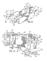
- FIG. 10 is a partial perspective view illustrating a first folding arm operable on the partially formed tray
- FIG. 11 is a top perspective view of the partially formed tray resulting from the folding process of FIG. 10 ;
- FIG. 12 is a partial top perspective view illustrating elements of the apparatus of FIG. 1 securing a fully formed tray therein;
- FIG. 13 is a top perspective view of the partially formed tray resulting from the folding process of FIG. 12 ;
- FIG. 14 is a partial perspective view illustrating a first folding arm operable on the partially formed tray
- FIG. 15 is a partial perspective view illustrating a second folding arm operable on the partially formed tray
- FIG. 16 is a partial end view illustrating an orientation of a compression plate and a first folding arm prior to a folding movement thereby;
- FIG. 17 is a partial perspective view illustrating an orientation of the compression plate, the first folding arm and the second folding arm is a compression orientation for holding corner portions of a fully formed tray;
- FIG. 18 is a top front perspective view of a fully formed tray formed by the apparatus of FIGS. 1-3 ;
- FIG. 19 is a partial enlarged top plan view of one corner portion of the fully formed tray of FIG. 18 ;
- FIG. 20 is a perspective view of a partially formed deep walled container illustrating one container structure to be formed by an alternate embodiment of the invention
- FIG. 21 is a perspective view of a partially formed deep walled container having a lid formed thereon illustrating a container structure to be formed by an alternate embodiment of the invention
- FIG. 22 is a partial perspective view of an alternate embodiment of the invention useful in forming deep walled containers as illustrated in FIG. 20 ;
- FIG. 22A is a partial perspective view of the embodiment illustrated with reference to FIG. 22 without the partially formed container.
- FIGS. 23-25 are partial plan views of the apparatus of FIG. 22 illustrating steps in the forming of the container of FIG. 20 .
- one embodiment of the present invention includes a tray forming apparatus 100 for forming a blank 200 into a fully formed tray 202 .
- the apparatus 100 may further be described to include a platen 102 dimensioned for biasing against the blank 200 using a platen drive 104 operable for moving the platen between a first position 106 proximate and in spaced relation to the blank 200 and a second position 108 , illustrated with reference again to FIG. 2 , through an initial movement and biasing of the platen against the blank for driving the blank downstream from the first position, as illustrated with reference to FIG. 3 .
- a frame 112 carries the drive 104 as well as other forming elements and operable devices of the apparatus 100 later described in this section.
- a forming rail 114 is positioned downstream from the first position 106 for receiving the blank 200 and folding peripheral portions 204 thereof, wherein a proximal portion 116 of the forming rail 114 partially folds the peripheral portions of the blank 200 and a distal portion 118 of the forming rail 114 secures the blank 200 as a partially formed tray 206 , illustrated with reference to FIGS. 4 and 5 , to be further detailed later in this section.
- a first folding arm 120 is pivotally carried by the frame 112 and positioned for biasing against an extended portion 208 of the partially formed tray 206 for a folding thereof.
- a compression plate 122 is pivotally carried by the frame 112 and in a spaced relation to the partially formed tray 206 .
- a fixed plate 124 is carried in a spaced relation to the compression plate 122 to form a passage 126 , to be further detailed later in this section.
- a second folding arm 128 is carried by the frame 112 and positioned for pivoting and biasing against the extended portion 208 of the partially formed tray 206 for folding the extended portion through the passage 126 .
- an in-feed conveyor 130 may be used for conveying the blank 200 to the first position 106 .
- one embodiment may include the conveyor 130 placing the blank 200 at an angle 132 to vertical, and thus in a non-vertical orientation for permitting gravity to slidably hold the blank against a surface of the conveyor 130 while conveying the blank on a rotating belt 134 .
- the apparatus 100 may be operated with the blank 200 entering at a horizontal orientation as well as the angle position herein described.
- the apparatus 100 herein described may include a hot glue applicator 136 for applying an adhesive 138 to the blank 200 , as illustrated with reference to FIG. 7 .
- multiple glue heads 140 may be adjustably carried by the frame 112 for providing a specific spray pattern at a specific glue head temperature and thus a temperature of the glue for allowing the last surface to be glued to have a soft glue sufficient for making appropriate attachment as the first glued surface during the folding and compressing of the blank 200 to form the tray.
- a sensor 146 is positioned for sensing a leading and a trailing edge of the blank 200 for providing a signal to a controller 148 for a timely directed allocation activation signal to allow the adhesive 138 to be applied as desired, such as illustrated with reference again to FIG. 7 .
- the glue heads 140 are directed toward a backstop 150 having a roughened surface 152 for receiving any adhesive 138 that may miss hitting the blank 200 .
- the roughened surface 152 allows any adhesive 138 collected thereon to be easily removed when dry.
- alternate adhesive methods may be employed, now having the benefit of the teachings of the present invention.
- stapling may be employed in conjunction with the various folding and biasing steps in forming the tray.
- an adhesive may be carried by the blank that is responsive to temperature or pressure for activation.
- various shaped blanks having various constructions may be used to form a container having a desirable shape, now given the teachings of the present invention.
- the paperboard blank 200 as illustrated further with reference to FIG. 8 is herein described by way of example only.
- the blank 200 may be described to include a bottom panel 210 with first and second opposing end panels 212 formed at opposing peripheral end portions 214 of the bottom panel via first fold lines 216 .
- First and second opposing side panels 218 are connected to opposing peripheral side portions 220 of the bottom panel 210 via second fold lines 222 .
- An inside corner support member 224 is attached to opposing edges 226 of each of the opposing end panels 212 via a third fold line 228 .
- the inside corner support member 224 includes a fourth fold line 230 for forming a bevel within the tray construction.
- a top wall portion 232 is attached to opposing edges 234 of each opposing side panel 218 via a fifth fold line 236 .
- an outside corner support member 238 is attached to each of the top wall portions 232 via a sixth fold line, wherein the outside corner support member 238 includes a seventh fold line 242 for providing an outside corner support via an end fold portion 244 and a side fold portion 246 .
- the platen 102 may comprise a rectangular peripheral portion 154 dimensioned for folding the rectangular shaped bottom panel 210 of the blank 200 into a rectangular shape.
- the peripheral portion 154 of the platen 102 includes beveled corners 156 , as illustrated with reference again to FIG. 5 , and to FIG. 9 to form the bevel 248 within the inside corner support member 224 .
- the platen 102 is dimensioned and aligned to fit proximate the first and second fold lines 216 , 222 when contacting the bottom panel 210 .
- inside corner support member is herein described by way of example as having a bevel portion, alternatively it may have a single fold to form a squared inside corner. It will be further understood that while the corner construction herein described in relation to the end panel and the side panel, the tray may be constructed in a mirror image or with reference to alternative end and side panels forming the tray.
- a guide plate 158 is carried by the platen 102 for further defining the platen peripheral portion 154 and for providing a compression surface 160 operable with the inside corner support member 224 .
- the compression surface 160 may comprise depressions for reducing a frictional contacting surface thereof.
- the corrugations on the compression side of the guide plates reduce the surface area for providing increased pressure on glue points while at the same time reducing friction between the guide plate surface and the tray inside wall to allow the platen to be more easily removed when being retracted, as earlier described.
- the inside corner support member 224 is folded to about 90° while the side panel 218 is folded upward approximately 30°-45°.
- the end panel 212 is folded up approximately 90° and the side panel 218 is brought up to a 90° fold compressing the side panel 218 , having the adhesive 138 thereon, against the inside corner support member 224 having the guide plate 158 against it.
- the rectangular structure of this sample tray 202 is formed.
- Each guide plate 158 may include adjustment screws for aligning the guide plate 158 and positioning the corrugated surface 160 of the guide plate 158 at a desired attitude when compressing varying styled trays. As a result an adjustable platen 102 is provided.
- the forming rail 114 may include opposing end folding rails 162 positioned for receiving the end panels 212 and dimensioned for upwardly folding the end panels 212 with respect to the bottom panel 210 .
- Opposing edge rails 164 are positioned for inwardly folding outside edge portions of the inside corner support members 224 , herein described by way of example.
- Opposing side folding rails 166 are positioned for receiving the side panels 218 of the blank 200 and for folding the side panels 218 upwardly with respect to the bottom panel 210 while capturing the inside corner support members 224 between the side panels 218 .
- the blank 200 is received at proximal portions 116 of the forming rail 114 , and a distal portion 118 thereof secures the now partially formed tray 206 .
- the forming rail 114 folds the end panels 212 about the first fold lines 216 and the side panels 218 about the second fold lines 222 , with each inside corner support member 224 folded about the third fold line 228 inwardly of the opposing side panels 218 .
- the partially formed tray 206 is configured with the end panels 212 and the side panels 218 positioned generally orthogonal to the bottom panel 210 and each of the inside corner support members 224 folded about the third fold line 228 and in juxtaposition with an adjacent side panel 218 , as illustrated with reference again to FIGS. 5 and 9 .
- Each of the top wall portions 232 and the outside corner support members 238 are generally parallel to respective side panels 218 thereof.
- a locking arm 168 is operable with the folding rail described with reference to FIG. 3 for securing the partially formed tray 206 at the second position 108 , herein shown separately for clarity.
- the platen 102 With the partially formed tray 206 secured in the second position 108 , as illustrated with reference again to FIG. 4 , by way of example, the platen 102 is retracted and the folding of the top wall portions 232 and the outside corner support members 238 commence.
- the first folding arm 120 is operable for folding the top wall portion 232 about the fifth fold line 236 to a position generally parallel to the bottom panel 210 .
- the side fold portion 246 is partially folded about the sixth fold line 240 by passing through the passage 126 formed by the spaced compressed compression plate 122 and the fixed plate 124 .
- the compression plates 122 are moveable for biasing against each of the side fold portions 246 .
- a squared inside corner is illustrated by way of example in FIG. 10 , wherein a squared corner platen 103 would be employed.
- the partial folding of the side fold portion 246 has been shown to improve on the performance and speed in the forming process.
- the fixed plate 124 allows the outside corner support member 238 to stay oriented relative to a plane of the top wall portion 232 resulting in a “squared off” corner construction with vertical walls providing a desired strength needed during stacking of filled trays. By way of example, damage to fruit is avoided especially for the lower trays in the stack.
- the compression plate as herein described is used for both a guide plate to form the passage and a compression plate during movement thereof, alternatively a separate compression plate may be used in conjunction with a separate passage.
- a forming of the outside corner support members 238 commences with the second folding arm 128 rotated against the end fold portions 244 , folding them about the sixth fold lines 240 , and biasing the end fold portions against the end panels 212 .
- an edge 245 of the end fold portion 244 is guided onto the end panel 212 along a surface 125 of the fixed plate 124 for orienting the end fold portion 244 in a preferred orthogonal relation to the bottom panel 210 for enhancing the load bearing strength of the tray 202 , as earlier described.
- a final compression phase includes the compression plate 122 folding of the partially folded side fold portion 246 and compressing thereof as illustrated with reference to FIGS. 16-18 .
- Compression forces act upon each corner of the fully formed tray 202 with the compression plate 122 , the first folding arm 120 , the second folding arm 128 , and the locking arm 168 each providing opposing forces to compress the adhesive 138 against respective tray surfaces, as further illustrated with reference to FIG. 19 including a partial top view of the double glued wall construction.
- the controller 148 earlier described with reference to FIG. 1 is operable with drive devices for each of the platen drive 104 , the compression plate 122 , the first folding arm 120 , the second folding arm 128 , and the locking arm 168 for a timely movement thereof. With such, the fully formed tray 202 may be released from the frame 112 . As illustrated with reference again to FIG.
- a glue-setting phase may be provided as herein described, by way of example, with reference to a magazine styled frame 172 which receives the fully formed tray 202 stops 174 , such as that of the locking arm 168 are released to permit a subsequent tray being formed to push the fully formed and glued tray into the magazine styled frame 172 .
- the magazine styled frame 172 includes framing elements 176 that form an aperture for receiving the tray having an increased outside dimension as a result of the folded corner construction.
- the apparatus 100 herein described by way of example carries three trays within the apparatus with a first tray, a partially formed tray 206 , illustrated with reference again to FIG. 3 in the forming phase followed by the compression phase, a second tray 203 being held in the magazine styled frame section for glue setting, as illustrated with reference again to FIG. 2 , and a third tray, fully formed tray 202 ready to be ejected when another blank is pushed into position for forming into the partially formed tray 206 .
- a conveyor 178 may then be used to receive the fully formed trays 202 for movement to an appropriate loading area, by way of example.
- FIG. 20 there is a need to efficiently form a container 250 that unlike trays 202 typically used to carry produce such as fruit and the like, may have relatively deep side walls 252 , and further may be formed from a lighter weight paperboard than that generally used for trays. While the blank 200 earlier described with reference to FIG. 8 will generally be used, specific panel dimensions will change. By way of the example herein described, the panels forming the side walls 252 of the container 250 will have a longer depth dimension 254 that the depth dimension 256 for the tray 202 illustrated with reference again to FIG. 5 . An improvement to the above described apparatus 100 , herein described, accommodates the requirements for forming the deeper tray or container 250 .
- the container 250 also includes a lid 258 having one portion 258 a of the lid attached to one side panel 218 a and a second portion 258 b of the lid attached to an opposing side panel 218 .
- One improvement to the apparatus 100 includes mechanically powering the initial folding of the blank 200 using the forming rails earlier described but now powering selected forming rails to fold portions of the blank prior to the platen being biased against the blank including a folding up of “end flaps” that provide the inside corner support member 224 and thereafter folding the end panels 212 to assist the platen 102 . As described in greater detail below, these two steps happen prior to and in conjunction with the platen 102 being engaged to move through the folding area. This reduces the platen stroke needed to typically make the initial folds earlier as was earlier described by about 33%.
- FIGS. 2 and 3 illustrating the apparatus 100 for forming the tray 202 having the double glued corner structure above and described with reference to FIG. 19 , by way of example, an improvement to this apparatus 100 is now described, by way of example, as being useful in efficiently forming the deep walled container 250 from the generally flat paperboard blank 200 , as earlier described, but now having alternate dimensions such as the depth dimension 254 described with reference to FIG. 20 .
- the blank 200 includes a plurality of scored fold lines 216 , 222 , 228 , 230 , 236 , 240 , and 242 for defining the bottom panel 210 , opposing end panels 212 , each having opposing edge portions 226 , 224 , and opposing side panels 218 .
- the apparatus 101 is herein described as including the platen 102 movable between the first position 106 and the second position 108 along a path 180 .
- the platen 102 is operable for biasing against the blank 200 positioned within the path 180 for driving the blank downstream from the first position 106 toward the second position 108 .
- the apparatus 101 is modified to include rotatable and powered rails 164 m , 162 m , as illustrated with continued reference to FIG. 22 and to FIG. 23 .
- FIG. 22 By way of illustration with continued reference to FIG.
- First and second opposing edge rail pairs 164 m are mechanically operable for inwardly folding outside edge portions, herein referred to as outside corner supports 224 of the end panels 212 of the blank 201 , as illustrated with reference to FIG. 24 .
- the platen 102 is in the first position 106 .
- the opposing first and second end folding rails 162 m are mechanically operable and positioned for receiving the end panels 212 and folding the end panels upwardly from the bottom panel 210 , as illustrated with reference to FIG. 24 .
- the platen 102 may begin to move from the first position 106 downstream along the path 180 .
- the inside corner support members 224 at the outside edge portions the end panel 212 are now upwardly folded.
- the opposing end folding rails 162 m now fold end panels 212 upwardly, as illustrated with reference to FIG. 25 .
- the opposing first and second side folding rails 166 carried in a fixed position relative to and operable with the platen 102 for receiving the opposing side panels 218 and folding the side panels 218 upwardly from the bottom panel 210 , the opposing side panels 218 capture the inside corner support members 224 and hold them in a folded position until the plate 102 is moved further downstream toward the second position and more fully formed into the container 250 as earlier described for the forming of the tray 202 by the apparatus 100 .
- the bottom panel 210 of the partially formed container has been moved downstream from its initial loading position and is shown to be below a plane 260 of the initial loading position.
- the mechanically operated opposing edge rails 164 m each comprise a shaft 262 rotatably driven by a mechanical linkage 264 for rotating the shaft.
- a folding arm 266 is formed with the shaft 262 so as to perform the folding function above described.
- the opposing end folding rails 162 m herein described may comprise first and second plates 268 , 270 that are moveably adjustable to accommodate varying width end panels 212 .
- a guide element 272 may be attached to the shaft 262 to reduce the amount of whipping and thus reduce the undesired distribution of the adhesive 138 .
- the guide element 272 is thus rotated with the folding arm 266 for appropriate positioning during the folding of the blank 201 .
- the guide element 272 allows adhesive to be desirably applied closer to edges of the blank 201 .
- a method of forming the container 250 from the paperboard blank 201 may be described as positioning the blank 201 at the first forming position 106 wherein the platen 102 is supported in a spaced relation above the blank 201 .
- the platen 102 is dimensioned and aligned to fit proximate the first and second fold lines 216 , 222 when contacting the bottom panel 210 .
- the first and second opposing edge rail pairs 164 m are operated to fold the inside corner support members 224 upwardly about the third fold lines 228 at the end panels 212 .
- the opposing first and second mechanically operable end folding rails 162 m fold the opposing end panels 212 upwardly from the bottom panel 210 along the first folding lines 216 , moving the end panels 212 from a horizontal orientation to a vertical orientation, as illustrated in FIGS. 24 and 25 .
- the platen 102 is moving downstream toward the second position 108 to move the bottom panel 210 to a location below the plane 260 from which it started, as illustrated with reference to FIGS. 22 and 22A .
- a track is provided by the conveyor belts 261 and carried on the plane 260 for moving the blank along the horizontal plane into position for being contacted by the platen 102 .
- the plane 260 is established by a top surface of square tubing, which tubing starts the folding of the opposing side panels 218 prior to being folded by the opposing side folding rails 166 through the movement of the platen 102 .
- the movement of the platen 102 causes the opposing side panels 218 to be upwardly folded about the second folding lines 222 by the first and second side folding rails 166 carried in a fixed position relative to and operable with the platen 102 .
- the biasing of the platen 102 against the bottom panel 210 of the blank 201 for advancing the blank 201 to create a partially formed container 250 downstream from the first forming position 106 folds the side panels 218 upwardly from the bottom panel 210 along the second folding lines 222 sufficient for allowing the opposing side panels 218 to secure the inside corner support members 224 in a folded position biased against inside surfaces of the side panels 218 , as illustrated with reference again to FIG. 22 .
Abstract
Description
Claims (10)
Priority Applications (2)
| Application Number | Priority Date | Filing Date | Title |
|---|---|---|---|
| US12/331,548 US7993255B1 (en) | 2005-08-25 | 2008-12-10 | Apparatus and method for forming a container having an enhanced corner support structure |
| US13/178,720 US8177698B2 (en) | 2002-11-26 | 2011-07-08 | Apparatus and method for forming a container having an enhanced corner support structure |
Applications Claiming Priority (3)
| Application Number | Priority Date | Filing Date | Title |
|---|---|---|---|
| US71127705P | 2005-08-25 | 2005-08-25 | |
| US11/467,312 US7470226B1 (en) | 2002-11-26 | 2006-08-25 | Apparatus and method for forming a container having an enhanced corner support structure |
| US12/331,548 US7993255B1 (en) | 2005-08-25 | 2008-12-10 | Apparatus and method for forming a container having an enhanced corner support structure |
Related Parent Applications (1)
| Application Number | Title | Priority Date | Filing Date |
|---|---|---|---|
| US11/467,312 Continuation US7470226B1 (en) | 2002-11-26 | 2006-08-25 | Apparatus and method for forming a container having an enhanced corner support structure |
Related Child Applications (1)
| Application Number | Title | Priority Date | Filing Date |
|---|---|---|---|
| US13/178,720 Continuation US8177698B2 (en) | 2002-11-26 | 2011-07-08 | Apparatus and method for forming a container having an enhanced corner support structure |
Publications (1)
| Publication Number | Publication Date |
|---|---|
| US7993255B1 true US7993255B1 (en) | 2011-08-09 |
Family
ID=44350723
Family Applications (5)
| Application Number | Title | Priority Date | Filing Date |
|---|---|---|---|
| US11/467,312 Expired - Lifetime US7470226B1 (en) | 2002-11-26 | 2006-08-25 | Apparatus and method for forming a container having an enhanced corner support structure |
| US12/331,548 Expired - Fee Related US7993255B1 (en) | 2002-11-26 | 2008-12-10 | Apparatus and method for forming a container having an enhanced corner support structure |
| US13/178,720 Expired - Lifetime US8177698B2 (en) | 2002-11-26 | 2011-07-08 | Apparatus and method for forming a container having an enhanced corner support structure |
| US13/451,279 Expired - Lifetime US8388507B2 (en) | 2002-11-26 | 2012-04-19 | Tray forming apparatus |
| US13/761,007 Active 2025-02-17 US9174407B2 (en) | 2002-11-26 | 2013-02-06 | Tray forming apparatus |
Family Applications Before (1)
| Application Number | Title | Priority Date | Filing Date |
|---|---|---|---|
| US11/467,312 Expired - Lifetime US7470226B1 (en) | 2002-11-26 | 2006-08-25 | Apparatus and method for forming a container having an enhanced corner support structure |
Family Applications After (3)
| Application Number | Title | Priority Date | Filing Date |
|---|---|---|---|
| US13/178,720 Expired - Lifetime US8177698B2 (en) | 2002-11-26 | 2011-07-08 | Apparatus and method for forming a container having an enhanced corner support structure |
| US13/451,279 Expired - Lifetime US8388507B2 (en) | 2002-11-26 | 2012-04-19 | Tray forming apparatus |
| US13/761,007 Active 2025-02-17 US9174407B2 (en) | 2002-11-26 | 2013-02-06 | Tray forming apparatus |
Country Status (1)
| Country | Link |
|---|---|
| US (5) | US7470226B1 (en) |
Cited By (3)
| Publication number | Priority date | Publication date | Assignee | Title |
|---|---|---|---|---|
| US8388507B2 (en) | 2003-11-25 | 2013-03-05 | Smurfit-Stone Container Corporation | Tray forming apparatus |
| US10118359B2 (en) | 2002-11-26 | 2018-11-06 | Westrock Shared Services, Llc | Tray forming apparatus and method |
| USD980069S1 (en) | 2020-07-14 | 2023-03-07 | Ball Corporation | Metallic dispensing lid |
Families Citing this family (26)
| Publication number | Priority date | Publication date | Assignee | Title |
|---|---|---|---|---|
| US9908304B2 (en) | 2008-05-07 | 2018-03-06 | Westrock Shared Services, Llc | Machine and method for forming reinforced polygonal containers |
| US8827142B2 (en) | 2008-05-07 | 2014-09-09 | Rock-Tenn Shared Services, Llc | Reinforced polygonal containers and blanks of sheet material for making the same |
| US8579778B2 (en) | 2010-05-14 | 2013-11-12 | Rock-Tenn Shared Services, Llc | Machine and method for forming reinforced polygonal containers from blanks |
| US8820618B2 (en) | 2008-05-07 | 2014-09-02 | Rock-Tenn Shared Services, Llc | Reinforced polygonal containers and blanks for making the same |
| US8887982B2 (en) | 2008-05-07 | 2014-11-18 | Rock-Tenn Shared Services, Llc | Hand formed reinforced polygonal containers and blanks for making the same |
| US8105223B2 (en) * | 2008-05-07 | 2012-01-31 | Smurfit-Stone Container Enterprises, Inc. | Machine and method for forming reinforced polygonal containers from blanks |
| US8246527B2 (en) * | 2009-10-21 | 2012-08-21 | J&L Group International, Llc | Systems and methods for folding |
| ES2438115T3 (en) * | 2010-11-05 | 2014-01-15 | Tavil-Indebe, S.A.U. | Multi-format box forming machine |
| AR089636A1 (en) | 2012-01-24 | 2014-09-03 | Tin Inc | CONTAINER TO TRANSPORT ARTICLES |
| AR092668A1 (en) | 2012-09-26 | 2015-04-29 | Tin Inc | CONTAINER FOR PRODUCT TRANSPORTATION |
| US11433634B2 (en) * | 2012-10-19 | 2022-09-06 | Westrock Shared Services, Llc | Container forming apparatus and method |
| US9469078B2 (en) * | 2013-03-15 | 2016-10-18 | Westrock Shared Services, Llc | Methods and apparatus for forming a reinforced container |
| WO2014183067A2 (en) * | 2013-05-10 | 2014-11-13 | Rock-Tenn Shared Services, Llc | Machine and method for forming reinforced polygonal containers |
| CA2912053C (en) * | 2013-05-10 | 2021-10-26 | Westrock Shared Services, Llc | Reinforced polygonal containers and blanks for making the same |
| US9422071B2 (en) * | 2013-07-23 | 2016-08-23 | Ashley John Beck Adams | Automatic, T-fold carton erector and sealer |
| US9290290B2 (en) * | 2014-03-04 | 2016-03-22 | Inteplast Group Corporation | Reusable box blank |
| US9597851B2 (en) * | 2014-08-22 | 2017-03-21 | Southern Champion Tray, L.P. | Push folding of carton blanks |
| US9938031B2 (en) * | 2014-10-27 | 2018-04-10 | Standard Knapp Inc. | Method of processing a plurality of articles through a processing section of a packaging machine and method of reconfiguring a processing section of a packaging machine |
| US9957072B2 (en) | 2014-10-27 | 2018-05-01 | Standard Knapp Inc. | Process section of a packaging machine |
| US9469432B2 (en) | 2014-11-04 | 2016-10-18 | Westrock Shared Services, Llc | Reinforced containers and blanks for making the same |
| USD784806S1 (en) | 2015-01-16 | 2017-04-25 | Georgia-Pacific Corrugated Llc | Box |
| US10350849B2 (en) * | 2015-09-21 | 2019-07-16 | Westrock Shared Services, Llc | Methods and machine for forming a two-piece blank assembly |
| BE1025132B1 (en) * | 2016-04-21 | 2018-11-19 | Didier Groffils | Automatic production line of food containers or not, based on foldable sheets |
| ES2691245B2 (en) * | 2017-05-25 | 2019-05-23 | Telesforo Gonzalez Maqu S L U | Bench reinforcement device corner boxes, mold and machine for the formation of boxes of sheet material from flat plates |
| FR3105082B1 (en) * | 2019-12-18 | 2021-11-26 | Sidel Packing Solutions | Container forming by folding cardboard sheets |
| CN112874005A (en) * | 2021-02-04 | 2021-06-01 | 徐遍红 | Gift packaging box manufacturing and processing method |
Citations (26)
| Publication number | Priority date | Publication date | Assignee | Title |
|---|---|---|---|---|
| US2665836A (en) | 1951-01-10 | 1954-01-12 | Gaylord Container Corp | Produce tray |
| US3978774A (en) | 1974-11-25 | 1976-09-07 | International Paper Company | Tray forming machine |
| US4174658A (en) | 1978-02-06 | 1979-11-20 | R. A. Pearson Company | Tray former |
| US4256025A (en) * | 1979-07-12 | 1981-03-17 | Kliklok Corporation | Apparatus for forming a hinged carton |
| US4289491A (en) * | 1979-06-25 | 1981-09-15 | Kliklok Corporation | Apparatus for adhesively bonding a carton |
| US4418863A (en) | 1982-09-02 | 1983-12-06 | Georgia-Pacific Corporation | Produce tray with reinforced corner construction |
| US4460349A (en) | 1982-04-26 | 1984-07-17 | Manville Service Corporation | Paperboard tray forming machine |
| US4500306A (en) * | 1982-06-29 | 1985-02-19 | International Paper Company | Method and apparatus for erecting a carton with integral interior partitions |
| US4578054A (en) | 1983-11-17 | 1986-03-25 | Herrin Robert M | Carton erection and sealing apparatus |
| US4651501A (en) | 1985-07-08 | 1987-03-24 | Mitsubishi Jukogyo Kabushiki Kaisha | Wrapping machine for use in a packaging system |
| US4835944A (en) | 1987-11-02 | 1989-06-06 | Herrin Robert M | Carton nesting apparatus and method |
| US4936815A (en) | 1988-04-18 | 1990-06-26 | Liberty Diversified Industries | Tray forming machine |
| US4988331A (en) | 1987-03-06 | 1991-01-29 | Vega Automation | Programmable dynamically adjustable plunger and tray former apparatus and method of adjusting |
| US5024641A (en) | 1987-03-06 | 1991-06-18 | Vega Automation | Programmable dynamically adjustable plunger and tray former apparatus |
| US5131208A (en) | 1991-01-31 | 1992-07-21 | Radco Industries, Inc. | Method and apparatus for forming cartons |
| US5452844A (en) | 1991-05-30 | 1995-09-26 | Packart Holding | Stand-up type sachet intended to contain a liquid, pasty or pulverulent product |
| US5782732A (en) | 1996-11-29 | 1998-07-21 | Herrin; Robert M. | Tray forming apparatus and method of forming same |
| US5797716A (en) | 1996-08-30 | 1998-08-25 | Herrin; Robert M. | Container contents unloading apparatus for unloading contents of a container and method of unloading same |
| US5807223A (en) | 1995-06-07 | 1998-09-15 | Sanger Works Factory, Inc. | Container forming method and apparatus |
| US5853120A (en) | 1996-07-31 | 1998-12-29 | Stone Container Corporation | Tray apparatus with reinforced corner structure |
| US5916078A (en) | 1996-04-24 | 1999-06-29 | Herrin; Robert M. | Container stuffing or nesting apparatus |
| US5971906A (en) | 1996-11-29 | 1999-10-26 | Tharpe, Jr.; Johnny M. | Tray forming apparatus and method |
| US6226965B1 (en) | 1999-12-08 | 2001-05-08 | Belcor Industries Inc | Inline case sealing system |
| US6306070B1 (en) | 1999-12-29 | 2001-10-23 | Robert M. Herrin | Apparatus for erecting and sealing flat containers and associated methods |
| US6422802B1 (en) | 2000-07-19 | 2002-07-23 | Robert M. Herrin | Produce unloading apparatus and associated methods for achieving smooth discharge and return |
| US6622461B2 (en) | 2001-02-05 | 2003-09-23 | Baumer S.R.L. | Method and system for closure of the flaps of the end sides of a package in the form of a sleeve |
Family Cites Families (6)
| Publication number | Priority date | Publication date | Assignee | Title |
|---|---|---|---|---|
| US4283190A (en) * | 1977-04-12 | 1981-08-11 | Williams Donald F | Method for forming paper boxes and the like |
| US4345905A (en) * | 1977-10-31 | 1982-08-24 | Moen Lenard E | Making of containers with tri-laminated end walls |
| US4650501A (en) | 1984-10-05 | 1987-03-17 | Union Carbide Corporation | Pressure swing adsorption process |
| US5656006A (en) * | 1995-01-13 | 1997-08-12 | Swf Machinery, Inc. | Method and apparatus for forming a work object |
| US7470226B1 (en) | 2002-11-26 | 2008-12-30 | R & L Manufacturing | Apparatus and method for forming a container having an enhanced corner support structure |
| US8177699B1 (en) | 2002-11-26 | 2012-05-15 | Smurfit-Stone Container Corporation | Tray forming apparatus |
-
2006
- 2006-08-25 US US11/467,312 patent/US7470226B1/en not_active Expired - Lifetime
-
2008
- 2008-12-10 US US12/331,548 patent/US7993255B1/en not_active Expired - Fee Related
-
2011
- 2011-07-08 US US13/178,720 patent/US8177698B2/en not_active Expired - Lifetime
-
2012
- 2012-04-19 US US13/451,279 patent/US8388507B2/en not_active Expired - Lifetime
-
2013
- 2013-02-06 US US13/761,007 patent/US9174407B2/en active Active
Patent Citations (27)
| Publication number | Priority date | Publication date | Assignee | Title |
|---|---|---|---|---|
| US2665836A (en) | 1951-01-10 | 1954-01-12 | Gaylord Container Corp | Produce tray |
| US3978774A (en) | 1974-11-25 | 1976-09-07 | International Paper Company | Tray forming machine |
| US4174658A (en) | 1978-02-06 | 1979-11-20 | R. A. Pearson Company | Tray former |
| US4289491A (en) * | 1979-06-25 | 1981-09-15 | Kliklok Corporation | Apparatus for adhesively bonding a carton |
| US4256025A (en) * | 1979-07-12 | 1981-03-17 | Kliklok Corporation | Apparatus for forming a hinged carton |
| US4460349A (en) | 1982-04-26 | 1984-07-17 | Manville Service Corporation | Paperboard tray forming machine |
| US4500306A (en) * | 1982-06-29 | 1985-02-19 | International Paper Company | Method and apparatus for erecting a carton with integral interior partitions |
| US4418863A (en) | 1982-09-02 | 1983-12-06 | Georgia-Pacific Corporation | Produce tray with reinforced corner construction |
| US4578054A (en) | 1983-11-17 | 1986-03-25 | Herrin Robert M | Carton erection and sealing apparatus |
| US4651501A (en) | 1985-07-08 | 1987-03-24 | Mitsubishi Jukogyo Kabushiki Kaisha | Wrapping machine for use in a packaging system |
| US4988331A (en) | 1987-03-06 | 1991-01-29 | Vega Automation | Programmable dynamically adjustable plunger and tray former apparatus and method of adjusting |
| US5024641A (en) | 1987-03-06 | 1991-06-18 | Vega Automation | Programmable dynamically adjustable plunger and tray former apparatus |
| US4835944A (en) | 1987-11-02 | 1989-06-06 | Herrin Robert M | Carton nesting apparatus and method |
| US4936815A (en) | 1988-04-18 | 1990-06-26 | Liberty Diversified Industries | Tray forming machine |
| US5131208A (en) | 1991-01-31 | 1992-07-21 | Radco Industries, Inc. | Method and apparatus for forming cartons |
| US5452844A (en) | 1991-05-30 | 1995-09-26 | Packart Holding | Stand-up type sachet intended to contain a liquid, pasty or pulverulent product |
| US5807223A (en) | 1995-06-07 | 1998-09-15 | Sanger Works Factory, Inc. | Container forming method and apparatus |
| US5916078A (en) | 1996-04-24 | 1999-06-29 | Herrin; Robert M. | Container stuffing or nesting apparatus |
| US5853120A (en) | 1996-07-31 | 1998-12-29 | Stone Container Corporation | Tray apparatus with reinforced corner structure |
| US5979746A (en) | 1996-07-31 | 1999-11-09 | Stone Container Corporation | Tray apparatus with reinforced corner structure |
| US5797716A (en) | 1996-08-30 | 1998-08-25 | Herrin; Robert M. | Container contents unloading apparatus for unloading contents of a container and method of unloading same |
| US5782732A (en) | 1996-11-29 | 1998-07-21 | Herrin; Robert M. | Tray forming apparatus and method of forming same |
| US5971906A (en) | 1996-11-29 | 1999-10-26 | Tharpe, Jr.; Johnny M. | Tray forming apparatus and method |
| US6226965B1 (en) | 1999-12-08 | 2001-05-08 | Belcor Industries Inc | Inline case sealing system |
| US6306070B1 (en) | 1999-12-29 | 2001-10-23 | Robert M. Herrin | Apparatus for erecting and sealing flat containers and associated methods |
| US6422802B1 (en) | 2000-07-19 | 2002-07-23 | Robert M. Herrin | Produce unloading apparatus and associated methods for achieving smooth discharge and return |
| US6622461B2 (en) | 2001-02-05 | 2003-09-23 | Baumer S.R.L. | Method and system for closure of the flaps of the end sides of a package in the form of a sleeve |
Cited By (4)
| Publication number | Priority date | Publication date | Assignee | Title |
|---|---|---|---|---|
| US9174407B2 (en) | 2002-11-26 | 2015-11-03 | Westrock Shared Services, Llc | Tray forming apparatus |
| US10118359B2 (en) | 2002-11-26 | 2018-11-06 | Westrock Shared Services, Llc | Tray forming apparatus and method |
| US8388507B2 (en) | 2003-11-25 | 2013-03-05 | Smurfit-Stone Container Corporation | Tray forming apparatus |
| USD980069S1 (en) | 2020-07-14 | 2023-03-07 | Ball Corporation | Metallic dispensing lid |
Also Published As
| Publication number | Publication date |
|---|---|
| US9174407B2 (en) | 2015-11-03 |
| US8388507B2 (en) | 2013-03-05 |
| US20130150223A1 (en) | 2013-06-13 |
| US20110269609A1 (en) | 2011-11-03 |
| US8177698B2 (en) | 2012-05-15 |
| US7470226B1 (en) | 2008-12-30 |
| US20120202666A1 (en) | 2012-08-09 |
Similar Documents
| Publication | Publication Date | Title |
|---|---|---|
| US7993255B1 (en) | Apparatus and method for forming a container having an enhanced corner support structure | |
| US10118359B2 (en) | Tray forming apparatus and method | |
| US4581005A (en) | Manufacture of boxes with integrally reinforced walls | |
| US8671654B2 (en) | Method and system for forming containers with corrugated material | |
| US20050124478A1 (en) | Side wall flap folding mechanism for carton forming machine | |
| EP2367680B1 (en) | Manual feed box erector and sealer | |
| JPS597577B2 (en) | Box material folding device | |
| US7329218B2 (en) | Feed apparatus and method for feeding blanks into container forming machines | |
| US4661091A (en) | Machine for manufacture of boxes with integrally reinforced walls | |
| US20060162295A1 (en) | Wrap around carton packaging machine | |
| US4006670A (en) | Method and apparatus for forming a collapsed box | |
| US3673763A (en) | Carton erecting and packaging machine | |
| US5853360A (en) | Method and apparatus for producing a gusseted container | |
| US4892513A (en) | Carton erector apparatus | |
| EP0685328B1 (en) | Boxed pocket folding machine | |
| CN116513868B (en) | Corrugated paper collecting device, corrugated paper printing and packaging machine and paper collecting method | |
| US4066008A (en) | Carton forming machine | |
| US4657527A (en) | Flap folding mechanism for manufacture of boxes with integrally reinforced walls | |
| CN214083128U (en) | Paste punch-out equipment | |
| US4441377A (en) | Linkage for actuating a carton erecting apparatus | |
| US5085623A (en) | Bar scoring apparatus | |
| CN213201369U (en) | Unloader and have this unloader's full-automatic nail all-in-one that glues | |
| CN113246531B (en) | Carton sealing device for corrugated carton production | |
| US3626820A (en) | Apparatus for producing cartons | |
| US20050079966A1 (en) | Positioning apparatus for container forming machine |
Legal Events
| Date | Code | Title | Description |
|---|---|---|---|
| AS | Assignment |
Owner name: SMURFIT-STONE CONTAINER CORPORATION, ILLINOIS Free format text: ASSIGNMENT OF ASSIGNORS INTEREST;ASSIGNOR:R&L MANUFACTURING, INC.;REEL/FRAME:025146/0218 Effective date: 20100914 |
|
| AS | Assignment |
Owner name: R&L MANUFACTURING, INC., FLORIDA Free format text: NUNC PRO TUNC ASSIGNMENT;ASSIGNOR:HERRIN, ROBERT;REEL/FRAME:025238/0571 Effective date: 20101027 |
|
| STCF | Information on status: patent grant |
Free format text: PATENTED CASE |
|
| AS | Assignment |
Owner name: ROCKTENN CP, LLC, GEORGIA Free format text: MERGER;ASSIGNOR:SMURFIT-STONE CONTAINER CORPORATION;REEL/FRAME:031122/0131 Effective date: 20110527 |
|
| AS | Assignment |
Owner name: ROCK-TENN SHARED SERVICES, LLC, GEORGIA Free format text: ASSIGNMENT OF ASSIGNORS INTEREST;ASSIGNOR:ROCKTENN CP, LLC;REEL/FRAME:031247/0991 Effective date: 20130920 |
|
| FPAY | Fee payment |
Year of fee payment: 4 |
|
| AS | Assignment |
Owner name: WESTROCK SHARED SERVICES, LLC, GEORGIA Free format text: CHANGE OF NAME;ASSIGNOR:ROCK-TENN SHARED SERVICES, LLC;REEL/FRAME:037057/0404 Effective date: 20150901 |
|
| MAFP | Maintenance fee payment |
Free format text: PAYMENT OF MAINTENANCE FEE, 8TH YEAR, LARGE ENTITY (ORIGINAL EVENT CODE: M1552); ENTITY STATUS OF PATENT OWNER: LARGE ENTITY Year of fee payment: 8 |
|
| FEPP | Fee payment procedure |
Free format text: MAINTENANCE FEE REMINDER MAILED (ORIGINAL EVENT CODE: REM.); ENTITY STATUS OF PATENT OWNER: LARGE ENTITY |
|
| LAPS | Lapse for failure to pay maintenance fees |
Free format text: PATENT EXPIRED FOR FAILURE TO PAY MAINTENANCE FEES (ORIGINAL EVENT CODE: EXP.); ENTITY STATUS OF PATENT OWNER: LARGE ENTITY |
|
| STCH | Information on status: patent discontinuation |
Free format text: PATENT EXPIRED DUE TO NONPAYMENT OF MAINTENANCE FEES UNDER 37 CFR 1.362 |
|
| FP | Lapsed due to failure to pay maintenance fee |
Effective date: 20230809 |