US7986195B2 - Digital FM modulator - Google Patents
Digital FM modulator Download PDFInfo
- Publication number
- US7986195B2 US7986195B2 US12/036,377 US3637708A US7986195B2 US 7986195 B2 US7986195 B2 US 7986195B2 US 3637708 A US3637708 A US 3637708A US 7986195 B2 US7986195 B2 US 7986195B2
- Authority
- US
- United States
- Prior art keywords
- function
- signal
- oscillator
- cosine
- sine
- Prior art date
- Legal status (The legal status is an assumption and is not a legal conclusion. Google has not performed a legal analysis and makes no representation as to the accuracy of the status listed.)
- Expired - Fee Related, expires
Links
Images


Classifications
-
- H—ELECTRICITY
- H03—ELECTRONIC CIRCUITRY
- H03C—MODULATION
- H03C3/00—Angle modulation
- H03C3/02—Details
Definitions
- the invention relates generally to a digital FM modulator. More specifically, the invention relates to FM modulation with signal decomposition.
- Digital FM modulators may be used for transmitting signals over a frequency modulated (FM) wave.
- FM modulation the frequency of a carrier wave varies in a continuous manner based on an analog message signal.
- changes in the message signal include integration of the message signal followed by phase shifting of the message signal.
- phase shifting of the signal in a digital FM modulator values are chosen from a list of entries in a lookup table that conveys a different possible symbol or piece of information.
- a frequency of a carrier signal is varied by adding a time varying component such that the frequency may be the unmodulated carrier frequency plus a deviation from the carrier frequency with respect to the input message signal.
- phase shifting of the integrated message signal may be problematic in digital signal processing hardware.
- phase shifting of the integrated message signal may be time and power consuming. For example, an input signal is received and processed and the processed input signal is then matched on a table of entries in a lookup table for phase shifting. A corresponding lookup table entry is selected to obtain the phase-shifted FM modulated signal.
- FIG. 1 illustrates a typical modulator.
- a message signal may be integrated by an integrator 101 .
- the output of the integrator 101 provides an integrated message signal which is used to phase shift the carrier in the phase shifter 102 and modulator 103 to result in the output modulated signal.
- phase shifting of the message signal may be both time consuming and costly as a lookup table is used to obtain the FM modulated signal. Therefore, a need exists for FM modulation in an efficient manner such that a message signal may be computed in digital signal processing hardware in a power and time-saving manner.
- a method for modulating a carrier signal in FM modulation.
- a message signal may be integrated and decomposed into a complex signal.
- the complex signal may be modulated, for example, with at least two AM modulators operating in quadrature.
- a digital FM modulator including an integrator for integrating a message signal and a decomposing unit for decomposing the integrated message signal into a complex signal.
- the complex signal may comprise at least two complex components (e.g., a sine and a cosine component).
- the at least two complex components may interfere to produce a modulated signal.
- FIG. 1 illustrates a typical digital FM modulator.
- FIG. 2 illustrates an example of a method for determining a modulated carrier signal in a digital FM modulator in accordance with an aspect of one embodiment.
- FIG. 3 is a partial block diagram illustrating an example of a digital FM modulator in accordance with an aspect of one embodiment.
- FM modulation a bit stream of data is modulated for transmission based on the frequency of a carrier wave. Modulation of the data facilitates transfer of the information over a transmission medium.
- frequency modulation the frequency of a carrier wave is adjusted based on the transmitted signal. When the signal is high, the frequency of the carrier wave is increased. Conversely, when the signal is low, the frequency of the carrier wave may be decreased.
- ⁇ (t) represents the phase and may be written as:
- ⁇ ⁇ ( t ) K ⁇ ⁇ - ⁇ t ⁇ f ⁇ ( t ) ⁇ d t
- f(t) represents the frequency of the carrier response to a message signal.
- the range of f(t) may vary in the interval [ ⁇ A, A], where A represents the amplitude of the message signal.
- the range of the phase ⁇ (t) may range in the interval [ ⁇ , ⁇ ], for example.
- f(t) may vary by adding a time varying component to the carrier frequency.
- K is a scaling factor and m(t) is the message signal.
- K*m(t) represents the deviation from the carrier frequency based on the message signal in this example.
- an FM modulator integrates the message signal prior to modulating the signal such that the integrated signal is used in place of the phase.
- the carrier may be expressed as follows:
- the message signal is first integrated and then used in place of the phase for phase shifting and modulating.
- the integrated message signal is decomposed to provide a complex signal for modulation.
- phase shifting of the signal is not needed.
- lookup tables are also not necessary.
- the carrier signal may be represented as a cosine signal.
- the carrier signal may be FM modulated with a phase shift of ⁇ (t) as a function of the message signal as follows.
- C m ( t ) A cos( ⁇ t + ⁇ ( t ))
- the frequency of the input message signal may be related to the phase ⁇ (t) as follows:
- ⁇ ⁇ ( t ) K ⁇ ⁇ - ⁇ t ⁇ f ⁇ ( t ) ⁇ d t
- the function ⁇ (t) may vary within a range given by the amplitude of the message signal. For example, if the amplitude of the message signal is [ ⁇ A, A], then the range of f(t) may range in the interval [ ⁇ A, A]. In this example, the range of ⁇ (t) may be in the range of [ ⁇ , ⁇ ].
- the message signal is integrated, then decomposed into a complex signal comprising cosine and sine components. Modulation of the signal is accomplished on the complex signal and phase shifting is not necessary.
- functions representing the modulated carrier signal may be implemented in a digital oscillator.
- components of the modulation of the signal may be provided by a function generator.
- cos ⁇ (n+1) may be expressed by a cosine function generator and sin ⁇ (n+1) may be implemented by a sine function generator.
- FIG. 2 illustrates an example of a method for digital FM modulation.
- a modulating carrier signal is received (STEP 120 ).
- the modulating carrier signal may be processed, for example, by in integrator, and decomposed into a complex signal.
- the integrated signal may be decomposed into cosine and sine components to produce the least one complex signal (STEP 121 ).
- the complex signal may be modulated (STEP 122 ) without the need for phase shifting.
- the complex components of the signal such as a cosine component and a sine component, may interfere with each other to produce an FM modulated signal.
- no lookup table is necessary in modulation.
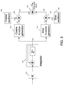
- FIG. 3 is a partial block diagram illustrating an example of an FM modulator.
- the FM modulator may contain a gain adjustment component 201 in which the gain of a message signal may be adjusted with a gain of K.
- the message signal may be further processed in the integrator 202 .
- the integrator 202 may integrate the message signal which may provide for decomposition of the messaging signal into a complex signal.
- the output 220 of the integrator 202 may be an integrated function ⁇ (t) determined as a function over time of the amplitude of the message signal.
- ⁇ (t) may be represented as a function of the signal sample n as ⁇ (n) or ⁇ (n+1).
- the FM modulator may include function generators.
- the FM modulator contains a cosine function generator 203 and a sine function generator 204 .
- the cosine function generator 203 and the sine function generator 204 are merely examples and that any number of function generators of any type may be included in the FM modulator.
- the function generators may form a decomposing unit with the integrator 202 .
- the cosine function generator 203 and the integrator 202 may form a decomposing unit for decomposing a message signal into a cosine component of a complex signal.
- the sine function generator 204 and the integrator 202 may form a decomposing unit for decomposing a message signal into a sine component of a complex signal.
- the cosine function generator 203 and the sine function generator 204 may decompose the integrated message signal into a complex signal that may include a cosine component from the cosine function generator 203 and a sine component from the sine function generator 204 .
- the output of the cosine function generator 203 and the output of the sine function generator 204 from the integrator 202 may provide two complex components of a complex signal based on the original signal.
- the output of the integrator 202 may be a function of the modulated signal in terms of the number of samples processed n as ⁇ (n+1) and may be further processed by the cosine function generator 203 .
- the output 221 of the cosine function generator 203 may be cos ⁇ (n+1).
- the output 220 of integrator 202 may be processed by the sine function generator 204 with an output 222 of sin ⁇ (n+1).
- the FM modulator illustrated in the example of FIG. 3 may further include a cosine oscillator 208 and a sine oscillator 209 .
- the cosine oscillator 203 and the sine oscillator 209 may be AM modulators that may oscillate in quadrature.
- two AM modulators are illustrated, however, any number of AM modulators may be used.
- a complex modulator may be used to remove a side band of the modulating or message signal in which additional AM modulators may be used.
- the cosine oscillator 208 provides a cosine component of the modulated signal as a function of the number of samples and/or the ratio between the oscillator frequency and the sample rate of the digital modulator. For example, if the ratio between the oscillator frequency and the sample rate of the digital modulator is given as ⁇ , the sample given as n, the next sample given as (n+1) and the previous sample as (n ⁇ 1), then the output 223 of the cosine oscillator 208 may be, for example, cos [(n+1) ⁇ ] which may be further provided by the cosine oscillator 208 as [2 cos ⁇ cos(n ⁇ ) ⁇ cos [(n ⁇ 1) ⁇ ]].
- the sine oscillator 209 may provide a sine component of the modulated signal as a function of the number of samples and/or the ratio between the oscillator frequency and the sample rate of the digital modulator.
- the output 224 of the sine oscillator 209 may be sin [(n+1) ⁇ ] which may be further provided by the sine oscillator 209 as [2 cos ⁇ sin(n ⁇ ) ⁇ sin [(n ⁇ 1) ⁇ ]].
- the output 221 of the cosine function generator 203 and the output 223 of the cosine oscillator 208 may be further processed by a multiplier 205 .
- the output 225 of the multiplier 205 may be the product of the output of the cosine function generator 203 (in this example, equal to cos ⁇ (n+1)) and the output of the cosine oscillator 208 (in this example, equal to cos [(n+1) ⁇ ]).
- the output of the multiplier 205 ( 225 ) may be ⁇ cos ⁇ (n+1)cos [(n+1) ⁇ ] ⁇ .
- the output 222 of the sine function generator 204 and the output 224 of the sine oscillator 209 may be processed by a multiplier 206 such that the output 226 of the multiplier 206 may be the product of the output 222 of the sine function generator 204 (in this example, equal to sin ⁇ (n+1)) and the output 224 of the sine oscillator 209 (in this example, equal to sin [(n+1) ⁇ ].
- the output 226 of the multiplier 206 may be ⁇ sin ⁇ (n+1)sin [(n+1) ⁇ ] ⁇ .
- the FM modulator in this example may further include a subtractor 207 in which the output of multiplier 205 ( 225 ) and the output of multiplier 206 ( 226 ) may be added or subtracted to form the modulated signal 227 .
- the modulated signal 227 may be provided by the FM modulator without phase shifting of the carrier. Also, lookup tables are not necessary in modulating of the signal.
- the integrator 202 and cosine function generator 203 may provide an output 221 of cos ⁇ (n+1) and the integrator 202 and the sine function generator 204 may provide an output 222 of sin ⁇ (n+1).
- the multiplier 205 may multiply the output of the cosine oscillator 223 with the output of the integrator 202 and the cosine function generator 203 .
- the output of the multiplier 205 ( 225 ) may be expressed as follows: cos [(n+1) ⁇ ] cos ⁇ (n+1)
- the multiplier 206 may multiply the output of the sine oscillator 224 with the output of the integrator 202 and the sine function generator 204 ( 222 ).
- the output of the multiplier 206 may be given as follows: sin [(n+1) ⁇ ] sin ⁇ (n+1)
- the output of the multiplier 206 ( 226 ) may be subtracted from the output of the multiplier 205 ( 225 ) by an adder/subtractor 207 .
- the digital FM modulator may be implemented in hardware blocks with each component being a hardware component.
- the modulator may be implemented in a DSP processor such that computations performed by each component of the modulator may be performed in software.
- the modulator may be implemented as a component of a processor or other component or may be implemented as a separate, dedicated hardware device or software module.
- the modulator may further be implemented as a dedicated hardware device and in a DSP processor or a software module.
- a portion of the modulator may be provided in a dedicated hardware device and another portion may be provided in a DSP processor.
- a FM modulator is provided in which look up tables are not used. Because lookup tables are not used, different carrier frequencies may be conveniently used with the same hardware components.
Landscapes
- Transmitters (AREA)
- Digital Transmission Methods That Use Modulated Carrier Waves (AREA)
Abstract
Description
C m(t)=A cos(ωt+Φ(t))
f(t)=f c +K*m(t)
C(t)=A cos(ωt)
C m(t)=A cos(ωt+Φ(t))
C m(n)=A cos [nθ+Φ(n)]
C m(n+1)=A cos [(n+1)θ+Φ(n+1)]
C m(n+1)=A { cos [(n+1)θ] cos Φ(n+1)−sin [(n+1)θ] sin Φ(n+1)}
cos [(n+1)θ]=2 cos θ cos(nθ)−cos [(n−1)θ]
sin [(n+1)θ]=2 cos θ sin(nθ)−sin [(n−1)θ]
cos [(n+1)θ]=2 cos θ cos(n θ)−cos [(n−1)θ]
sin [(n+1)θ]=2 cos θ sin(n θ)−sin [(n−1)θ]
cos [(n+1)θ] cos Φ(n+1)
sin [(n+1)θ] sin Φ(n+1)
C m(n+1)=A{ cos [(n+1)θ] cos Φ(n+1)−sin [(n+1)θ] sin Φ(n+1)}
Claims (21)
Priority Applications (1)
| Application Number | Priority Date | Filing Date | Title |
|---|---|---|---|
| US12/036,377 US7986195B2 (en) | 2007-02-26 | 2008-02-25 | Digital FM modulator |
Applications Claiming Priority (2)
| Application Number | Priority Date | Filing Date | Title |
|---|---|---|---|
| US90360907P | 2007-02-26 | 2007-02-26 | |
| US12/036,377 US7986195B2 (en) | 2007-02-26 | 2008-02-25 | Digital FM modulator |
Publications (2)
| Publication Number | Publication Date |
|---|---|
| US20080204159A1 US20080204159A1 (en) | 2008-08-28 |
| US7986195B2 true US7986195B2 (en) | 2011-07-26 |
Family
ID=39715214
Family Applications (1)
| Application Number | Title | Priority Date | Filing Date |
|---|---|---|---|
| US12/036,377 Expired - Fee Related US7986195B2 (en) | 2007-02-26 | 2008-02-25 | Digital FM modulator |
Country Status (1)
| Country | Link |
|---|---|
| US (1) | US7986195B2 (en) |
Cited By (3)
| Publication number | Priority date | Publication date | Assignee | Title |
|---|---|---|---|---|
| US20110033003A1 (en) * | 2009-08-05 | 2011-02-10 | The Aerospace Corporation | Generalized frequency modulation |
| US8264388B1 (en) * | 2010-07-21 | 2012-09-11 | Applied Micro Circuits Corporation | Frequency integrator with digital phase error message for phase-locked loop applications |
| CN102709711A (en) * | 2012-05-22 | 2012-10-03 | 北京东方联星科技有限公司 | Improved beam pointing phase adjusting method and beam pointing module |
Citations (3)
| Publication number | Priority date | Publication date | Assignee | Title |
|---|---|---|---|---|
| US5091705A (en) * | 1989-04-07 | 1992-02-25 | Sharp Kabushiki Kaisha | Fm modulator |
| US5121412A (en) * | 1989-01-03 | 1992-06-09 | Motorola, Inc. | All-digital quadrature modulator |
| US5905413A (en) * | 1996-11-22 | 1999-05-18 | Oki Electric Industry Co., Ltd. | Angular modulator with a phase variation divided and integrated |
-
2008
- 2008-02-25 US US12/036,377 patent/US7986195B2/en not_active Expired - Fee Related
Patent Citations (3)
| Publication number | Priority date | Publication date | Assignee | Title |
|---|---|---|---|---|
| US5121412A (en) * | 1989-01-03 | 1992-06-09 | Motorola, Inc. | All-digital quadrature modulator |
| US5091705A (en) * | 1989-04-07 | 1992-02-25 | Sharp Kabushiki Kaisha | Fm modulator |
| US5905413A (en) * | 1996-11-22 | 1999-05-18 | Oki Electric Industry Co., Ltd. | Angular modulator with a phase variation divided and integrated |
Cited By (5)
| Publication number | Priority date | Publication date | Assignee | Title |
|---|---|---|---|---|
| US20110033003A1 (en) * | 2009-08-05 | 2011-02-10 | The Aerospace Corporation | Generalized frequency modulation |
| US8638890B2 (en) | 2009-08-05 | 2014-01-28 | The Aerospace Corporation | Generalized frequency modulation |
| US8971444B2 (en) * | 2009-08-05 | 2015-03-03 | Rajendra Kumar | Generalized frequency modulation |
| US8264388B1 (en) * | 2010-07-21 | 2012-09-11 | Applied Micro Circuits Corporation | Frequency integrator with digital phase error message for phase-locked loop applications |
| CN102709711A (en) * | 2012-05-22 | 2012-10-03 | 北京东方联星科技有限公司 | Improved beam pointing phase adjusting method and beam pointing module |
Also Published As
| Publication number | Publication date |
|---|---|
| US20080204159A1 (en) | 2008-08-28 |
Similar Documents
| Publication | Publication Date | Title |
|---|---|---|
| JPH0681169B2 (en) | Quadrature modulation method and device | |
| JP4316965B2 (en) | Method and apparatus for modulating a carrier having amplitude and phase error compensation | |
| US6308057B1 (en) | Radio receiver having compensation for direct current offset | |
| US20090213960A1 (en) | Transmitter | |
| US7711336B2 (en) | Single sideband mixer and method of extracting single sideband signal | |
| US7986195B2 (en) | Digital FM modulator | |
| US7881397B2 (en) | Wireless communication system | |
| EP0403085B1 (en) | Responsive simultaneous frequency agile radar | |
| US10680863B2 (en) | Modulation apparatus | |
| US20010041542A1 (en) | Modulated local oscillator | |
| US4475216A (en) | FSK Data transceiver | |
| US6826389B2 (en) | Transmitter and method of generating a transmission signal | |
| JP2843699B2 (en) | Digitized quadrature modulator | |
| CN108604906B (en) | Circuit arrangement and method for generating high frequency analog transmit signals | |
| US7164327B2 (en) | Compensation of the IQ phase asymmetry in quadrature modulation and demodulation methods | |
| US6901114B2 (en) | Transmitter and method of generating a transmission signal | |
| JPH06120990A (en) | Orthogonal modulation circuit | |
| US7876169B2 (en) | Modulating circuit | |
| JPH08265381A (en) | Quadrature modulator | |
| KR100246539B1 (en) | A direct conversion rz ssb transmitter | |
| JP3361731B2 (en) | Quadrature modulator | |
| JPH05207080A (en) | Modulator | |
| JP2002152293A (en) | Modulation circuit | |
| JPH03171953A (en) | Linear modulator | |
| JPH09181781A (en) | transceiver |
Legal Events
| Date | Code | Title | Description |
|---|---|---|---|
| AS | Assignment |
Owner name: MENTOR GRAPHICS CORPORATION, OREGON Free format text: ASSIGNMENT OF ASSIGNORS INTEREST;ASSIGNOR:RAMIREZ, SERGIO R.;REEL/FRAME:020841/0715 Effective date: 20080422 Owner name: MENTOR GRAPHICS CORPORATION,OREGON Free format text: ASSIGNMENT OF ASSIGNORS INTEREST;ASSIGNOR:RAMIREZ, SERGIO R.;REEL/FRAME:020841/0715 Effective date: 20080422 |
|
| STCF | Information on status: patent grant |
Free format text: PATENTED CASE |
|
| FEPP | Fee payment procedure |
Free format text: PAYOR NUMBER ASSIGNED (ORIGINAL EVENT CODE: ASPN); ENTITY STATUS OF PATENT OWNER: LARGE ENTITY |
|
| FPAY | Fee payment |
Year of fee payment: 4 |
|
| FEPP | Fee payment procedure |
Free format text: MAINTENANCE FEE REMINDER MAILED (ORIGINAL EVENT CODE: REM.); ENTITY STATUS OF PATENT OWNER: LARGE ENTITY |
|
| LAPS | Lapse for failure to pay maintenance fees |
Free format text: PATENT EXPIRED FOR FAILURE TO PAY MAINTENANCE FEES (ORIGINAL EVENT CODE: EXP.); ENTITY STATUS OF PATENT OWNER: LARGE ENTITY |
|
| STCH | Information on status: patent discontinuation |
Free format text: PATENT EXPIRED DUE TO NONPAYMENT OF MAINTENANCE FEES UNDER 37 CFR 1.362 |
|
| FP | Lapsed due to failure to pay maintenance fee |
Effective date: 20190726 |