US7958619B1 - Disk chuck with radial force limiter - Google Patents
Disk chuck with radial force limiter Download PDFInfo
- Publication number
- US7958619B1 US7958619B1 US11/686,569 US68656907A US7958619B1 US 7958619 B1 US7958619 B1 US 7958619B1 US 68656907 A US68656907 A US 68656907A US 7958619 B1 US7958619 B1 US 7958619B1
- Authority
- US
- United States
- Prior art keywords
- chuck
- collet
- fingers
- disk
- base
- Prior art date
- Legal status (The legal status is an assumption and is not a legal conclusion. Google has not performed a legal analysis and makes no representation as to the accuracy of the status listed.)
- Expired - Fee Related, expires
Links
- 238000000034 method Methods 0.000 claims description 5
- 238000000576 coating method Methods 0.000 description 2
- 238000004519 manufacturing process Methods 0.000 description 2
- 239000000463 material Substances 0.000 description 2
- 230000003287 optical effect Effects 0.000 description 2
- 239000004593 Epoxy Substances 0.000 description 1
- 230000006978 adaptation Effects 0.000 description 1
- XAGFODPZIPBFFR-UHFFFAOYSA-N aluminium Chemical compound [Al] XAGFODPZIPBFFR-UHFFFAOYSA-N 0.000 description 1
- 229910052782 aluminium Inorganic materials 0.000 description 1
- 238000004140 cleaning Methods 0.000 description 1
- 239000011248 coating agent Substances 0.000 description 1
- 238000004891 communication Methods 0.000 description 1
- 238000013500 data storage Methods 0.000 description 1
- 239000000696 magnetic material Substances 0.000 description 1
- 238000012986 modification Methods 0.000 description 1
- 230000004048 modification Effects 0.000 description 1
- 238000005498 polishing Methods 0.000 description 1
- 238000012545 processing Methods 0.000 description 1
- 229910001220 stainless steel Inorganic materials 0.000 description 1
- 239000010935 stainless steel Substances 0.000 description 1
- 230000003068 static effect Effects 0.000 description 1
- 238000012360 testing method Methods 0.000 description 1
Images


Classifications
-
- B—PERFORMING OPERATIONS; TRANSPORTING
- B23—MACHINE TOOLS; METAL-WORKING NOT OTHERWISE PROVIDED FOR
- B23B—TURNING; BORING
- B23B31/00—Chucks; Expansion mandrels; Adaptations thereof for remote control
- B23B31/40—Expansion mandrels
- B23B31/4006—Gripping the work or tool by a split sleeve
- B23B31/402—Gripping the work or tool by a split sleeve using fluid-pressure means to actuate the gripping means
-
- B—PERFORMING OPERATIONS; TRANSPORTING
- B23—MACHINE TOOLS; METAL-WORKING NOT OTHERWISE PROVIDED FOR
- B23B—TURNING; BORING
- B23B2231/00—Details of chucks, toolholder shanks or tool shanks
- B23B2231/14—Chucks with clamping force limitation means
-
- Y—GENERAL TAGGING OF NEW TECHNOLOGICAL DEVELOPMENTS; GENERAL TAGGING OF CROSS-SECTIONAL TECHNOLOGIES SPANNING OVER SEVERAL SECTIONS OF THE IPC; TECHNICAL SUBJECTS COVERED BY FORMER USPC CROSS-REFERENCE ART COLLECTIONS [XRACs] AND DIGESTS
- Y10—TECHNICAL SUBJECTS COVERED BY FORMER USPC
- Y10T—TECHNICAL SUBJECTS COVERED BY FORMER US CLASSIFICATION
- Y10T279/00—Chucks or sockets
- Y10T279/10—Expanding
- Y10T279/1004—Collet type
- Y10T279/1008—Fixed jaws and moving cam
-
- Y—GENERAL TAGGING OF NEW TECHNOLOGICAL DEVELOPMENTS; GENERAL TAGGING OF CROSS-SECTIONAL TECHNOLOGIES SPANNING OVER SEVERAL SECTIONS OF THE IPC; TECHNICAL SUBJECTS COVERED BY FORMER USPC CROSS-REFERENCE ART COLLECTIONS [XRACs] AND DIGESTS
- Y10—TECHNICAL SUBJECTS COVERED BY FORMER USPC
- Y10T—TECHNICAL SUBJECTS COVERED BY FORMER US CLASSIFICATION
- Y10T279/00—Chucks or sockets
- Y10T279/10—Expanding
- Y10T279/1021—Fluid-pressure actuator
- Y10T279/1033—Expanding jaws via mechanical connection
-
- Y—GENERAL TAGGING OF NEW TECHNOLOGICAL DEVELOPMENTS; GENERAL TAGGING OF CROSS-SECTIONAL TECHNOLOGIES SPANNING OVER SEVERAL SECTIONS OF THE IPC; TECHNICAL SUBJECTS COVERED BY FORMER USPC CROSS-REFERENCE ART COLLECTIONS [XRACs] AND DIGESTS
- Y10—TECHNICAL SUBJECTS COVERED BY FORMER USPC
- Y10T—TECHNICAL SUBJECTS COVERED BY FORMER US CLASSIFICATION
- Y10T279/00—Chucks or sockets
- Y10T279/10—Expanding
- Y10T279/1037—Axially moving actuator
- Y10T279/1041—Wedge
- Y10T279/1045—Internal cone
-
- Y—GENERAL TAGGING OF NEW TECHNOLOGICAL DEVELOPMENTS; GENERAL TAGGING OF CROSS-SECTIONAL TECHNOLOGIES SPANNING OVER SEVERAL SECTIONS OF THE IPC; TECHNICAL SUBJECTS COVERED BY FORMER USPC CROSS-REFERENCE ART COLLECTIONS [XRACs] AND DIGESTS
- Y10—TECHNICAL SUBJECTS COVERED BY FORMER USPC
- Y10T—TECHNICAL SUBJECTS COVERED BY FORMER US CLASSIFICATION
- Y10T279/00—Chucks or sockets
- Y10T279/12—Chucks or sockets with fluid-pressure actuator
- Y10T279/1224—Pneumatic type
-
- Y—GENERAL TAGGING OF NEW TECHNOLOGICAL DEVELOPMENTS; GENERAL TAGGING OF CROSS-SECTIONAL TECHNOLOGIES SPANNING OVER SEVERAL SECTIONS OF THE IPC; TECHNICAL SUBJECTS COVERED BY FORMER USPC CROSS-REFERENCE ART COLLECTIONS [XRACs] AND DIGESTS
- Y10—TECHNICAL SUBJECTS COVERED BY FORMER USPC
- Y10T—TECHNICAL SUBJECTS COVERED BY FORMER US CLASSIFICATION
- Y10T279/00—Chucks or sockets
- Y10T279/17—Socket type
- Y10T279/17291—Resilient split socket
- Y10T279/17316—Unitary
- Y10T279/17351—Split end to end
-
- Y—GENERAL TAGGING OF NEW TECHNOLOGICAL DEVELOPMENTS; GENERAL TAGGING OF CROSS-SECTIONAL TECHNOLOGIES SPANNING OVER SEVERAL SECTIONS OF THE IPC; TECHNICAL SUBJECTS COVERED BY FORMER USPC CROSS-REFERENCE ART COLLECTIONS [XRACs] AND DIGESTS
- Y10—TECHNICAL SUBJECTS COVERED BY FORMER USPC
- Y10T—TECHNICAL SUBJECTS COVERED BY FORMER US CLASSIFICATION
- Y10T279/00—Chucks or sockets
- Y10T279/17—Socket type
- Y10T279/17411—Spring biased jaws
- Y10T279/17418—Unitary
- Y10T279/17435—Split at both ends
-
- Y—GENERAL TAGGING OF NEW TECHNOLOGICAL DEVELOPMENTS; GENERAL TAGGING OF CROSS-SECTIONAL TECHNOLOGIES SPANNING OVER SEVERAL SECTIONS OF THE IPC; TECHNICAL SUBJECTS COVERED BY FORMER USPC CROSS-REFERENCE ART COLLECTIONS [XRACs] AND DIGESTS
- Y10—TECHNICAL SUBJECTS COVERED BY FORMER USPC
- Y10T—TECHNICAL SUBJECTS COVERED BY FORMER US CLASSIFICATION
- Y10T279/00—Chucks or sockets
- Y10T279/24—Chucks or sockets by centrifugal force
- Y10T279/243—Chucks or sockets by centrifugal force to counterbalance jaws
-
- Y—GENERAL TAGGING OF NEW TECHNOLOGICAL DEVELOPMENTS; GENERAL TAGGING OF CROSS-SECTIONAL TECHNOLOGIES SPANNING OVER SEVERAL SECTIONS OF THE IPC; TECHNICAL SUBJECTS COVERED BY FORMER USPC CROSS-REFERENCE ART COLLECTIONS [XRACs] AND DIGESTS
- Y10—TECHNICAL SUBJECTS COVERED BY FORMER USPC
- Y10T—TECHNICAL SUBJECTS COVERED BY FORMER US CLASSIFICATION
- Y10T29/00—Metal working
- Y10T29/49—Method of mechanical manufacture
- Y10T29/49998—Work holding
Definitions
- the present invention generally relates to disk chucks that center and clamp disks, such as rigid and flexible magnetic media, optical data storage media and the like, and in particular to disk chucks for releasably securing a disk for high speed rotation.
- process steps require that the disk be releasably mounted to a rotatable arbor.
- Such process steps may include application of surface coatings, as well as cleaning, polishing, burnishing, and testing.
- a chuck holds a disk by the inside diameter with a plurality of contact surfaces at the end of fingers. Axial motion of an actuator is translated into outward radial movement of the fingers to place the contact surfaces in contact with the inside diameter of the disk. The force that is applied to the disk is limited to reduce or eliminate warping or curvature of the disk.
- a sleeve that surrounds the fingers of the collet can be used as a hard stop to physically limit the range of outward radial movement of the fingers.
- FIG. 1 is a perspective view of a chuck, in accordance with one embodiment of the present invention.
- FIG. 2 is an exploded perspective view of the chuck of FIG. 1 .
- FIG. 3 is a cross-sectional view of the chuck of FIG. 1 .
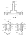
- FIG. 4 illustrates a cross sectional view of the base, axially extending shaft and collet of the chuck.
- FIGS. 5A and 5B illustrate cross sectional views of the collet with a disk that is, respectively, unsecured and secured to the chuck.
- FIG. 6 is an exploded perspective view of a chuck, in accordance with another embodiment of the present invention.
- FIG. 7 is a cross-sectional view of the chuck of FIG. 6 .
- FIGS. 1 and 2 are a perspective view and an exploded perspective view and FIG. 3 is a cross-sectional view of a chuck 100 for a disk 101 in accordance with one embodiment of the present invention.
- the chuck 100 includes a base 110 with an axially extending shaft 111 .
- a collet 112 at the end of the shaft 111 holds a disk 101 from the inside diameter of an aperture in the disk 101 .
- a sleeve 102 at least partially surrounds the collet 112 leaving the end of the collet 112 exposed to contact the inside diameter of the disk.
- the sleeve 102 limits the outward radial movement of the collet 112 by serving as a hard stop.
- the end 103 of the sleeve 102 serves as an annular shoulder (sometimes referred to as a Z-surface) upon which the disk 101 is seated as a reference surface.
- the chuck 100 includes an expander element, such as expander cap 104 , that is used to radially expand the collet 112 to contact and hold a disk.
- the expander cap 104 fits at least partially within a central opening of the collet 112 and includes a rounded fillet 105 that contacts beveled surfaces on the inside of fingers of the collet 112 to expand the collet 112 .
- other types of expander elements may be used.
- the expander element may be completely contained within the central opening of the collet 112 and is, thus, not a cap.
- the expander element e.g., expander cap 104
- the actuator 120 pulls the piston rod 106 axially towards the base 110 , which pulls the expander cap 104 into the collet 112 .
- the rounded fillet 105 on the expander cap 104 and beveled surfaces on the inside surfaces of the collet 112 translate the axial motion of the expander cap 104 into radial expansion of the collet 112 . In this manner, the collet 112 can be expanded to contact the inside diameter of a disk.
- the sleeve 102 limits the radial expansion of the collet 112 , thereby limiting the force that is applied on the collet 112 to the disk 101 .
- the expander cap 104 may have a beveled surface and the collet have the rounded fillet.
- both the collet and the expander cap may have beveled surfaces, but this will increase friction when attempting to expand the collet 112 .
- the actuator 120 is mounted in a cavity 116 within the base 110 .
- the actuator 120 may be a vacuum activated piston, as illustrated in FIGS. 2 and 3 , but any desired type of actuator may be used with chuck 100 , for example spring closed and air release.
- the vacuum activated actuator 120 includes a piston 122 and a piston cap 124 that is mounted to the piston 122 , e.g., by screws 126 .
- a seal 128 is held in between the piston 122 , the piston cap 124 , and an internal surface of the base 110 .
- the piston rod 106 is threadedly coupled to the piston 122 .
- the piston rod 106 is inserted through and guided by bearings 130 and 132 , which may be, e.g., jeweled bearings.
- the bearings 130 , 132 are held by a bearing mount 134 that is press fit or bonded inside the axially extending shaft 111 , e.g., using an epoxy, such as that produced by Hernon
- the sleeve 102 , expander cap 104 and the collet 112 are manufactured from non-magnetic materials, such as stainless steel, aluminum and possible plastic may be used, particularly for the expander cap. Additionally, the materials used for the collet 112 and the expander cap 104 should be dissimilar.
- FIG. 4 illustrates a cross sectional view of the base 110 and shaft 111 with the collet 112 .
- the base 110 has a generally cylindrical body that includes hollow central cavity 116 in which the actuator 120 (shown in FIGS. 2 and 3 ) is mounted.
- the axially extending shaft 111 includes a central bore 113 that is in communication with the central cavity 116 of the base 110 .
- the piston rod 106 along with the bearings 130 and 132 and bearing holder 134 , is positioned within the central bore 113 and connects the actuator 120 to the expander cap 104 (shown in FIGS. 1 and 2 ) when installed.
- the collet 112 is integrally formed at the end of the shaft 111 .
- the shaft 111 also includes an annular shelf 114 that the serves as a positioning stop for the sleeve 102 (shown in FIGS. 1 , 2 , and 3 ). Also illustrated in FIG. 4 are through holes and counter bores 118 in the base 110 for bolts or other connectors to mount the base 110 to a spindle (not shown) to rotate chuck 100 during operation. The bottom of the base 110 is lapped to form a good seal with the spindle when attached. The vacuum is applied to the cavity 116 and the actuator 120 by way of a through bore in the spindle to which the chuck 100 is attached during operation.
- the spindle may be any conventional spindle or an air bearing spindle, used in the industry, such as the types manufactured by Dover Instrument Corporation of Westboro, Mass. or ABT Inc., a division of KLA Tencor, of Swanzey, N.H.
- FIGS. 5A and 5B illustrate cross sectional views of the collet 112 at the end of the shaft 111 with a portion of a disk 101 and the sleeve 102 .
- the collet 112 includes a number of fingers 142 with annularly oriented outwardly extending projections 146 .
- the radially facing contact surfaces 148 of the projections 146 make contact with the inside diameter 101 ID of the disk 101 when the chuck 100 is closed on the disk 101 .
- each finger 142 includes a beveled surface 144 on the central opening to assist in translating axial movement of the expander cap 104 , illustrated by arrow 140 in FIG. 5A , to radial movement of the fingers 142 , illustrated by arrow 141 in FIG. 5A .
- FIG. 5A illustrates the collet 112 when the chuck 100 is closed, i.e., the disk 101 secured by the chuck 100 .
- the contact surfaces 148 of the fingers 142 contact the inside diameter 101 ID of the disk 101 to secure the disk 101 .
- the actuator 120 moves the expander cap 104 in the opposite direction and the fingers 142 of the collet 112 , which are biased radially inward, disengage with the inside diameter 101 D of the disk 101 .
- the sleeve 102 limits the outward radial travel of the fingers 142 , as illustrated in FIG. 5B , thereby limiting the stress that the fingers 142 may impart on the disk 101 .
- the fingers 142 impart an outward force on the inside diameter 101 ID of the disk 101 , as opposed to a downward clamping force, the fingers 142 generate little or no curvature or warping of the disk 101 .
- the contact surface 148 of the projections 146 may be slightly beveled downward, e.g., approximately 1° or less, to impart a small downward force on the disk 101 to help maintain the position of the disk 101 against the end of the sleeve 102 . Nevertheless, even with a beveled contact surface 148 , most of the force provided by the fingers 142 on the disk 101 is outward and, thus, there is little or no curvature or warping of the disk 101 .
- collet 112 provides a large approximately continuous area of contact on the inside diameter of the disk 101 , which further assists in limiting the curvature or warping of the disk 101 .
- the fingers 142 are manufactured to provide a spring force to bias the chuck 100 in an open position.
- the spring force of the fingers 142 should be less than the force applied by the actuator 120 , which is, e.g., approximately 3 to 3.5 pounds, but sufficient to open the chuck to release a disk when the vacuum is released.
- the fingers 142 may be manufactured with an appropriate spring force by one of ordinary skill in the art in light of the present disclosure and taking into considerations such as the number, thickness and material of fingers as well as the vacuum force applied by the spindle and friction coefficient between the collet 112 and the expander cap 104 .
- a spring inside the central bore 113 may be used to produce the desired open bias force.
- the spindle may apply a vacuum to close the chuck 100 and air pressure to open the chuck 100 .
- the chuck 100 may be biased closed, e.g., with a spring inside the central bore 113 , e.g., between the bearing mount 134 and/or the base 110 and the actuator 120 , may be used to produce the desired closed bias force.
- the spindle would apply air pressure to the actuator 120 to overcome the spring bias to open the chuck 100 .
- FIGS. 6 and 7 illustrate an exploded perspective view and a cross-sectional view of a chuck 200 for a disk 101 , in accordance with another embodiment of the present invention, like designated elements being the same.
- Chuck 200 includes cantilevered collet 240 that is formed separately from and is coupled to the base 210 .
- a sleeve 202 is mounted to the base 210 and in one embodiment is integrally formed with the base 210 as an axially extending shaft. As with sleeve 102 in FIG. 2 , the sleeve 202 includes an end 203 that serves as annular reference surface for the disk 101 .
- the collet 240 is positioned inside the sleeve 202 and is held in position by the bearing mount 234 , which also holds the bearings 230 and 232 , through which the piston rod 206 extends from the actuator 120 to the expander cap 204 .
- the bearing mount 234 may be press fit or bonded to a central bore in the base 210 .
- the collet 240 includes a plurality of fingers 242 that are annularly oriented with outwardly extending projection 246 having radially facing contact surfaces 248 .
- the collet 240 further includes a radial ring 250 with a center aperture 252 , through which a portion of the bearing mount 234 passes.
- the radial ring 250 is positioned at approximately the center of mass of each finger 242 .
- the fingers 242 are, thus, cantilevered with the radial ring 250 serving as the fulcra. Accordingly, it is desirable for the radial ring 250 to be as close as possible to the center of mass of the fingers 242 .
- the center of mass is approximately half of the axially extending length of each finger 242 .
- the distal end of the fingers 242 with respect to the expander cap 204 may be trimmed, e.g., to form beveled surface 256 , to place the center of mass of the fingers 242 at approximately the point of contact with the radial ring 250 .
- the radial ring 250 may include a plurality of radial slits 254 that coincide with the fingers 242 .
- the expander cap 204 or other type of expander element, includes a rounded fillet 205 that contacts the internal beveled surfaces 244 of the fingers 242 to translate axial movement of the expander cap 204 into radial movement of the fingers 242 .
- the actuator 120 pulls the piston rod 206 axially towards the base 210 , which pulls the expander cap 204 into the collet 240 thereby producing radial movement of the fingers 242 .
- the amount of outward movement of the fingers 242 and, thus, the static force applied to a disk 101 is controlled by the actuator 120 and the vacuum or air pressure supplied by the spindle (not shown) to which the chuck 200 is attached.
- the sleeve 202 may serve as a hard stop to limit the radial movement of the fingers 242 as described in reference to chuck 100 .
- the chuck 200 may be bias closed using spring 262 and opened using air pressure supplied from the spindle to the actuator 120 .
- the chuck 200 may be biased open using spring 264 , illustrated with dotted lines, and closed using a vacuum supplied from the spindle to the actuator 120 .
- the spring force supplied by the fingers 242 may bias the chuck 200 open, as discussed above.
Landscapes
- Engineering & Computer Science (AREA)
- Mechanical Engineering (AREA)
- Holding Or Fastening Of Disk On Rotational Shaft (AREA)
Abstract
Description
Claims (28)
Priority Applications (1)
| Application Number | Priority Date | Filing Date | Title |
|---|---|---|---|
| US11/686,569 US7958619B1 (en) | 2007-03-15 | 2007-03-15 | Disk chuck with radial force limiter |
Applications Claiming Priority (1)
| Application Number | Priority Date | Filing Date | Title |
|---|---|---|---|
| US11/686,569 US7958619B1 (en) | 2007-03-15 | 2007-03-15 | Disk chuck with radial force limiter |
Publications (1)
| Publication Number | Publication Date |
|---|---|
| US7958619B1 true US7958619B1 (en) | 2011-06-14 |
Family
ID=44121788
Family Applications (1)
| Application Number | Title | Priority Date | Filing Date |
|---|---|---|---|
| US11/686,569 Expired - Fee Related US7958619B1 (en) | 2007-03-15 | 2007-03-15 | Disk chuck with radial force limiter |
Country Status (1)
| Country | Link |
|---|---|
| US (1) | US7958619B1 (en) |
Cited By (8)
| Publication number | Priority date | Publication date | Assignee | Title |
|---|---|---|---|---|
| US20090014968A1 (en) * | 2007-07-11 | 2009-01-15 | Schenck Rotec Gmbh | Method and device for centering and clamping a workpiece in a balancing machine |
| US20120013081A1 (en) * | 2010-07-16 | 2012-01-19 | Kennametal Inc. | Clamping and releasing assembly |
| US8800997B1 (en) * | 2009-07-29 | 2014-08-12 | Hydra-Lock Corporation | Stepped collet |
| US20140252725A1 (en) * | 2013-03-07 | 2014-09-11 | Hon Hai Precision Industry Co., Ltd. | Clamping apparatus for cutting tool |
| CN104540626A (en) * | 2012-06-05 | 2015-04-22 | 罗伯特·博世有限公司 | Collet retention mechanism for a rotary tool |
| US9156139B1 (en) * | 2011-06-13 | 2015-10-13 | Donald L. Ekhoff | Disc spindle with flexible cap clamping |
| US9687913B1 (en) * | 2016-11-03 | 2017-06-27 | Lawrence D. Smith | I. D. collet |
| US20230375129A1 (en) * | 2022-05-23 | 2023-11-23 | Michael Nowling | Indicator Connection Adapter Device |
Citations (16)
| Publication number | Priority date | Publication date | Assignee | Title |
|---|---|---|---|---|
| US2398278A (en) * | 1944-04-27 | 1946-04-09 | Bailey Haskell | Adjustable stop for lathe spindles |
| US2507686A (en) * | 1947-08-08 | 1950-05-16 | Altmayer John | Arbor |
| US3360276A (en) * | 1965-06-10 | 1967-12-26 | John J Peffer | Automatic screw machine tube stock extension means |
| US3495844A (en) * | 1965-07-01 | 1970-02-17 | Gilbert C Davis | Chuck for rotary tool |
| US3583714A (en) * | 1968-11-27 | 1971-06-08 | Gleason Works | Chuck and collet for shank pinions and the like |
| US3587371A (en) * | 1968-12-11 | 1971-06-28 | John F Sherwood | Expanding arbor-collet |
| US3734513A (en) * | 1970-06-04 | 1973-05-22 | Kuroda Gauge Mfg | Straight chuck |
| US3768815A (en) * | 1972-06-21 | 1973-10-30 | Ibm | Apparatus for clamping and centering a flexible magnetic disk |
| US4755981A (en) * | 1987-01-27 | 1988-07-05 | Ekhoff Donald L | Spindle clamp for removable disks |
| US4958839A (en) | 1988-07-12 | 1990-09-25 | Guzik Technical Enterprises, Inc. | Disc clamp employing resilient cone for spreading balls |
| US5048005A (en) | 1989-10-10 | 1991-09-10 | Ekhoff Donald L | Spindle clamp having a unitary lock member |
| US5056082A (en) | 1989-06-12 | 1991-10-08 | Ekhoff Donald L | Apparatus for clamping removable disks |
| US5275424A (en) * | 1991-10-22 | 1994-01-04 | Nihon Micro Coating Co., Ltd. | Disk holding apparatus |
| US5560624A (en) * | 1994-09-02 | 1996-10-01 | Exclusive Design Company | Disk clamping collet system |
| US5644564A (en) | 1995-03-17 | 1997-07-01 | Phase Metrics | Vacuum chuck for rotating data discs |
| US6954330B2 (en) | 2001-12-04 | 2005-10-11 | Samsung Electronics, Co., Ltd. | Disk chuck |
-
2007
- 2007-03-15 US US11/686,569 patent/US7958619B1/en not_active Expired - Fee Related
Patent Citations (17)
| Publication number | Priority date | Publication date | Assignee | Title |
|---|---|---|---|---|
| US2398278A (en) * | 1944-04-27 | 1946-04-09 | Bailey Haskell | Adjustable stop for lathe spindles |
| US2507686A (en) * | 1947-08-08 | 1950-05-16 | Altmayer John | Arbor |
| US3360276A (en) * | 1965-06-10 | 1967-12-26 | John J Peffer | Automatic screw machine tube stock extension means |
| US3495844A (en) * | 1965-07-01 | 1970-02-17 | Gilbert C Davis | Chuck for rotary tool |
| US3583714A (en) * | 1968-11-27 | 1971-06-08 | Gleason Works | Chuck and collet for shank pinions and the like |
| US3587371A (en) * | 1968-12-11 | 1971-06-28 | John F Sherwood | Expanding arbor-collet |
| US3734513A (en) * | 1970-06-04 | 1973-05-22 | Kuroda Gauge Mfg | Straight chuck |
| US3768815A (en) * | 1972-06-21 | 1973-10-30 | Ibm | Apparatus for clamping and centering a flexible magnetic disk |
| US4755981A (en) * | 1987-01-27 | 1988-07-05 | Ekhoff Donald L | Spindle clamp for removable disks |
| US4958839A (en) | 1988-07-12 | 1990-09-25 | Guzik Technical Enterprises, Inc. | Disc clamp employing resilient cone for spreading balls |
| US5056082A (en) | 1989-06-12 | 1991-10-08 | Ekhoff Donald L | Apparatus for clamping removable disks |
| US5048005A (en) | 1989-10-10 | 1991-09-10 | Ekhoff Donald L | Spindle clamp having a unitary lock member |
| US5275424A (en) * | 1991-10-22 | 1994-01-04 | Nihon Micro Coating Co., Ltd. | Disk holding apparatus |
| US5560624A (en) * | 1994-09-02 | 1996-10-01 | Exclusive Design Company | Disk clamping collet system |
| US5785324A (en) * | 1994-09-02 | 1998-07-28 | Exclusive Design Company | Full surface texture collet system |
| US5644564A (en) | 1995-03-17 | 1997-07-01 | Phase Metrics | Vacuum chuck for rotating data discs |
| US6954330B2 (en) | 2001-12-04 | 2005-10-11 | Samsung Electronics, Co., Ltd. | Disk chuck |
Cited By (13)
| Publication number | Priority date | Publication date | Assignee | Title |
|---|---|---|---|---|
| US8359727B2 (en) * | 2007-07-11 | 2013-01-29 | Schenck Rotec Gmbh | Method and device for centering and clamping a workpiece in a balancing machine |
| US20130093147A1 (en) * | 2007-07-11 | 2013-04-18 | Schenck Rotec Gmbh | Method and device for centering and clamping a workpiece in a balancing machine |
| US8517390B2 (en) * | 2007-07-11 | 2013-08-27 | Schenck Ro Tec Gmbh | Method and device for centering and clamping a workpiece in a balancing machine |
| US20090014968A1 (en) * | 2007-07-11 | 2009-01-15 | Schenck Rotec Gmbh | Method and device for centering and clamping a workpiece in a balancing machine |
| US8800997B1 (en) * | 2009-07-29 | 2014-08-12 | Hydra-Lock Corporation | Stepped collet |
| US20120013081A1 (en) * | 2010-07-16 | 2012-01-19 | Kennametal Inc. | Clamping and releasing assembly |
| US9156139B1 (en) * | 2011-06-13 | 2015-10-13 | Donald L. Ekhoff | Disc spindle with flexible cap clamping |
| CN104540626B (en) * | 2012-06-05 | 2018-09-07 | 罗伯特·博世有限公司 | Collet chuck holding mechanism for rotating tool |
| CN104540626A (en) * | 2012-06-05 | 2015-04-22 | 罗伯特·博世有限公司 | Collet retention mechanism for a rotary tool |
| US20140252725A1 (en) * | 2013-03-07 | 2014-09-11 | Hon Hai Precision Industry Co., Ltd. | Clamping apparatus for cutting tool |
| US9687913B1 (en) * | 2016-11-03 | 2017-06-27 | Lawrence D. Smith | I. D. collet |
| US20230375129A1 (en) * | 2022-05-23 | 2023-11-23 | Michael Nowling | Indicator Connection Adapter Device |
| US12013081B2 (en) * | 2022-05-23 | 2024-06-18 | Michael Nowling | Indicator connection adapter device |
Similar Documents
| Publication | Publication Date | Title |
|---|---|---|
| US7958619B1 (en) | Disk chuck with radial force limiter | |
| JP4038911B2 (en) | Disk rotation drive mechanism and disk drive device | |
| KR0180231B1 (en) | Data recording disk chuck mechanism | |
| US20080030109A1 (en) | Motor and storage disk device | |
| US7802273B2 (en) | Turntable assembly | |
| GB2313633A (en) | Conic fluid bearing | |
| US7721445B2 (en) | Thrust plate, method of manufacturing thereof, motor using the thrust plate, and the data storage disk drive using the motor | |
| JPS63107438A (en) | Bearing apparatus | |
| US7499244B2 (en) | Disk holder for off-line servo-track writer | |
| US20090155011A1 (en) | Rotary tapered tool holder with adapter sleeve | |
| US5828519A (en) | Disk clamp device and disk drive | |
| US4887175A (en) | Disc driving unit | |
| US9156139B1 (en) | Disc spindle with flexible cap clamping | |
| US20060232880A1 (en) | Mounting system for a storage media disc | |
| JPS6124050A (en) | Chucking device of magnetic disc recording and reproducing device | |
| JPH10196645A (en) | Sliding bearing device and its related technique | |
| JP2003016707A (en) | Method and apparatus for clamping disk | |
| US20060119988A1 (en) | Head stack assembly incorporating a pivot assembly having solid lubrication | |
| JPH0310461B2 (en) | ||
| JPH048151A (en) | Method of machining spindle motor | |
| JPS5936373A (en) | Reproducer for disk-shaped recording medium | |
| JP2003173645A (en) | Apparatus for aligning and fixing disk and method for the same | |
| JPH06106401A (en) | Method for cutting body of rotation | |
| JPH10230427A (en) | Work holding mechanism | |
| JPH09320226A (en) | Disk holder |
Legal Events
| Date | Code | Title | Description |
|---|---|---|---|
| AS | Assignment |
Owner name: MAGNETIC RECORDING SOLUTIONS, INC., CALIFORNIA Free format text: ASSIGNMENT OF ASSIGNORS INTEREST;ASSIGNOR:PLETSCHET, TIMOTHY J.;REEL/FRAME:019017/0916 Effective date: 20070314 |
|
| AS | Assignment |
Owner name: XYRATEX TECHNOLOGY LIMITED, UNITED KINGDOM Free format text: ASSIGNMENT OF ASSIGNORS INTEREST;ASSIGNOR:MAGNETIC RECORDING SOLUTIONS, INC.;REEL/FRAME:026145/0746 Effective date: 20101122 |
|
| STCF | Information on status: patent grant |
Free format text: PATENTED CASE |
|
| FEPP | Fee payment procedure |
Free format text: PAYOR NUMBER ASSIGNED (ORIGINAL EVENT CODE: ASPN); ENTITY STATUS OF PATENT OWNER: LARGE ENTITY |
|
| FPAY | Fee payment |
Year of fee payment: 4 |
|
| MAFP | Maintenance fee payment |
Free format text: PAYMENT OF MAINTENANCE FEE, 8TH YEAR, LARGE ENTITY (ORIGINAL EVENT CODE: M1552); ENTITY STATUS OF PATENT OWNER: LARGE ENTITY Year of fee payment: 8 |
|
| FEPP | Fee payment procedure |
Free format text: MAINTENANCE FEE REMINDER MAILED (ORIGINAL EVENT CODE: REM.); ENTITY STATUS OF PATENT OWNER: LARGE ENTITY |
|
| LAPS | Lapse for failure to pay maintenance fees |
Free format text: PATENT EXPIRED FOR FAILURE TO PAY MAINTENANCE FEES (ORIGINAL EVENT CODE: EXP.); ENTITY STATUS OF PATENT OWNER: LARGE ENTITY |
|
| STCH | Information on status: patent discontinuation |
Free format text: PATENT EXPIRED DUE TO NONPAYMENT OF MAINTENANCE FEES UNDER 37 CFR 1.362 |
|
| FP | Lapsed due to failure to pay maintenance fee |
Effective date: 20230614 |