US7938068B2 - Toy track section with alignment feature - Google Patents
Toy track section with alignment feature Download PDFInfo
- Publication number
- US7938068B2 US7938068B2 US12/200,489 US20048908A US7938068B2 US 7938068 B2 US7938068 B2 US 7938068B2 US 20048908 A US20048908 A US 20048908A US 7938068 B2 US7938068 B2 US 7938068B2
- Authority
- US
- United States
- Prior art keywords
- wheel
- train
- track
- bearing
- section
- Prior art date
- Legal status (The legal status is an assumption and is not a legal conclusion. Google has not performed a legal analysis and makes no representation as to the accuracy of the status listed.)
- Expired - Fee Related, expires
Links
- 238000010586 diagram Methods 0.000 description 3
- 239000002991 molded plastic Substances 0.000 description 3
- 206010012411 Derailment Diseases 0.000 description 1
- 238000012986 modification Methods 0.000 description 1
- 230000004048 modification Effects 0.000 description 1
Images


Classifications
-
- A—HUMAN NECESSITIES
- A63—SPORTS; GAMES; AMUSEMENTS
- A63H—TOYS, e.g. TOPS, DOLLS, HOOPS OR BUILDING BLOCKS
- A63H19/00—Model railways
- A63H19/30—Permanent way; Rails; Rail-joint connections
-
- A—HUMAN NECESSITIES
- A63—SPORTS; GAMES; AMUSEMENTS
- A63H—TOYS, e.g. TOPS, DOLLS, HOOPS OR BUILDING BLOCKS
- A63H18/00—Highways or trackways for toys; Propulsion by special interaction between vehicle and track
-
- A—HUMAN NECESSITIES
- A63—SPORTS; GAMES; AMUSEMENTS
- A63H—TOYS, e.g. TOPS, DOLLS, HOOPS OR BUILDING BLOCKS
- A63H19/00—Model railways
- A63H19/34—Bridges; Stations; Signalling systems
-
- Y—GENERAL TAGGING OF NEW TECHNOLOGICAL DEVELOPMENTS; GENERAL TAGGING OF CROSS-SECTIONAL TECHNOLOGIES SPANNING OVER SEVERAL SECTIONS OF THE IPC; TECHNICAL SUBJECTS COVERED BY FORMER USPC CROSS-REFERENCE ART COLLECTIONS [XRACs] AND DIGESTS
- Y10—TECHNICAL SUBJECTS COVERED BY FORMER USPC
- Y10T—TECHNICAL SUBJECTS COVERED BY FORMER US CLASSIFICATION
- Y10T29/00—Metal working
- Y10T29/49—Method of mechanical manufacture
- Y10T29/49826—Assembling or joining
Definitions
- the present invention relates to a track section for a toy train track.
- the present invention relates to a track section that is configured to align a train that is placed on the track section.
- a train set is a common children's toy.
- a train set generally includes a track and one or more toy trains or cars that can travel or be moved by a child along the track.
- Some toy trains have wheels on each side of a train body that are designed to contact and roll along surfaces, such as rails, on the track.
- wheels on rails results in trains being difficult to place on the track for children.
- the wheels on the toy train can be difficult to align with the rails on the track.
- Many toy train cars include two axles, such as a front axle and a rear axle, with two wheels coupled to each axle.
- Each set of wheels is required to be precisely positioned on the track to achieve proper alignment.
- the train is usually unable to run or be moved along the track.
- a toy train may include several cars. If even one of the wheels on one of the cars is improperly positioned on the track, the toy train as a whole will not travel along the track properly.
- the toy train set includes a train and a track that can be supported by a play surface.
- the train track includes multiple sections along which a train can travel.
- the track includes an alignment or guide section that has a guide portion.
- the guide portion is the portion of the alignment section that directly contacts or is engaged by the train and that is configured to align the train.
- the guide portion of the track includes first and second wheel bearing surfaces for supporting at least a portion of the weight of the train.
- the guide portion also includes first and second guide surfaces.
- the guide surfaces can be located between the bearing surfaces.
- the first and second guide surfaces are disposed or orientated in an inclined manner.
- the guide portion can include an engagement surface or portion for receiving or engaging with a propulsion or drive member of a train.
- the engagement surface is located between the first and second guide surfaces.
- the trains can have one car, such as an engine, or can have two or more cars.
- Each car has multiple sets of wheels and each set of wheels includes two wheels that are connected to each other by a transverse axle.
- a car includes a front wheel set and a rear wheel set, with each of the front and rear wheel sets including a wheel on opposite sides of the body of the cars of the train.
- a train that is placed on the guide portion of the alignment section is automatically aligned for travel along the remainder of the track.
- a train that has been separated from the track is placed so that its wheels contact a portion of the guide surfaces of the track section.
- the guide surfaces are inclined or angled, and the weight of the train and/or the forward motion of the train cause the wheels of the train to travel downwardly and outwardly along the particular inclined guide surface.
- Each of the wheels of the train travels outwardly until it reaches the lower edge of the guide surface and engages with the corresponding bearing surface.
- wheel sets are sized and configured relative to the track so that when the left wheels of a train car are at the lower edge of a guide surface on the left side, the right wheels are at the lower edge of a guide surface on the right side.
- the train wheels roll along the lower edges of the inclined surfaces and on the wheel bearing surfaces.
- the inclined surface of each of the first and second guide surfaces urge a wheel outwardly if it moves inwardly against and engages the guide surface. Therefore, after alignment, the wheels tend to remain properly aligned as the train travels along the wheel bearing surfaces.
- FIG. 1 illustrates a schematic block diagram of an embodiment of a toy train and track section in accordance with an aspect of the present invention.
- FIG. 2 illustrates a schematic block diagram of an alternative embodiment of a toy train and track section in accordance with an aspect of the present invention.
- FIG. 3 illustrates a top perspective view of an embodiment of the toy train track system in accordance with an aspect of the present invention.
- FIG. 4 illustrates a top perspective view of a train entering an alignment section of the track system illustrated in FIG. 3 .
- FIG. 5 illustrates a top perspective view of the alignment section illustrated in FIG. 4 .
- FIG. 6 illustrates a top perspective view of a portion of the track system illustrated in FIG. 4 .
- FIG. 7A illustrates an end view of an exemplary train wheel set separated from an alignment or guide section in accordance with an aspect of the present invention.
- FIGS. 7B and 7C illustrate end views of the train wheel set illustrated in FIG. 7A in engagement and in alignment with the alignment section, respectively.
- FIG. 7D illustrates an end view of an alternative embodiment of an alignment section in accordance with an aspect of the present invention.
- FIG. 8 illustrates a perspective view of an embodiment of an entry track section that can be used with the track system illustrated in FIG. 3 .
- FIG. 9 illustrates an enlarged perspective view of the entry section illustrated in FIG. 8 .
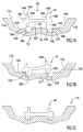
- FIG. 10 illustrates a top view of an alternative embodiment of a track section in accordance with the present invention.
- FIG. 11 illustrates a cross-sectional view of the track section illustrated in FIG. 10 taken along the line “ 11 - 11 .”
- FIG. 12 illustrates a perspective view of a toy vehicle being placed on a track section in accordance with the present invention.
- the toy train 10 includes a body or body portion 12 with wheels 14 and 16 movably coupled to the body 12 .
- the body 12 can be configured so that it resembles the body of a toy train.
- the wheels 14 and 16 can be left side and right side wheels, respectively, that are coupled to an axle that is rotatably mounted to the body 12 .
- the toy train 10 may include two additional wheels, which are not illustrated for ease of reference.
- the track section is configured to align toy train 10 so that it can travel along a toy track.
- the track section 20 includes a body or body portion 22 that has a guide portion 24 and a bearing portion 26 .
- the guide portion 24 and the bearing portion 26 are formed on the body 22 and may be different surfaces.
- the track section 20 is a molded plastic article with the guide portion 24 and the bearing portion 26 formed thereon.
- the guide portion 24 and/or the bearing portion 26 can be formed separately from the body 22 and subsequently coupled thereto.
- the toy train 10 can be moved proximate to the track section 20 so that wheels 14 and 16 engage the track section 20 .
- either or both of the wheels 14 and 16 can be placed into engagement with the guide portion 24 .
- the guide portion 24 is configured to direct the wheels 14 and 16 toward the bearing portion 26 so that the wheels 14 and 16 can travel along the bearing portion 26 and the toy train 10 can move along the track section 20 .
- the track section 20 is coupled to other portions of a toy track so that the toy train 10 can travel along the track.
- the toy train 30 includes a body 32 that has wheels 34 and 36 movably coupled thereto.
- Toy train 30 also includes a drive mechanism 38 .
- the drive mechanism 38 includes a motor (not shown), a power supply (not shown), and an engaging member.
- the engaging member can be a continuous track that is driven by the output of the motor.
- the engagement member can have one or more projections extending therefrom that is moved relative to the body of the toy train 30 .
- the drive mechanism may include a rotatably mounted wheel body that has one or more projections around its circumference that are configured to engage the track.
- a belt with one or more projections can be driven by the drive mechanism.
- the track section 40 includes a body 42 with guide portions 44 and 46 and bearing portions 48 and 50 .
- the guide portions 44 and 46 are configured to be engaged by the wheels 34 and 36 and to direct the wheels 34 and 36 so that they move toward the bearing portions 48 and 50 of the track section 40 .
- the body 42 can include a drive portion 52 that is configured to be engaged by the drive mechanism 38 .
- the drive portion 52 may be grooves or recesses that can be engaged by one or more projections of the drive mechanism 38 .
- the drive portion 52 may be a smooth surface that can be engaged by the drive mechanism 38 .
- the drive portion 52 may be several projections that can be engaged by the drive mechanism 38 .
- the relative locations of the guide portions 44 and 46 and the bearing portions 48 and 50 can vary. In one embodiment, the guide portions 44 and 46 are disposed between the bearing portions 48 and 50 . In another embodiment, the bearing portions 48 and 50 are disposed between the guide portions 44 and 46 .
- the toy train track set 100 includes several components.
- the quantity, size and configuration of the components that are used to form the toy train track set can vary.
- the toy train track set 100 includes a toy train 140 and a track 160 . While toy train 140 is illustrated as having three cars, the toy train 140 can have any quantity of cars in different embodiments.
- the track 160 is supported on a play surface 101 .
- the track 160 includes multiple sections that are connected together at the ends of adjacent sections. In one embodiment, the different portions of the track 160 are formed out of molded plastic articles.
- the track 160 includes an alignment section 110 and a travel section 105 .
- the travel section 105 is the remaining portion of track 160 (excluding alignment section 110 ) around which the train 140 travels.
- the alignment section 110 and a toy train 140 are illustrated.
- the alignment section 110 can be referred to alternatively as the alignment portion as well.
- the toy train 140 is entering the alignment section 110 from the travel portion 105 of the track 160 .
- Each car of the toy train 140 has multiple sets of wheels on which the train 140 moves.
- Each set of wheels includes two wheels (a front wheel set and a rear wheel set) that are connected by a transverse axle.
- Each wheel set includes a left wheel and a right wheel.
- wheels 145 A and 145 B are illustrated in contact with alignment section 110 . Even though wheels 145 A and 145 B are discussed below, each set of wheels of toy train 140 function in a similar manner, and for ease of reference and discussion, only wheels 145 A and 145 B are discussed.
- FIGS. 5 , 6 , and 7 A show perspective, top, and end views of an embodiment of the alignment section 110 , respectively.
- the alignment section or alignment portion 110 includes a body 119 that has first and second side walls 114 A and 114 B that extend along the body 119 .
- Side walls 114 A and 114 B are positioned longitudinally along opposite sides of alignment section 110 and extend from end 111 to end 113 of the alignment section 110 .
- Alignment section 110 also includes a guide portion or section 112 .
- Guide portion 112 is the part of the alignment section 110 that train 140 contacts as the train 140 travels on alignment section 110 . In this embodiment, guide portion 112 is positioned along the longitudinal direction between side walls 114 A and 114 B.
- the top of side walls 114 A and 114 B extend above guide portion 112 and above the wheels of toy train 140 placed on the alignment section 110 .
- the height of the side walls 114 A and 114 B limits the extent to which the train 140 can be misaligned by tilting or movement in a side-to-side direction.
- the side walls 114 A and 114 B form a receiving area or travel space 115 therebetween in which the toy train 140 can be placed and can travel.
- the side walls 114 A and 114 B include slanted inner wall surfaces 117 A and 117 B, which together with guide portion 112 form the travel space or receiving area 115 .
- the inner wall surfaces 117 A and 117 B are slanted outwardly and upwardly, thereby providing the travel space 115 with a general V-shape to allow easy placement of the toy train 140 by a child.
- the inner wall surfaces 117 A and 117 B can have the same shape or configuration or have a different shape or configuration from each other.
- each of wheels 145 A and 145 B of the toy train 140 engage the guide portion 112 of the alignment section 110 .
- each of wheels 145 A and 145 B includes surfaces that engage a portion of the track. These surfaces on the wheels 145 A and 145 B can be referred to as bearing surfaces and for each wheel, the bearing surface is located on the bottom of each wheel. Another such bearing surface is formed on an extension of the wheel along the direction of the axle.
- the guide portion 112 includes first and second wheel bearing surfaces 126 A and 126 B (see FIGS. 5-7A ).
- the wheel bearing surfaces 126 A and 126 B can be referred to alternatively as bearing sections or bearing portions.
- Wheel bearing surfaces 126 A and 126 B are configured to be engaged by the lower edges of the wheels 145 A and 145 B and that bear at least a portion of the weight of the toy train 140 .
- Wheel bearing surfaces 126 A and 126 B extend along the length of the alignment section 110 from end 111 to end 113 .
- the width of the wheel bearing surfaces 126 A and 126 B can vary in different embodiments and can be any size provided that the wheels 145 A and 145 B can travel therealong.
- the wheel bearing surfaces 126 A and 126 B are generally or substantially planar or horizontal surfaces. In another embodiment, the wheel bearing surfaces 126 A and 126 B can be uneven surfaces. In yet another embodiment, the wheel bearing surfaces 126 A and 126 B can be inclined or disposed at an angle relative to a support surface.
- the guide portion 112 also includes guide surfaces or sides 122 A and 122 B that extend from end 111 to end 113 (see FIG. 5 ).
- the guide surfaces 122 A and 122 B are disposed or oriented at an angle with respect to a horizontal support surface and the wheel being surfaces 126 A and 126 B. In other words, the guide surfaces 122 A and 122 B are inclined.
- the guide surfaces 122 A and 122 B slant or are angled downwardly toward the wheel bearing surfaces 126 A and 126 B of the alignment section 110 .
- the particular angles at which the guide surfaces 122 A and 122 B are inclined can vary in different embodiments.
- the guide surfaces 122 A and 122 B can be steep in some embodiments and in other embodiments can be sloped gradually.
- the guide surfaces 122 A and 122 B are located between the wheel bearing surfaces 126 A and 126 B.
- the wheel bearing surfaces 126 A and 126 B are located on the outer sides of the guide surfaces 122 A and 122 B with respect to the longitudinal axis 125 of the alignment section 110 .
- each of the wheel bearing surfaces 126 A and 126 B are located adjacent to one of the inclined guide surfaces 122 A and 122 B and form a substantially continuous surface with the particular inclined guide surface.
- the side walls 114 A and 114 B can extend upwardly from the wheel bearing surfaces 126 A and 126 B, respectively.
- the guide portion or section 112 also includes an engagement portion or surface 118 .
- the engagement surface 118 is the part of the guide portion 112 that is engaged by a drive mechanism of the toy train 140 .
- the engagement between the drive mechanism of the toy train 140 and the engagement portion 118 enables the drive mechanism to propel the toy train 140 along the alignment section 110 .
- the engagement surface 118 is formed as a raised surface with adjacent alternating grooves or recesses 121 formed therein.
- the grooves 121 are located between and adjacent to the inclined guide surfaces 122 A and 122 B.
- the engagement surface 118 can have a different structure for use with the drive mechanism, such as a different quantity or configuration of the grooves.
- the grooves 121 can be replaced by projections along the guide section 112 .
- the upper surface of the engagement surface 118 is aligned with the upper ends of the inclined guide surfaces 122 A and 122 B. If the drive mechanism of train 140 is a toothed gear or component, the teeth of the drive mechanism can engage the grooves 121 of the engagement surface 118 to propel the toy train 140 .
- the guide portion 112 also includes outer guide surfaces 125 A and 125 B.
- the outer guide surfaces 125 A and 125 B are substantially vertical and serve as outer positioning limits for the wheels 145 A and 145 B of the toy train 140 .
- the outer guide surfaces 125 A and 125 B are positioned on the outer edges of wheel bearing surfaces 126 A and 126 B and extend along the length of alignment section 110 .
- the guide portion 112 includes guide bearing surfaces 124 A and 124 B.
- each of wheels 145 A and 145 B includes multiple bearing surfaces. A portion of each of the wheels 145 A and 145 B can engage the first and second guide bearing surfaces 124 A and 124 B.
- guide bearing surfaces 124 A and 124 B bear the weight of the toy train 140 .
- Each of the side walls 114 A and 114 B extends upwardly from one of the guide bearing surfaces 124 A and 124 B and has an inner surface. Each inner surface includes a portion of which that is slanted downwardly and inwardly to align the toy train 140 as it is placed on the track section 110 .
- the guide bearing surfaces 124 A and 124 B are generally or substantially planar or horizontal surfaces. In another embodiment, the guide bearing surfaces 146 A and 146 B can be uneven surfaces. In yet another embodiment, the guide bearing surfaces 146 A and 146 B can be inclined or disposed at an angle relative to a support surface.
- converging guides proximate to each end of alignment section 110 are converging guides. As shown in FIG. 5 , proximate to end 111 of the alignment section 110 are converging guides 128 A and 128 B. A top view of the converging guides 128 A and 128 B is illustrated in FIG. 6 . It is to be understood that similarly structured converging guides are proximate to end 113 of the alignment section 110 .
- the converging guides 128 A and 128 B include inwardly slanted surfaces or portions 130 A and 130 B, respectively, which are extensions of outer guide surfaces 125 A and 125 B. As shown, the converging guide surfaces 130 A and 130 B are directed slightly inwardly toward each other.
- the distance between converging guide surface 130 A and converging guide surface 130 B varies and is less than the distance between outer guide surface 125 A and outer guide surface 125 B.
- the distance or transverse distance between the outer guide surfaces 125 A and 125 B proximate to a center of the alignment section 110 is greater than the distance or transverse distance between the guide surfaces 130 A and 130 B proximate to either end 111 or 113 of the alignment section 110 .
- Converging guides 128 A and 128 B align the wheels 145 A and 145 B of the toy train 140 with the track 160 to ensure that the toy train 140 is accurately transferred from the alignment section 110 to remainder of the track 160 .
- track 160 includes track guides 161 A and 161 B.
- the track guides 161 A and 161 B include track bearing surfaces 164 A and 164 B and inner track surfaces 166 A and 166 B, respectively.
- the track 160 can be a molded plastic article that is configured to resemble the rails of a track.
- the bearing guide surfaces 124 A and 124 B of the alignment section 110 align and transfer the wheels of the toy train 140 to the track bearing surfaces 164 A and 164 B via the converging guides 128 A and 128 B.
- track bearing surfaces 164 A and 164 B assume the weight bearing function that bearing guide surfaces 124 A and 124 B were performing.
- outer guide surfaces 125 A and 125 B direct the wheels 145 A and 145 B to inner track surfaces 166 A and 166 B.
- inner track surfaces 166 A and 166 B assume the wheel guiding functions that the outer guide surfaces 125 A and 125 B were performing.
- FIGS. 7A-7C show end views of a pair of wheels 145 A and 145 B and the alignment section 110 .
- wheels 145 A and 145 B are illustrated as moving into engagement with the guide portion 112 of the alignment section 110 . While only wheels 145 A and 145 B are illustrated, it is to be understood that any of the sets of wheels for a toy train or the cars of a toy train function and can be moved in a similar manner.
- the wheel set 144 is first positioned over the guide portion 112 of the alignment section 110 .
- the wheel set 144 has two wheels 145 A and 145 B that are connected by an axle 152 .
- the wheels 145 A and 145 B include wheel bearing surfaces 146 A and 146 B, outer wall bearing surfaces 148 A and 148 B, and inner wheel guide surfaces 150 A and 150 B.
- the alignment of toy train 140 on guide section 112 is illustrated with respect to wheel set 144 for ease of reference. However, it is to be understood that wheel set 144 is coupled to the body of a toy train 140 connected thereto.
- FIG. 7A shows the wheel set 144 disposed in a misaligned/non-centered position over the guide portion 112 .
- Lines 149 A and 149 B show the locations at which the wheels 145 A and 145 B would contact the inclined guide surfaces 122 A and 122 B and the wheel bearing surfaces 126 A and 126 B if wheel set 144 were lowered along the direction of arrow 156 .
- FIG. 7B shows a position of the wheel set 144 based on the positioning of the wheel set 144 along the lines 149 A and 149 B in FIG. 7A .
- the inner wheel guide surface or edge 150 B contacts inclined guide surface 122 B and wheel bearing surface or edge 146 A contacts guide bearing surface 124 A.
- the weight and motion of the toy train 140 will cause the wheel 145 B to slide or move along the guide surface 122 B along the direction of arrow 157 .
- the weight and/or motion of the toy train 140 directs wheel 145 B outwardly and downwardly until wheel 145 B contacts wheel bearing surface 126 B.
- the portions of wheel 145 A that are in contact with guide portion 112 slide until the wheel set 144 is located in the manner shown in FIG. 7C in engagement with wheel bearing surface 126 A.
- the track section 300 includes a body 310 with an upper surface 312 and side walls 314 and 316 .
- the body 310 includes guide bearing surfaces 318 and 320 that are configured to be engaged by portions or extensions on the wheels 145 A and 145 B of a toy train 140 .
- the alignment section 300 includes a guide portion 322 that is configured to align a toy train 140 that is placed on the section 300 .
- the guide portion 322 includes inclined guide surfaces 324 and 326 and wheel bearing surfaces 330 and 332 . In this embodiment, the inclined guide surfaces 324 and 326 are disposed on the outer sides of the wheel bearing surfaces 330 and 332 .
- the guide surfaces 324 and 326 are configured to direct the wheels 145 A and 145 B of a toy train 140 placed on track section 300 into engagement with the wheel bearing surfaces 330 and 332 .
- the alignment section 300 also includes a drive portion 328 that is configured to be engaged with a drive mechanism of the toy train 140 .
- FIG. 8 illustrates an embodiment of a section of track and entry section in accordance with an aspect of the present invention.
- the track section 160 is connected to an entry section 200 that is configured to allow a toy train 140 to travel along a play surface 202 , such a floor or carpet, and onto entry section 200 . Once the toy train 140 is on the entry section 200 , it travels from the entry section 200 in an aligned manner onto the track section 160 .
- the entry section 200 includes a ramp 220 designed to smoothly accept transfer of wheels of a toy vehicle or train from the play surface 202 .
- the toy train 140 travels from play surface 202 onto the ramp 220 between ramp guide surfaces 227 A and 227 B.
- the ramp guide surfaces 227 A and 227 B are directed so as to converge toward each other to funnel or direct the toy train 140 toward the guide portion 212 of the ramp 220 .
- the guide portion 212 can include several features that correspond to features of the guide portion 112 of the alignment section 110 .
- the engagement surface or portion 218 , the inclined guide surfaces 222 A and 222 B, the guide bearing surfaces 224 A and 224 B, the outer guide surfaces (only surface 225 A being shown), and the wheel bearing surfaces (only surface 226 A being shown) correspond to the corresponding structures discussed above for the alignment section 110 .
- the guide portion 212 includes an inclined engagement surface 219 .
- Inclined engagement surface 219 is positioned on the ramp 220 adjacent to and aligned with the engagement surface 218 .
- the engagement surface 219 is inclined to accommodate the drive mechanism of toy train 140 as the ramp guide surfaces 227 A and 227 B guide and direct the toy train 140 toward guide portion 212 .
- the track section 300 has a curved shape or configuration.
- the track section 300 may include a body 310 with an engagement surface or portion 320 with spaced apart recesses or grooves 322 therealong.
- the track section 300 includes a guide portion that is formed by guide surfaces 330 and 332 which angled toward bearing surfaces 340 and 342 as shown in FIG. 11 .
- the bearing surfaces 340 and 342 are configured so that wheels of a toy vehicle placed on the track section 300 can move therealong.
- Side bearing surfaces 350 and 352 are disposed on the outer sides of bearing surfaces 340 and 342 .
- the body 310 can include side walls or side wall portions 312 and 314 that have inner surfaces 316 and 318 , respectively.
- the inner surfaces 316 and 318 are oriented to face inwardly toward the guides surfaces 330 and 332 .
- the track section 300 may have multiple curves and be in the shape of a letter “S.”
- the toy vehicle 400 has the configuration of a toy train.
- the toy vehicle 400 has a body 410 with side portions that have outer surfaces (only side portion 412 with side surface 414 is illustrated for ease of reference).
- Movably coupled to the body 410 are several wheels, each of which includes a flange or flange portion.
- front wheels 420 and 422 , and rear wheel 424 include flanges or flange portions 430 , 432 , and 434 , respectively.
- the track section 110 may include an engagement surface 118 with guides surfaces 122 A and 122 B. As the track section 110 has been described previously, only some of the components are illustrated in FIG. 12 and discussed relative thereto.
- track section 110 has a guide bearing surface 124 B, an outer guide surface 125 B, a wheel bearing surface 126 B, and an inner wall surface 117 B that is formed on the side wall 114 B.
- the inner wall surface 117 B is used to position the toy vehicle 400 so that the wheel flanges, such as flange 432 , do not rest on top of the guide bearing surfaces, such as guide bearing surface 124 B.
- the body 410 of the toy vehicle 400 actually contacts the side wall 114 B and in particular, the inner wall surface 117 B.
- the distance or dimension “A” in FIG. 12 is the distance between the outer side surface 414 of the vehicle body 410 and the outside of wheel flange 432 . As shown, the distance or dimension “A” is greater than the width dimension “B” of the guide bearing surface 124 B. The larger dimension “A” prevents the wheel flange 432 from being placed on the guide bearing surface 124 B, which otherwise would result in the wheel flange not engaging the particular guide surfaces 122 A and 122 B and the toy vehicle 400 not being aligned on the track section 110 .
- the dimensions “A” and “B” can vary in different embodiments so long as dimension “A” is greater than dimension “B.” While dimensions “A” and “B” are illustrated in FIG. 12 relative to one side of the body 410 , the engagement of an outer surface of the vehicle body 410 against surface 117 A of side wall 114 A on the other side of the vehicle 400 and the track section 110 is the same.
- a different type of vehicle such as a plane, boat, car, or spacecraft, can be used in place of the toy train 140 .
- multiple parts may be integrated (e.g., inclined guide surface 122 may be integrated with engagement surface 118 by creating slots/teeth in inclined guide surface 122 ).
- the alignment section 110 may function without an engagement surface or portion.
Abstract
Description
Claims (21)
Priority Applications (3)
| Application Number | Priority Date | Filing Date | Title |
|---|---|---|---|
| US12/200,489 US7938068B2 (en) | 2008-08-28 | 2008-08-28 | Toy track section with alignment feature |
| CA002676505A CA2676505A1 (en) | 2008-08-28 | 2009-08-24 | Toy track section with alignment feature |
| MX2009009118A MX2009009118A (en) | 2008-08-28 | 2009-08-26 | Toy track section with alignment feature. |
Applications Claiming Priority (1)
| Application Number | Priority Date | Filing Date | Title |
|---|---|---|---|
| US12/200,489 US7938068B2 (en) | 2008-08-28 | 2008-08-28 | Toy track section with alignment feature |
Publications (2)
| Publication Number | Publication Date |
|---|---|
| US20100056020A1 US20100056020A1 (en) | 2010-03-04 |
| US7938068B2 true US7938068B2 (en) | 2011-05-10 |
Family
ID=41726155
Family Applications (1)
| Application Number | Title | Priority Date | Filing Date |
|---|---|---|---|
| US12/200,489 Expired - Fee Related US7938068B2 (en) | 2008-08-28 | 2008-08-28 | Toy track section with alignment feature |
Country Status (3)
| Country | Link |
|---|---|
| US (1) | US7938068B2 (en) |
| CA (1) | CA2676505A1 (en) |
| MX (1) | MX2009009118A (en) |
Cited By (5)
| Publication number | Priority date | Publication date | Assignee | Title |
|---|---|---|---|---|
| US20130221119A1 (en) * | 2012-02-23 | 2013-08-29 | John Dewey Jobe | Controlled-friction track for gravity race cars |
| USD741418S1 (en) | 2014-09-02 | 2015-10-20 | Mega Brands Inc. | Track element |
| USD741417S1 (en) | 2014-09-02 | 2015-10-20 | Mega Brands Inc. | Track element |
| USD741957S1 (en) | 2014-09-02 | 2015-10-27 | Mega Brands Inc. | Track element |
| DE102015120345A1 (en) * | 2015-11-24 | 2017-05-24 | Paul Vahle Gmbh & Co. Kg | An insertion device for the carriage of a data transmission system with a slot waveguide system |
Families Citing this family (2)
| Publication number | Priority date | Publication date | Assignee | Title |
|---|---|---|---|---|
| US11439921B2 (en) | 2018-06-25 | 2022-09-13 | Universal City Studios Llc | Multi-dimensional bogie and track system |
| CN109228645B (en) * | 2018-10-24 | 2024-02-09 | 深圳市威利特自动化设备有限公司 | Printing production system |
Citations (28)
| Publication number | Priority date | Publication date | Assignee | Title |
|---|---|---|---|---|
| US2068403A (en) | 1936-06-12 | 1937-01-19 | Albin L Ekstrom | Vehicular apparatus |
| US2383940A (en) | 1939-09-13 | 1945-09-04 | Minner Walter | Track for toy vehicles |
| US2493010A (en) | 1945-06-04 | 1950-01-03 | William E Mcdonald | Track layout for loading and unloading |
| US2590317A (en) | 1948-05-25 | 1952-03-25 | Henderson Walter | Track locating device for toy trains |
| US3074647A (en) | 1958-10-22 | 1963-01-22 | Lionel Corp | Toy track structure |
| US3218757A (en) | 1964-03-24 | 1965-11-23 | Transogram Company Inc | Powered wheel vehicle and track assembly |
| US3442047A (en) | 1966-03-21 | 1969-05-06 | Marx & Co Louis | Vehicle guiding toy |
| US3514895A (en) * | 1967-03-24 | 1970-06-02 | Mattel Inc | Material handling toy and track system |
| US3610525A (en) | 1968-03-18 | 1971-10-05 | David James Townsend | Vehicle aligner |
| US3628725A (en) * | 1970-01-16 | 1971-12-21 | Mattel Inc | Compact toy lap counter |
| US3643865A (en) | 1969-05-19 | 1972-02-22 | Wolfgang Mutz | Vehicle track for use in toy building kits |
| USD258225S (en) | 1978-12-11 | 1981-02-10 | Rawson Harold J | Toy railroad car railer or similar article |
| US4355807A (en) | 1981-01-23 | 1982-10-26 | Aurora Products Canada Limited | Pivotable ramp device for track games |
| US4395843A (en) | 1981-08-26 | 1983-08-02 | Cpg Products Corp. | Toy vehicle and track with a reduced amount of resistance therebetween |
| EP0097731A1 (en) | 1982-06-26 | 1984-01-11 | Fukushiro Miura | Electric rerailer |
| US4493265A (en) * | 1980-12-29 | 1985-01-15 | Fukushiro Miura | Electric rerailer for a model railway |
| US4496100A (en) * | 1982-10-18 | 1985-01-29 | Mattel, Inc. | Flexible track |
| USRE32106E (en) | 1967-05-04 | 1986-04-08 | Toy track and vehicle therefor | |
| US4585166A (en) | 1984-10-25 | 1986-04-29 | Mattel, Inc. | Collapsible toy automobile race course |
| US4715843A (en) | 1985-09-20 | 1987-12-29 | Mattel, Inc. | Toy vehicle playset |
| USD344310S (en) | 1992-11-24 | 1994-02-15 | Interlego A.G. | Rail element for a toy train set |
| US5297484A (en) * | 1991-07-03 | 1994-03-29 | Train Products, Inc. | Vehicle guidance track system |
| US5791253A (en) * | 1996-05-30 | 1998-08-11 | Hasbro, Inc. | Toy vehicle track |
| US6601774B1 (en) * | 2002-06-11 | 2003-08-05 | Mark P. Kasimoff | Toy track system |
| US7051948B2 (en) * | 2002-10-08 | 2006-05-30 | Battat Incorporated | Flexible track for a toy vehicle |
| US20070259600A1 (en) * | 2005-06-16 | 2007-11-08 | Jonathan Bedford | Play set with toy vehicle track and carriage |
| US7302894B2 (en) | 2005-03-31 | 2007-12-04 | Belanger, Inc. | Curved entry guide rails for car wash conveyor |
| US20080105156A1 (en) * | 2004-11-15 | 2008-05-08 | Gert Olsen | Rail Element To A Toy Railway |
-
2008
- 2008-08-28 US US12/200,489 patent/US7938068B2/en not_active Expired - Fee Related
-
2009
- 2009-08-24 CA CA002676505A patent/CA2676505A1/en not_active Abandoned
- 2009-08-26 MX MX2009009118A patent/MX2009009118A/en active IP Right Grant
Patent Citations (29)
| Publication number | Priority date | Publication date | Assignee | Title |
|---|---|---|---|---|
| US2068403A (en) | 1936-06-12 | 1937-01-19 | Albin L Ekstrom | Vehicular apparatus |
| US2383940A (en) | 1939-09-13 | 1945-09-04 | Minner Walter | Track for toy vehicles |
| US2493010A (en) | 1945-06-04 | 1950-01-03 | William E Mcdonald | Track layout for loading and unloading |
| US2590317A (en) | 1948-05-25 | 1952-03-25 | Henderson Walter | Track locating device for toy trains |
| US3074647A (en) | 1958-10-22 | 1963-01-22 | Lionel Corp | Toy track structure |
| US3218757A (en) | 1964-03-24 | 1965-11-23 | Transogram Company Inc | Powered wheel vehicle and track assembly |
| US3442047A (en) | 1966-03-21 | 1969-05-06 | Marx & Co Louis | Vehicle guiding toy |
| US3514895A (en) * | 1967-03-24 | 1970-06-02 | Mattel Inc | Material handling toy and track system |
| USRE32106E (en) | 1967-05-04 | 1986-04-08 | Toy track and vehicle therefor | |
| US3610525A (en) | 1968-03-18 | 1971-10-05 | David James Townsend | Vehicle aligner |
| US3643865A (en) | 1969-05-19 | 1972-02-22 | Wolfgang Mutz | Vehicle track for use in toy building kits |
| US3628725A (en) * | 1970-01-16 | 1971-12-21 | Mattel Inc | Compact toy lap counter |
| USD258225S (en) | 1978-12-11 | 1981-02-10 | Rawson Harold J | Toy railroad car railer or similar article |
| US4493265A (en) * | 1980-12-29 | 1985-01-15 | Fukushiro Miura | Electric rerailer for a model railway |
| US4355807A (en) | 1981-01-23 | 1982-10-26 | Aurora Products Canada Limited | Pivotable ramp device for track games |
| US4395843A (en) | 1981-08-26 | 1983-08-02 | Cpg Products Corp. | Toy vehicle and track with a reduced amount of resistance therebetween |
| EP0097731A1 (en) | 1982-06-26 | 1984-01-11 | Fukushiro Miura | Electric rerailer |
| US4496100A (en) * | 1982-10-18 | 1985-01-29 | Mattel, Inc. | Flexible track |
| US4585166A (en) | 1984-10-25 | 1986-04-29 | Mattel, Inc. | Collapsible toy automobile race course |
| US4715843A (en) | 1985-09-20 | 1987-12-29 | Mattel, Inc. | Toy vehicle playset |
| US5297484A (en) * | 1991-07-03 | 1994-03-29 | Train Products, Inc. | Vehicle guidance track system |
| USD344310S (en) | 1992-11-24 | 1994-02-15 | Interlego A.G. | Rail element for a toy train set |
| US5791253A (en) * | 1996-05-30 | 1998-08-11 | Hasbro, Inc. | Toy vehicle track |
| US6601774B1 (en) * | 2002-06-11 | 2003-08-05 | Mark P. Kasimoff | Toy track system |
| US7051948B2 (en) * | 2002-10-08 | 2006-05-30 | Battat Incorporated | Flexible track for a toy vehicle |
| US20080105156A1 (en) * | 2004-11-15 | 2008-05-08 | Gert Olsen | Rail Element To A Toy Railway |
| US7302894B2 (en) | 2005-03-31 | 2007-12-04 | Belanger, Inc. | Curved entry guide rails for car wash conveyor |
| US20070259600A1 (en) * | 2005-06-16 | 2007-11-08 | Jonathan Bedford | Play set with toy vehicle track and carriage |
| US7517272B2 (en) * | 2005-06-16 | 2009-04-14 | Jonathan Bedford | Play set with toy vehicle track and carriage |
Cited By (6)
| Publication number | Priority date | Publication date | Assignee | Title |
|---|---|---|---|---|
| US20130221119A1 (en) * | 2012-02-23 | 2013-08-29 | John Dewey Jobe | Controlled-friction track for gravity race cars |
| US8708245B2 (en) * | 2012-02-23 | 2014-04-29 | John Dewey Jobe | Controlled-friction track for gravity race cars |
| USD741418S1 (en) | 2014-09-02 | 2015-10-20 | Mega Brands Inc. | Track element |
| USD741417S1 (en) | 2014-09-02 | 2015-10-20 | Mega Brands Inc. | Track element |
| USD741957S1 (en) | 2014-09-02 | 2015-10-27 | Mega Brands Inc. | Track element |
| DE102015120345A1 (en) * | 2015-11-24 | 2017-05-24 | Paul Vahle Gmbh & Co. Kg | An insertion device for the carriage of a data transmission system with a slot waveguide system |
Also Published As
| Publication number | Publication date |
|---|---|
| CA2676505A1 (en) | 2010-02-28 |
| MX2009009118A (en) | 2010-03-22 |
| US20100056020A1 (en) | 2010-03-04 |
Similar Documents
| Publication | Publication Date | Title |
|---|---|---|
| US7938068B2 (en) | Toy track section with alignment feature | |
| CN100434318C (en) | Sliding treadboard | |
| CN106743128B (en) | Shopping trolley conveying system | |
| US7581502B2 (en) | Rail vehicle system and transportation method of using the rail vehicle system | |
| US9212454B2 (en) | Branching device and center guide-type track-based transportation system | |
| US7093543B2 (en) | Carriage type conveyor | |
| US8790152B2 (en) | Ramp for a ride-on toy | |
| CN103991788A (en) | Rail crane climbing mechanism | |
| US4357877A (en) | Toy train | |
| US11459706B1 (en) | Rapid transit system with wheel in track design | |
| EP1846131B1 (en) | Rail element for a toy railway | |
| JP5395445B2 (en) | Railcar traverser | |
| JP5603131B2 (en) | Monorail car traverser system and separation system by rack and pinion drive system | |
| CN109641600B (en) | Vehicle turning device and track using the same | |
| US20230294743A1 (en) | Rapid transit system with wheel in track design | |
| JP6367428B1 (en) | Passenger conveyor | |
| JPS601009Y2 (en) | Connecting device between a truck and a trolley in a truck conveyor | |
| JPS6024676Y2 (en) | Floor-conveyor trolley | |
| JPH0114537Y2 (en) | ||
| JP3266598B2 (en) | Assembled track members | |
| JPS592009Y2 (en) | conveyor equipment | |
| JPS5839100B2 (en) | tow conveyor device | |
| JPH0522494Y2 (en) | ||
| JP2740356B2 (en) | Conveyor for car parking platform | |
| JPH0123881Y2 (en) |
Legal Events
| Date | Code | Title | Description |
|---|---|---|---|
| AS | Assignment |
Owner name: MATTEL, INC.,CALIFORNIA Free format text: ASSIGNMENT OF ASSIGNORS INTEREST;ASSIGNORS:PARKER, KENNETH G.;PHINNEY, RAY C.;REEL/FRAME:021664/0347 Effective date: 20081006 Owner name: MATTEL, INC., CALIFORNIA Free format text: ASSIGNMENT OF ASSIGNORS INTEREST;ASSIGNORS:PARKER, KENNETH G.;PHINNEY, RAY C.;REEL/FRAME:021664/0347 Effective date: 20081006 |
|
| STCF | Information on status: patent grant |
Free format text: PATENTED CASE |
|
| FPAY | Fee payment |
Year of fee payment: 4 |
|
| AS | Assignment |
Owner name: BANK OF AMERICA, N.A., AS COLLATERAL AGENT FOR SEC Free format text: SECURITY INTEREST;ASSIGNOR:MATTEL, INC.;REEL/FRAME:044941/0241 Effective date: 20171220 |
|
| MAFP | Maintenance fee payment |
Free format text: PAYMENT OF MAINTENANCE FEE, 8TH YEAR, LARGE ENTITY (ORIGINAL EVENT CODE: M1552); ENTITY STATUS OF PATENT OWNER: LARGE ENTITY Year of fee payment: 8 |
|
| AS | Assignment |
Owner name: BANK OF AMERICA, N.A. AS ADMINISTRATIVE AGENT, NORTH CAROLINA Free format text: PATENT SECURITY AGREEMENT;ASSIGNOR:MATTEL, INC.;REEL/FRAME:061451/0850 Effective date: 20220915 Owner name: MATTEL, INC., CALIFORNIA Free format text: RELEASE OF GRANT OF SECURITY INTEREST IN INTELLECTUAL PROPERTY RIGHTS;ASSIGNOR:BANK OF AMERICA, N.A., AS AGENT;REEL/FRAME:061462/0537 Effective date: 20220915 |
|
| FEPP | Fee payment procedure |
Free format text: MAINTENANCE FEE REMINDER MAILED (ORIGINAL EVENT CODE: REM.); ENTITY STATUS OF PATENT OWNER: LARGE ENTITY |
|
| LAPS | Lapse for failure to pay maintenance fees |
Free format text: PATENT EXPIRED FOR FAILURE TO PAY MAINTENANCE FEES (ORIGINAL EVENT CODE: EXP.); ENTITY STATUS OF PATENT OWNER: LARGE ENTITY |
|
| STCH | Information on status: patent discontinuation |
Free format text: PATENT EXPIRED DUE TO NONPAYMENT OF MAINTENANCE FEES UNDER 37 CFR 1.362 |
|
| FP | Lapsed due to failure to pay maintenance fee |
Effective date: 20230510 |
|
| AS | Assignment |
Owner name: MATTEL, INC., CALIFORNIA Free format text: RELEASE OF GRANT OF SECURITY INTEREST IN INTELLECTUAL PROPERTY RIGHTS;ASSIGNOR:BANK OF AMERICA, N.A., AS ADMINISTRATIVE AGENT;REEL/FRAME:065266/0778 Effective date: 20231003 |