US7934482B2 - Liquid-cooled composite piston - Google Patents
Liquid-cooled composite piston Download PDFInfo
- Publication number
- US7934482B2 US7934482B2 US11/991,522 US99152206A US7934482B2 US 7934482 B2 US7934482 B2 US 7934482B2 US 99152206 A US99152206 A US 99152206A US 7934482 B2 US7934482 B2 US 7934482B2
- Authority
- US
- United States
- Prior art keywords
- piston
- cooling channel
- contact surface
- radially
- pin
- Prior art date
- Legal status (The legal status is an assumption and is not a legal conclusion. Google has not performed a legal analysis and makes no representation as to the accuracy of the status listed.)
- Active, expires
Links
- 239000002131 composite material Substances 0.000 title claims description 6
- 238000001816 cooling Methods 0.000 claims abstract description 30
- 238000003801 milling Methods 0.000 claims description 4
- 229910001018 Cast iron Inorganic materials 0.000 description 2
- OKTJSMMVPCPJKN-UHFFFAOYSA-N Carbon Chemical compound [C] OKTJSMMVPCPJKN-UHFFFAOYSA-N 0.000 description 1
- 229910000831 Steel Inorganic materials 0.000 description 1
- XAGFODPZIPBFFR-UHFFFAOYSA-N aluminium Chemical compound [Al] XAGFODPZIPBFFR-UHFFFAOYSA-N 0.000 description 1
- 229910052782 aluminium Inorganic materials 0.000 description 1
- 230000000295 complement effect Effects 0.000 description 1
- 230000006835 compression Effects 0.000 description 1
- 238000007906 compression Methods 0.000 description 1
- 229910002804 graphite Inorganic materials 0.000 description 1
- 239000010439 graphite Substances 0.000 description 1
- 239000010959 steel Substances 0.000 description 1
Images


Classifications
-
- F—MECHANICAL ENGINEERING; LIGHTING; HEATING; WEAPONS; BLASTING
- F02—COMBUSTION ENGINES; HOT-GAS OR COMBUSTION-PRODUCT ENGINE PLANTS
- F02F—CYLINDERS, PISTONS OR CASINGS, FOR COMBUSTION ENGINES; ARRANGEMENTS OF SEALINGS IN COMBUSTION ENGINES
- F02F3/00—Pistons
- F02F3/0015—Multi-part pistons
- F02F3/0023—Multi-part pistons the parts being bolted or screwed together
-
- F—MECHANICAL ENGINEERING; LIGHTING; HEATING; WEAPONS; BLASTING
- F02—COMBUSTION ENGINES; HOT-GAS OR COMBUSTION-PRODUCT ENGINE PLANTS
- F02F—CYLINDERS, PISTONS OR CASINGS, FOR COMBUSTION ENGINES; ARRANGEMENTS OF SEALINGS IN COMBUSTION ENGINES
- F02F3/00—Pistons
-
- F—MECHANICAL ENGINEERING; LIGHTING; HEATING; WEAPONS; BLASTING
- F02—COMBUSTION ENGINES; HOT-GAS OR COMBUSTION-PRODUCT ENGINE PLANTS
- F02F—CYLINDERS, PISTONS OR CASINGS, FOR COMBUSTION ENGINES; ARRANGEMENTS OF SEALINGS IN COMBUSTION ENGINES
- F02F3/00—Pistons
- F02F3/16—Pistons having cooling means
- F02F3/20—Pistons having cooling means the means being a fluid flowing through or along piston
- F02F3/22—Pistons having cooling means the means being a fluid flowing through or along piston the fluid being liquid
Definitions
- the invention relates to a liquid-cooled composite piston in accordance with the preamble of the claim.
- a liquid-cooled composite piston that consists of an upper part forming the piston head and a lower part having the piston skirt is known from the Offenlegungsschrift [examined patent application published for public scrutiny] DE 41 31 275 A1.
- the upper part and the lower part are connected with one another by means of an expansion screw, whereby a sleeve is disposed between the head of the expansion screw and a collar of the lower part that serves to support the expansion screw, which sleeve has radial bores by way of which cooling oil that has collected in an inner cooling chamber can drain off.
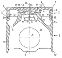
- FIG. 1 a section through a liquid-cooled composite piston, along a plane that lies in the major thrust side/minor thrust side direction of the piston, with a side view of the hexagonal nut according to the invention
- FIG. 2 a section through the piston along a plane that lies in the direction of the longitudinal axis of the pin bore, with a section through the hexagonal nut according to the invention.
- FIGS. 1 and 2 A two-part, liquid-cooled composite piston 1 is shown in FIGS. 1 and 2 , which piston consists of an upper part 2 and a lower part 3 .
- the upper part 2 and the lower part 3 can be produced from aluminum, steel, or from cast iron with spheroidal graphite (GGG cast iron according to DIN 1693).
- a piston crown 4 delimits the axial top of the upper part 2 .
- a ring wall 5 is formed onto the outer edge of the piston crown 4 , the outer surface of which wall forms a top land 6 on the piston crown side, which is followed, on the skirt side, by a ring belt 7 having ring grooves for accommodating piston rings not shown in the figures.
- Two pin bosses 8 , 8 ′ each having a pin bore 9 , 9 ′ are disposed on the underside of the lower part 3 that faces away from piston crown 4 .
- the radially outer face surfaces 29 , 29 ′ of the pin bosses 8 , 8 ′ are offset radially inward with regard to the ring wall 5 .
- the pin bosses 8 , 8 ′ are connected with one another by way of skirt elements 10 , 10 ′.
- the upper part 2 and the lower part 3 of the piston 1 are connected with one another by way of a radially inner, ring-shaped contact surface 11 and by way of a radially outer, ring-shaped contact surface 12 , disposed concentric to the former.
- the radially outer contact surface 12 is formed by the piston-crown-side face surface of a support land 14 that runs radially on the outside, and is formed on, on the piston crown side, partially onto the skirt elements 10 , 10 ′ ( FIG. 1 ) and partly onto the pin bosses 8 , 8 ′ ( FIG. 2 ).
- the contact surface 12 has the shape of a step 30 directed radially inward and axially in the direction of the piston crown 4 .
- the piston 1 its upper part 2 and its lower part 3 can be aligned coaxially with one another in that the inner side of the lower face of the ring wall 5 has a cylindrical recess 31 , the inside shape of which is complementary to the shape of the step 30 of the outer contact surface 12 , so that during assembly of the piston 1 , the step 30 can be introduced into the recess 31 , thereby achieving coaxial alignment of the upper part and lower part of the piston 1 .
- the inner contact surface 11 is formed by the ring-shaped, piston-crown-side face of a lower part foot 15 that runs on the circumference radially within the support land 14 , and, like the support land 14 , is formed on, partly onto the skirt elements 10 , 10 ′ ( FIG. 1 ) and partly onto the pin bosses 8 , 8 ′ ( FIG. 2 ).
- the upper part 2 of the piston 1 rests on the inner contact surface 11 by way of a formed-on part 32 disposed on the side of the piston facing away from the piston crown, whereby the face of the formed-on part 32 that faces away from the piston crown rests on the inner contact surface 11 , and at least approximately has the same radial diameter as the inner contact surface 11 .
- An outer cooling channel 13 disposed in the piston-crown-side edge region of the piston 1 is formed by the upper part 2 and by the lower part 3 of the piston 1 , the radially outer delimitation of which channel is formed partly by the ring wall 5 and partly by the support land 14 , the radially inner delimitation by the lower part foot 15 , the axially upper delimitation by the piston crown 4 , and the axially lower delimitation by the lower part 3 of the piston 1 .
- Cooling oil is passed into the outer cooling channel 13 by way of at least one oil feed channel 16 that opens into the piston interior 28 .
- the piston 1 has another ring-shaped inner cooling channel 18 , disposed coaxial to the piston axis 17 , which has a lesser radial diameter than the outer cooling channel 13 , and is disposed within the outer cooling channel 13 , seen in the radial direction.
- the inner cooling channel 18 is delimited by the piston crown 4 , radially on the outside partly by the lower part foot 15 and partly by a formed-on part 33 that narrows conically in the direction facing away from the piston crown, disposed radially on the inside of the lower part foot 15 , axially at the bottom by a hexagonal nut 19 that will be explained in greater detail below, and radially on the inside by a pin 20 configured cylindrically, which is disposed on the underside of the piston crown 4 , coaxial to the piston axis 17 .
- the outer cooling channel 13 is connected with the inner cooling channel 18 by way of groove-shaped overflow channels 22 , 22 ′ worked into the inner contact surface 11 .
- the outer cooling channel 13 and the inner cooling channel 18 can also be connected with one another by way of bores made in the lower part foot 15 .
- the mantle surface of the pin 20 has an end region facing away from the piston crown, having an outside thread 23 ( FIG. 2 ), which corresponds to the inside thread 34 of the hexagonal nut 19 , so that the hexagonal nut 19 can be screwed onto the outside thread 23 of the pin 20 .
- the hexagonal nut 19 consists of a threaded part 24 having the inside thread 34 and an outer surface that is hexagonal, seen in the radially horizontal cross-section, and a collar 25 formed onto it on the piston crown side, which, in the present exemplary embodiment, has two radially disposed bores or millings 26 , 27 that lie opposite one another, which connect the inner cooling channel 18 with the piston interior 28 .
Landscapes
- Engineering & Computer Science (AREA)
- Chemical & Material Sciences (AREA)
- Combustion & Propulsion (AREA)
- Mechanical Engineering (AREA)
- General Engineering & Computer Science (AREA)
- Physics & Mathematics (AREA)
- Fluid Mechanics (AREA)
- Pistons, Piston Rings, And Cylinders (AREA)
Abstract
Description
- 1 piston
- 2 upper part of the
piston 1 - 3 lower part of the
piston 1 - 4 piston crown
- 5 ring wall
- 6 top land
- 7 ring belt
- 8, 8′ pin boss
- 9, 9′ pin bore
- 10, 10′ skirt element
- 11 inner contact surface
- 12 outer contact surface
- 13 outer cooling channel
- 14 support land
- 15 lower part foot
- 16 oil feed channel
- 17 piston axis
- 18 inner cooling channel
- 19 hexagonal nut
- 20 pin
- 22, 22′ overflow channel
- 23 outside thread of the
pin 20 - 24 threaded part of the
hexagonal nut 19 - 25 collar of the hexagonal nut
- 26, 27 bore (milling) in the
collar 25 of thehexagonal nut 19 - 28 piston interior
- 29, 29′ face surfaces of the
pin bosses - 30 step of the
outer contact surface 12 - 31 recess in the face of the
ring wall 5 - 32, 33 formed-on part
- 34 inside thread of the hexagonal nut
Claims (1)
Applications Claiming Priority (3)
| Application Number | Priority Date | Filing Date | Title |
|---|---|---|---|
| DE102005042003A DE102005042003A1 (en) | 2005-09-05 | 2005-09-05 | Built, liquid cooled flask |
| DE102005042003 | 2005-09-05 | ||
| PCT/DE2006/001548 WO2007028364A1 (en) | 2005-09-05 | 2006-09-02 | Liquid-cooled assembled piston |
Publications (2)
| Publication Number | Publication Date |
|---|---|
| US20090139481A1 US20090139481A1 (en) | 2009-06-04 |
| US7934482B2 true US7934482B2 (en) | 2011-05-03 |
Family
ID=37460180
Family Applications (1)
| Application Number | Title | Priority Date | Filing Date |
|---|---|---|---|
| US11/991,522 Active 2028-03-27 US7934482B2 (en) | 2005-09-05 | 2006-09-02 | Liquid-cooled composite piston |
Country Status (7)
| Country | Link |
|---|---|
| US (1) | US7934482B2 (en) |
| EP (1) | EP1922478B1 (en) |
| JP (1) | JP4838848B2 (en) |
| KR (1) | KR101279843B1 (en) |
| CN (1) | CN100572784C (en) |
| DE (1) | DE102005042003A1 (en) |
| WO (1) | WO2007028364A1 (en) |
Cited By (6)
| Publication number | Priority date | Publication date | Assignee | Title |
|---|---|---|---|---|
| US20090151556A1 (en) * | 2007-12-14 | 2009-06-18 | Wolfgang Issler | Two-part piston for an internal combustion engine |
| US20100108000A1 (en) * | 2008-11-05 | 2010-05-06 | Rainer Scharp | Multi-part piston for an internal combustion engine and method for its production |
| US20100107999A1 (en) * | 2008-11-05 | 2010-05-06 | Rainer Scharp | Multi-part piston for an internal combustion engine and method for its production |
| US20100108015A1 (en) * | 2008-11-05 | 2010-05-06 | Rainer Scharp | Multi-part piston for an internal combustion engine |
| US20110265744A1 (en) * | 2008-11-04 | 2011-11-03 | Ks Kolbenschmidt Gmbh | Internal combustion engine piston with cooling channel said piston comprising a sealing element sealing the cooling channel |
| US20140260957A1 (en) * | 2013-03-14 | 2014-09-18 | Martyn Hempston | Piston assembly with preloaded support surfaces |
Families Citing this family (8)
| Publication number | Priority date | Publication date | Assignee | Title |
|---|---|---|---|---|
| DE102008056203A1 (en) * | 2008-11-06 | 2010-05-12 | Mahle International Gmbh | Multi-part piston for an internal combustion engine and method for its production |
| EP2543849A1 (en) | 2010-03-02 | 2013-01-09 | Toyota Jidosha Kabushiki Kaisha | Combustion pressure control device |
| US10449621B2 (en) * | 2014-05-01 | 2019-10-22 | Mahle International Gmbh | Magnetic arc welded piston assembly |
| DE102016001926A1 (en) * | 2016-02-18 | 2017-08-24 | Man Truck & Bus Ag | Piston for a reciprocating internal combustion engine |
| DE102021128790A1 (en) | 2021-11-05 | 2023-05-11 | Dr. Ing. H.C. F. Porsche Aktiengesellschaft | Piston assembly for an internal combustion engine |
| DE102021128787A1 (en) | 2021-11-05 | 2023-05-11 | Dr. Ing. H.C. F. Porsche Aktiengesellschaft | Pistons for an internal combustion engine |
| CN114645798B (en) * | 2022-03-14 | 2023-02-28 | 北京理工大学 | A piston pin hole bushing structure |
| USD1108688S1 (en) * | 2024-09-16 | 2026-01-06 | Yidan SUN | Dual linear light |
Citations (11)
| Publication number | Priority date | Publication date | Assignee | Title |
|---|---|---|---|---|
| FR1037133A (en) | 1951-05-16 | 1953-09-15 | Engine piston improvements | |
| US3358657A (en) | 1964-12-29 | 1967-12-19 | Hispano Suiza Sa | Pistons of internal combustion engines |
| US3465651A (en) | 1968-02-13 | 1969-09-09 | Alco Products Inc | Composite pistons |
| DE2936630A1 (en) | 1979-09-11 | 1981-03-26 | Mtu Motoren- Und Turbinen-Union Friedrichshafen Gmbh, 88045 Friedrichshafen | IC engine bolted construction piston - has crown plate with rounded or conical face bearing against piston body |
| US4375782A (en) * | 1979-04-10 | 1983-03-08 | Karl Schmidt Gmbh | Composite piston for internal combustion engines |
| US5081968A (en) * | 1990-07-31 | 1992-01-21 | Borgo Nova Spa | Pistons for an internal combustion engine |
| DE4131275A1 (en) | 1991-09-20 | 1993-03-25 | Mahle Gmbh | Sectional fluid-cooled piston for I.C.- engine - has head accommodating piston rings connected by central screw arrangement to piston shaft |
| EP0604223A1 (en) | 1992-12-23 | 1994-06-29 | GENERAL ELECTRIC CANADA, Inc. | Piston cap for a diesel engine |
| US6729291B1 (en) | 2002-12-06 | 2004-05-04 | Mahle Gmbh | Multipart cooled piston for an internal combustion engine |
| US20080121204A1 (en) * | 2004-11-30 | 2008-05-29 | Rainer Scharp | Multipart, Cooled Piston For a Combustion Engine |
| US20090260593A1 (en) * | 2005-09-01 | 2009-10-22 | Dieter Messmer | Two-part piston for an internal combustion engine |
Family Cites Families (8)
| Publication number | Priority date | Publication date | Assignee | Title |
|---|---|---|---|---|
| DE3719469A1 (en) * | 1987-06-11 | 1988-12-29 | Mahle Gmbh | BUILT LIQUID-COOLED PISTON FOR COMBUSTION ENGINES |
| KR19990031997U (en) * | 1997-12-31 | 1999-07-26 | 정몽규 | Piston cooling structure |
| DE19846496A1 (en) * | 1998-10-09 | 2000-04-13 | Mahle Gmbh | Internal combustion engine piston with base, beneath which is oil-fed cooling chamber with lower limit formed by plate fixed to piston, pressure-loaded devices pressing elastically deformable plate in direction of piston base |
| DE10022035A1 (en) * | 2000-05-05 | 2001-11-08 | Mahle Gmbh | Internal combustion engine with built piston; has piston with base and lower part connected by screw having device in head to transfer oil from connecting rod to cooling chamber in piston |
| DE10210570A1 (en) * | 2002-03-09 | 2003-09-18 | Mahle Gmbh | Multi-part cooled piston for an internal combustion engine |
| CN2601323Y (en) * | 2002-04-05 | 2004-01-28 | 曾庆生 | Support friction loose-proof unlocking bolt |
| CN2653140Y (en) * | 2003-06-27 | 2004-11-03 | 绵阳新晨动力机械有限公司 | Oil sump of petrol engine |
| CN2667182Y (en) * | 2003-10-09 | 2004-12-29 | 中国北车集团大连机车研究所 | Steel head aluminium apron piston for 280/285 serial natural gas engine |
-
2005
- 2005-09-05 DE DE102005042003A patent/DE102005042003A1/en not_active Withdrawn
-
2006
- 2006-09-02 WO PCT/DE2006/001548 patent/WO2007028364A1/en not_active Ceased
- 2006-09-02 EP EP06775919A patent/EP1922478B1/en active Active
- 2006-09-02 CN CNB2006800323162A patent/CN100572784C/en not_active Expired - Fee Related
- 2006-09-02 US US11/991,522 patent/US7934482B2/en active Active
- 2006-09-02 KR KR1020087006566A patent/KR101279843B1/en not_active Expired - Fee Related
- 2006-09-02 JP JP2008529461A patent/JP4838848B2/en not_active Expired - Fee Related
Patent Citations (13)
| Publication number | Priority date | Publication date | Assignee | Title |
|---|---|---|---|---|
| FR1037133A (en) | 1951-05-16 | 1953-09-15 | Engine piston improvements | |
| US3358657A (en) | 1964-12-29 | 1967-12-19 | Hispano Suiza Sa | Pistons of internal combustion engines |
| DE1476111A1 (en) | 1964-12-29 | 1970-10-08 | Snecma | Pistons for internal combustion engines |
| US3465651A (en) | 1968-02-13 | 1969-09-09 | Alco Products Inc | Composite pistons |
| US4375782A (en) * | 1979-04-10 | 1983-03-08 | Karl Schmidt Gmbh | Composite piston for internal combustion engines |
| DE2936630A1 (en) | 1979-09-11 | 1981-03-26 | Mtu Motoren- Und Turbinen-Union Friedrichshafen Gmbh, 88045 Friedrichshafen | IC engine bolted construction piston - has crown plate with rounded or conical face bearing against piston body |
| US5081968A (en) * | 1990-07-31 | 1992-01-21 | Borgo Nova Spa | Pistons for an internal combustion engine |
| DE4131275A1 (en) | 1991-09-20 | 1993-03-25 | Mahle Gmbh | Sectional fluid-cooled piston for I.C.- engine - has head accommodating piston rings connected by central screw arrangement to piston shaft |
| EP0604223A1 (en) | 1992-12-23 | 1994-06-29 | GENERAL ELECTRIC CANADA, Inc. | Piston cap for a diesel engine |
| US6729291B1 (en) | 2002-12-06 | 2004-05-04 | Mahle Gmbh | Multipart cooled piston for an internal combustion engine |
| DE10257022A1 (en) | 2002-12-06 | 2004-06-17 | Mahle Gmbh | Multi-part cooled piston for an internal combustion engine |
| US20080121204A1 (en) * | 2004-11-30 | 2008-05-29 | Rainer Scharp | Multipart, Cooled Piston For a Combustion Engine |
| US20090260593A1 (en) * | 2005-09-01 | 2009-10-22 | Dieter Messmer | Two-part piston for an internal combustion engine |
Non-Patent Citations (1)
| Title |
|---|
| International Search Report. |
Cited By (14)
| Publication number | Priority date | Publication date | Assignee | Title |
|---|---|---|---|---|
| US20090151556A1 (en) * | 2007-12-14 | 2009-06-18 | Wolfgang Issler | Two-part piston for an internal combustion engine |
| US8113105B2 (en) * | 2007-12-14 | 2012-02-14 | Mahle International Gmbh | Two-part piston for an internal combustion engine |
| US20110265744A1 (en) * | 2008-11-04 | 2011-11-03 | Ks Kolbenschmidt Gmbh | Internal combustion engine piston with cooling channel said piston comprising a sealing element sealing the cooling channel |
| US8925511B2 (en) * | 2008-11-04 | 2015-01-06 | Ks Kolbenschmidt Gmbh | Internal combustion engine piston with cooling channel said piston comprising a sealing element sealing the cooling channel |
| US8127738B2 (en) * | 2008-11-05 | 2012-03-06 | Mahle International Gmbh | Multi-part piston for an internal combustion engine |
| US20100108015A1 (en) * | 2008-11-05 | 2010-05-06 | Rainer Scharp | Multi-part piston for an internal combustion engine |
| US20100107999A1 (en) * | 2008-11-05 | 2010-05-06 | Rainer Scharp | Multi-part piston for an internal combustion engine and method for its production |
| US8161934B2 (en) * | 2008-11-05 | 2012-04-24 | Mahle International Gmbh | Multi-part piston for an internal combustion engine and method for its production |
| US8371261B2 (en) | 2008-11-05 | 2013-02-12 | Mahle International Gmbh | Multi-part piston for an internal combustion engine and method for its production |
| US8453618B2 (en) | 2008-11-05 | 2013-06-04 | Mahle International Gmbh | Multi-part piston for an internal combustion engine |
| US8544442B2 (en) | 2008-11-05 | 2013-10-01 | Mahle International Gmbh | Multi-part piston for an internal combustion engine and method for its production |
| US20100108000A1 (en) * | 2008-11-05 | 2010-05-06 | Rainer Scharp | Multi-part piston for an internal combustion engine and method for its production |
| US20140260957A1 (en) * | 2013-03-14 | 2014-09-18 | Martyn Hempston | Piston assembly with preloaded support surfaces |
| US9291119B2 (en) * | 2013-03-14 | 2016-03-22 | Mahle International Gmbh | Piston assembly with preloaded support surfaces |
Also Published As
| Publication number | Publication date |
|---|---|
| US20090139481A1 (en) | 2009-06-04 |
| JP2009507171A (en) | 2009-02-19 |
| EP1922478B1 (en) | 2013-03-27 |
| KR20080043360A (en) | 2008-05-16 |
| KR101279843B1 (en) | 2013-06-28 |
| WO2007028364A1 (en) | 2007-03-15 |
| DE102005042003A1 (en) | 2007-03-08 |
| CN101258319A (en) | 2008-09-03 |
| CN100572784C (en) | 2009-12-23 |
| JP4838848B2 (en) | 2011-12-14 |
| EP1922478A1 (en) | 2008-05-21 |
Similar Documents
| Publication | Publication Date | Title |
|---|---|---|
| US7934482B2 (en) | Liquid-cooled composite piston | |
| US6763758B2 (en) | Multi-part cooled piston for an internal combustion engine | |
| US6729291B1 (en) | Multipart cooled piston for an internal combustion engine | |
| US8651084B2 (en) | Two-part piston for an internal combustion engine | |
| US7302927B1 (en) | Two-part piston for an internal combustion engine | |
| KR101184236B1 (en) | Assembled piston for an internal combustion engine | |
| US20070295299A1 (en) | Piston for a combustion engine | |
| KR20090018628A (en) | Multipart Cooling Piston for Internal Combustion Engines | |
| US7383808B1 (en) | Articulated piston skirt | |
| KR20070043784A (en) | Assembly piston for internal combustion engine | |
| US7533601B2 (en) | Multi-part piston for a combustion engine | |
| CN1842647B (en) | Piston for combustion engine | |
| US11492996B2 (en) | Piston having outer thread | |
| KR101153143B1 (en) | Split piston for an internal combustion engine | |
| US7628135B2 (en) | Multi-part piston for an internal combustion engine | |
| US7210399B2 (en) | Two-part piston for an internal combustion engine | |
| KR102671590B1 (en) | Piston assembly of an internal combustion engine | |
| RU2153090C1 (en) | Piston for internal combustion engine, large marine diesel engine, in particular | |
| HK1091530B (en) | Split piston for an internal combustion engine |
Legal Events
| Date | Code | Title | Description |
|---|---|---|---|
| AS | Assignment |
Owner name: MAHLE INTERNATIONAL GMBH, GERMANY Free format text: ASSIGNMENT OF ASSIGNORS INTEREST;ASSIGNOR:MESSMER, DIETER;REEL/FRAME:021128/0522 Effective date: 20080530 |
|
| STCF | Information on status: patent grant |
Free format text: PATENTED CASE |
|
| REMI | Maintenance fee reminder mailed | ||
| FPAY | Fee payment |
Year of fee payment: 4 |
|
| SULP | Surcharge for late payment | ||
| MAFP | Maintenance fee payment |
Free format text: PAYMENT OF MAINTENANCE FEE, 8TH YEAR, LARGE ENTITY (ORIGINAL EVENT CODE: M1552); ENTITY STATUS OF PATENT OWNER: LARGE ENTITY Year of fee payment: 8 |
|
| MAFP | Maintenance fee payment |
Free format text: PAYMENT OF MAINTENANCE FEE, 12TH YEAR, LARGE ENTITY (ORIGINAL EVENT CODE: M1553); ENTITY STATUS OF PATENT OWNER: LARGE ENTITY Year of fee payment: 12 |