US7929373B2 - Method of wavefield extrapolation for single-station, dual-sensor towed streamer signals - Google Patents
Method of wavefield extrapolation for single-station, dual-sensor towed streamer signals Download PDFInfo
- Publication number
- US7929373B2 US7929373B2 US12/313,317 US31331708A US7929373B2 US 7929373 B2 US7929373 B2 US 7929373B2 US 31331708 A US31331708 A US 31331708A US 7929373 B2 US7929373 B2 US 7929373B2
- Authority
- US
- United States
- Prior art keywords
- going
- pressure
- signals
- going pressure
- traces
- Prior art date
- Legal status (The legal status is an assumption and is not a legal conclusion. Google has not performed a legal analysis and makes no representation as to the accuracy of the status listed.)
- Expired - Fee Related, expires
Links
- 238000000034 method Methods 0.000 title claims description 46
- 238000013213 extrapolation Methods 0.000 title description 11
- 239000002245 particle Substances 0.000 claims abstract description 90
- 230000036962 time dependent Effects 0.000 claims abstract description 14
- XLYOFNOQVPJJNP-UHFFFAOYSA-N water Substances O XLYOFNOQVPJJNP-UHFFFAOYSA-N 0.000 claims description 29
- 230000001133 acceleration Effects 0.000 claims description 7
- 230000001934 delay Effects 0.000 claims description 6
- 230000000694 effects Effects 0.000 claims description 5
- 230000004044 response Effects 0.000 claims description 5
- 230000001131 transforming effect Effects 0.000 claims 2
- 230000033001 locomotion Effects 0.000 description 19
- 230000008569 process Effects 0.000 description 6
- 238000004458 analytical method Methods 0.000 description 5
- 230000015572 biosynthetic process Effects 0.000 description 5
- 238000005755 formation reaction Methods 0.000 description 5
- 239000003208 petroleum Substances 0.000 description 5
- 230000001902 propagating effect Effects 0.000 description 5
- 238000003491 array Methods 0.000 description 4
- 238000012545 processing Methods 0.000 description 4
- 230000009897 systematic effect Effects 0.000 description 4
- 230000035508 accumulation Effects 0.000 description 3
- 238000009825 accumulation Methods 0.000 description 3
- 238000012937 correction Methods 0.000 description 3
- 230000003111 delayed effect Effects 0.000 description 3
- 238000006073 displacement reaction Methods 0.000 description 3
- 238000005070 sampling Methods 0.000 description 3
- 230000003595 spectral effect Effects 0.000 description 3
- 239000004215 Carbon black (E152) Substances 0.000 description 2
- 230000003321 amplification Effects 0.000 description 2
- 239000002360 explosive Substances 0.000 description 2
- 229930195733 hydrocarbon Natural products 0.000 description 2
- 150000002430 hydrocarbons Chemical class 0.000 description 2
- VNWKTOKETHGBQD-UHFFFAOYSA-N methane Chemical compound C VNWKTOKETHGBQD-UHFFFAOYSA-N 0.000 description 2
- 238000012986 modification Methods 0.000 description 2
- 230000004048 modification Effects 0.000 description 2
- 238000003199 nucleic acid amplification method Methods 0.000 description 2
- 239000011435 rock Substances 0.000 description 2
- 230000002238 attenuated effect Effects 0.000 description 1
- 230000001010 compromised effect Effects 0.000 description 1
- 238000011161 development Methods 0.000 description 1
- 238000005553 drilling Methods 0.000 description 1
- 238000010891 electric arc Methods 0.000 description 1
- 238000010892 electric spark Methods 0.000 description 1
- 238000011156 evaluation Methods 0.000 description 1
- 239000007789 gas Substances 0.000 description 1
- 229910052500 inorganic mineral Inorganic materials 0.000 description 1
- 239000011707 mineral Substances 0.000 description 1
- 239000003345 natural gas Substances 0.000 description 1
- 238000011160 research Methods 0.000 description 1
- 230000035945 sensitivity Effects 0.000 description 1
- 238000001228 spectrum Methods 0.000 description 1
- 238000012546 transfer Methods 0.000 description 1
- 230000009466 transformation Effects 0.000 description 1
- 238000000844 transformation Methods 0.000 description 1
Images


Classifications
-
- G—PHYSICS
- G01—MEASURING; TESTING
- G01V—GEOPHYSICS; GRAVITATIONAL MEASUREMENTS; DETECTING MASSES OR OBJECTS; TAGS
- G01V1/00—Seismology; Seismic or acoustic prospecting or detecting
- G01V1/38—Seismology; Seismic or acoustic prospecting or detecting specially adapted for water-covered areas
- G01V1/3808—Seismic data acquisition, e.g. survey design
-
- G—PHYSICS
- G01—MEASURING; TESTING
- G01V—GEOPHYSICS; GRAVITATIONAL MEASUREMENTS; DETECTING MASSES OR OBJECTS; TAGS
- G01V1/00—Seismology; Seismic or acoustic prospecting or detecting
- G01V1/28—Processing seismic data, e.g. for interpretation or for event detection
- G01V1/36—Effecting static or dynamic corrections on records, e.g. correcting spread; Correlating seismic signals; Eliminating effects of unwanted energy
- G01V1/364—Seismic filtering
-
- G—PHYSICS
- G01—MEASURING; TESTING
- G01V—GEOPHYSICS; GRAVITATIONAL MEASUREMENTS; DETECTING MASSES OR OBJECTS; TAGS
- G01V2210/00—Details of seismic processing or analysis
- G01V2210/10—Aspects of acoustic signal generation or detection
- G01V2210/14—Signal detection
- G01V2210/144—Signal detection with functionally associated receivers, e.g. hydrophone and geophone pairs
Definitions
- This invention relates generally to the field of geophysical prospecting. More particularly, the invention relates to the field of wavefield extrapolation in dual-sensor marine seismic streamer signals.
- geophysical prospecting is commonly used to aid in the search for and evaluation of subterranean formations.
- Geophysical prospecting techniques yield knowledge of the subsurface structure of the earth, which is useful for finding and extracting valuable mineral resources, particularly hydrocarbon deposits such as oil and natural gas.
- a well-known technique of geophysical prospecting is a seismic survey.
- a seismic signal is generated on or near the earth's surface and then travels downward into the subsurface of the earth.
- the seismic signal may also travel downward through a body of water overlying the subsurface of the earth.
- Seismic energy sources are used to generate the seismic signal which, after propagating into the earth, is at least partially reflected by subsurface seismic reflectors.
- Such seismic reflectors typically are interfaces between subterranean formations having different elastic properties, specifically sound wave velocity and rock density, which lead to differences in acoustic impedance at the interfaces.
- the reflected seismic energy is detected by seismic sensors (also called seismic receivers) at or near the surface of the earth, in an overlying body of water, or at known depths in boreholes and recorded.
- the resulting seismic data obtained in performing a seismic survey is processed to yield information relating to the geologic structure and properties of the subterranean formations in the area being surveyed.
- the processed seismic data is processed for display and analysis of potential hydrocarbon content of these subterranean formations.
- the goal of seismic data processing is to extract from the seismic data as much information as possible regarding the subterranean formations in order to adequately image the geologic subsurface.
- large sums of money are expended in gathering, processing, and interpreting seismic data.
- the process of constructing the reflector surfaces defining the subterranean earth layers of interest from the recorded seismic data provides an image of the earth in depth or time.
- the image of the structure of the Earth's subsurface is produced in order to enable an interpreter to select locations with the greatest probability of having petroleum accumulations.
- a well To verify the presence of petroleum, a well must be drilled. Drilling wells to determine whether petroleum deposits are present or not, is an extremely expensive and time-consuming undertaking. For that reason, there is a continuing need to improve the processing and display of the seismic data, so as to produce an image of the structure of the Earth's subsurface that will improve the ability of an interpreter, whether the interpretation is made by a computer or a human, to assess the probability that an accumulation of petroleum exists at a particular location in the Earth's subsurface.
- the appropriate seismic sources for generating the seismic signal in land seismic surveys may include explosives or vibrators.
- Marine seismic surveys typically employ a submerged seismic source towed by a ship and periodically activated to generate an acoustic wavefield.
- the seismic source generating the wavefield may be of several types, including a small explosive charge, an electric spark or arc, a marine vibrator, and, typically, a gun.
- the seismic source gun may be a water gun, a vapor gun, and, most typically, an air gun.
- a marine seismic source consists not of a single source element, but of a spatially-distributed array of source elements. This arrangement is particularly true for air guns, currently the most common form of marine seismic source. In an air gun array, each air gun typically stores and quickly releases a different volume of highly compressed air, forming a short-duration impulse.
- seismic sensors typically include particle velocity sensors, particularly in land surveys, and water pressure sensors, particularly in marine surveys. Sometimes particle displacement sensors, particle acceleration sensors, or pressure gradient sensors are used in place of or in addition to particle velocity sensors. Particle velocity sensors and water pressure sensors are commonly known in the art as geophones and hydrophones, respectively. Seismic sensors may be deployed by themselves, but are more commonly deployed in sensor arrays. Additionally, pressure sensors and particle velocity sensors may be deployed together in a marine survey, collocated in pairs or pairs of spatial arrays.
- a seismic survey vessel travels on the water surface, typically at about 5 knots, and contains seismic acquisition equipment, such as navigation control, seismic source control, seismic sensor control, and recording equipment.
- the seismic source control equipment causes a seismic source towed in the body of water by the seismic vessel to actuate at selected locations.
- Seismic streamers also called seismic cables, are elongate cable-like structures towed in the body of water by the seismic survey vessel that tows the seismic source or by another seismic survey ship.
- a plurality of seismic streamers is towed behind a seismic vessel.
- the downwardly propagating wave recorded by the receivers is commonly referred to as the surface reflection or the “ghost” signal. Because of the surface reflection, the water surface acts like a filter, which creates spectral notches in the recorded signal, making it difficult to record data outside a selected bandwidth. Because of the influence of the surface reflection, some frequencies in the recorded signal are amplified and some frequencies are attenuated.
- Maximum attenuation of the pressure wave occurs at frequencies for which the propagation distance between the detecting hydrophone and the water surface is equal to one-half wavelength.
- Maximum amplification occurs at frequencies for which the propagation distance between the detecting hydrophone and the water surface is one-quarter wavelength.
- the wavelength of the acoustic wave is equal to the velocity divided by the frequency, and the velocity of an acoustic wave in water is about 1500 meters/second. Accordingly, the location in the frequency spectrum of the resulting spectral notch is readily determinable. For example, for a seismic streamer at a depth of 7 meters, and waves with vertical incidence, maximum attenuation occurs at a frequency of about 107 Hz and maximum amplification occurs at a frequency of about 54 Hz.
- a particle motion sensor such as a geophone
- a pressure sensor such as a hydrophone
- the upgoing wavefield signals detected by a geophone and hydrophone located close together will be in phase, while the downgoing wavefield signals will be recorded 180 degrees out of phase.
- Various techniques have been proposed for using this phase difference to reduce the spectral notches caused by the surface reflection and, if the recordings are made on the seafloor, to attenuate water borne multiples. It should be noted that an alternative to having the geophone and hydrophone co-located, is to have sufficient spatial density of sensors so that the respective wavefields recorded by the hydrophone and geophone can be interpolated or extrapolated to produce the two wavefields at the same location.
- pressure and particle motion signals can be combined to derive both the up-going and the down-going wavefield.
- the up-going and down-going wavefields may subsequently be combined to remove the effect of the surface reflection and to attenuate water borne multiples in the seismic signal.
- the vertical particle velocity trace amplitudes would be corrected for non-vertical arrivals of seismic waves as taught by Amundsen (in his 1993 article in Geophysics, Vol. 58, No. 9, p. 1335-1348) and, if necessary, tow noise, as taught by Vaage et al. (in their 2004 patent, U.S. Pat. No. 7,359,283 B2), yielding G c .
- the upward traveling pressure wave field, U, and the downward traveling pressure wave field, D would be computed in the FK domain, using the equations:
- k z ( ⁇ c ) 2 - k x 2 - k y 2 , ( 5 )
- k x is a horizontal wavenumber, in the streamer (inline) direction, computed by the FK transform
- k y is a horizontal wavenumber, in the cross-streamer (cross-line) direction, also computed by the FK transform
- co is radian frequency
- c is acoustic wave propagation velocity in water.
- This conventional wavefield correction is accurate, but depends upon all the receiver stations being towed at the same depth and the recording geometry being such that the traces comprising a common-shot record are not spatially aliased in the x or y dimensions. If either of these assumptions is violated, the results of the above described operation are compromised.
- the invention is a method for wavefield extrapolation in a dual-sensor towed streamer.
- a time-dependent arrival angle is determined at a single receiver station in the towed streamer.
- Up-going and down-going pressure wavefields are calculated from pressure and vertical particle velocity wavefields measured at the receiver station.
- Extrapolated up-going and down-going pressure wavefields are generated from the up-going and down-going pressure wavefields displaced by a time delay based upon the time-dependent arrival angle.
- FIG. 1 is a flowchart illustrating an embodiment of the invention for wavefield extrapolation in dual-sensor towed streamers
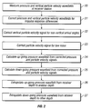
- FIG. 2 is a flowchart illustrating another embodiment of the invention for wavefield extrapolation in dual-sensor towed streamers
- FIG. 3 is a plot of an example time-dependent vertical arrival angle
- FIGS. 4A and 4B are plots of a pressure signal and a vertical particle velocity signal, respectively, corresponding to the arrival angle in FIG. 3 ;
- FIGS. 5A and 5B are plots of up-going and down-going pressure wavefields calculated from the pressure and vertical particle velocity signals shown in FIGS. 4A and 4B , respectively;
- FIG. 6 is a schematic plan view of an extrapolated up-going wavefield with a non-vertical arrival angle
- FIG. 7 is a plot of an extrapolated up-going pressure wavefield constructed according to the method of the invention.
- FIG. 8 is a schematic plan view of an extrapolated down-going wavefield with a non-vertical arrival angle
- FIG. 9 is a plot of an extrapolated down-going pressure wavefield constructed according to the method of the invention.
- FIG. 10 is a flowchart illustrating an embodiment of the invention for constructing extrapolated up-going and down-going pressure wavefields
- FIG. 11 is a flowchart illustrating an embodiment of the invention for constructing an extrapolated up-going pressure wavefield.
- FIG. 12 is a flowchart illustrating an embodiment of the invention for constructing an extrapolated down-going pressure wavefield.
- the method of the invention performs wavefield extrapolation that is accurate for the reflection waves contained in the recorded data and approximately accurate for other seismic events such as multiple reflections.
- FIGS. 1-2 and 10 - 12 show flowcharts illustrating embodiments of the invention for extrapolating wavefields in dual-sensor seismic streamer data at a single receiver station.
- FIG. 1 is a flowchart illustrating a general embodiment of the invention.
- FIG. 2 is a flowchart further illustrating a more particular embodiment of the invention as described in FIG. 1 .
- FIGS. 10-12 are flowcharts illustrating details of the extrapolation process in FIGS. 1-2 .
- FIGS. 3-9 show plots and views that illustrate the embodiments of the invention discussed with reference to the flowcharts in FIGS. 1-2 and 10 - 12 .
- FIG. 1 is a flowchart illustrating an embodiment of the invention for wavefield extrapolation in dual-sensor towed streamers.
- a time-dependent arrival angle is determined at a single receiver station.
- up-going and down-going pressure wavefields are calculated from pressure and vertical particle velocity wavefields measured at the receiver station.
- extrapolated up-going and down-going pressure wavefields are generated from the up-going and down-going pressure wavefields displaced by a time delay based upon the time-dependent arrival angle.
- FIG. 2 is a flowchart illustrating another embodiment of the invention for wavefield extrapolation in dual-sensor towed streamers.
- FIG. 2 illustrates in more detail the portion of the invention discussed in blocks 11 and 12 of FIG. 1 , above.
- a pressure signal h(t) and a vertical particle velocity signal g(t) are recorded at a single receiver station in a dual-sensor towed streamer.
- the pressure signals and vertical particle velocity signals are usually recorded by pressure sensors such as hydrophones and vertical particle velocity sensors such as vertical geophones, respectively.
- the recorded signals will be referred to as pressure signals rather than pressure sensor signals and as particle velocity signals rather than particle velocity sensor signals.
- the other types of seismic sensors could include, but are not limited to, multi-directional particle velocity sensors, particle displacement sensors, particle acceleration sensors, or pressure gradient sensors being used in place of or in addition to vertical particle velocity sensors.
- the pressure and vertical particle velocity sensors may be deployed by themselves, but are more commonly deployed in sensor arrays. Additionally, the pressure sensors and particle velocity sensors are typically positioned together in the streamers, collocated in pairs of the two sensors or in pairs of arrays of the two sensors.
- the method of the invention employs particle motion sensors that are responsive to motions in the particles of the medium to which the motion sensors are coupled, typically water.
- particle motion sensors may be responsive to the displacement of the particles, the velocity of the particles, or the acceleration of the particles in the medium.
- Particle velocity sensors are typically employed and so are used to illustrate the present invention. If motion sensors are used which are -responsive to position, then the position signal is preferably differentiated to convert it to a velocity signal, by computational means well known in the art. If motion sensors are used which are responsive to acceleration (such as accelerometers), then the acceleration signal is preferably integrated to convert it to a velocity signal, by computational means well known in the art.
- the pressure signal, h(t), and the vertical particle velocity signal, g(t), from block 20 are optionally corrected, if deemed necessary, for impulse response differences between the pressure signal sensor and the vertical particle velocity signal sensor, generating a corrected pressure signal, h cor (t), and a corrected vertical particle velocity signal, g cor (t), respectively.
- This correction for relative differences in the instrument transfer functions correspond to instrument impulse responses in the time domain.
- these corrections could be correcting the amplitude and phase of the pressure signals to match the particle velocity signals, or, in an alternative embodiment, correcting the particle velocity signals to match the pressure signals, or, in a further alternative embodiment, correcting both data sets to a common basis. Correcting for relative differences in instrument impulse responses is well known in the art.
- an amplitude scaling equal to the acoustic impedance in the water is preferably applied to the particle velocity signals to correct for the relative differences in amplitudes of pressure and particle velocity. This is also well known in the art.
- the corrected vertical particle velocity signal, g cor is corrected for non-vertical arrival angles of the reflected seismic waves, generating a corrected vertical particle velocity signal, g ang
- Two methods for determining the vertical arrival angle of reflection events at any receiver station of a dual-sensor streamer are described in two co-pending patent applications. One method uses velocity functions for reflections in the survey area, while the other method uses cross-ghosting analyses of the pressure and vertical particle velocity traces recorded at that receiver station. Both of these methods yield the arrival angles as a function of time, ⁇ (t), for a given single receiver station.
- a merged particle velocity signal is generated by merging a recorded vertical particle velocity signal, scaled in an upper frequency range using a time-dependent arrival angle as determined by velocity analysis, with a simulated particle velocity signal, calculated in a lower frequency range from a recorded pressure signal using a time-varying filter based on the time-dependent arrival time.
- Combined pressure and vertical particle velocity signals are generated by combining the recorded pressure and merged particle velocity signals.
- a merged particle velocity signal is generated by combining a recorded vertical particle velocity signal, scaled in an upper frequency range using a time-dependent arrival angle as determined by cross-ghosting analysis, with a simulated particle velocity signal, calculated in a lower frequency range from a recorded pressure signal using a time-varying filter based on the time-dependent arrival angle.
- Combined pressure and vertical particle velocity signals are generated by combining the recorded pressure signal and the merged particle velocity signals.
- FIG. 3 is a plot of an example time-dependent vertical arrival angle 31 .
- the source-to-receiver offset for this actual field trace is approximately 90 meters.
- arrival angle ⁇ (t) 31 has been clipped to a maximum of 60 degrees, and the angles have been quantized to integer values for application of the method described herein.
- FIGS. 4A and 4B are the pressure signal 41 and the vertical particle velocity signal 42 , respectively, corresponding to the arrival angle 31 displayed in FIG. 3 .
- the vertical particle velocity signal 42 is corrected for non-vertical arrival angles.
- the signals are shown for recording times ranging from zero to 200 milliseconds.
- the depth of this receiver station was 22 meters.
- the opposite-polarity ghost 43 on the pressure signal 41 and the same-polarity ghost 44 on the vertical particle velocity signal 42 can be seen, delayed by the vertical ghost reflection delay time of 29.33 milliseconds multiplied by the cosine of 31 degrees (the computed arrival angle for a reflection arriving at 100 milliseconds), yielding a ghost delay time of 25.4 milliseconds.
- the corrected particle velocity signal, g ang from block 22 is optionally corrected for tow noise, if necessary, generating a corrected vertical particle velocity signal, g c .
- the recorded pressure sensor signal having a bandwidth comprising a first frequency range and a second frequency range, the first frequency range being at lower frequencies than the frequencies of the second frequency range, and the recorded particle motion sensor signal having a bandwidth comprising at least the second frequency range.
- the method comprises calculating a particle motion sensor signal in the first frequency range from the recorded pressure sensor signal, thereby generating a simulated particle motion sensor signal in the first frequency range; merging the simulated particle motion sensor signal only in the first frequency range with the recorded particle motion sensor signal in the second frequency range to generate a merged particle motion sensor signal having substantially the same bandwidth as the bandwidth of the recorded pressure sensor signal, and combining the recorded pressure sensor signal and the merged particle motion sensor signal for further processing.
- the trace representing the upward traveling wave field, u(t), and the downward traveling wave field, d(t), are computed from the above traces h(t) and g c (t).
- an up-going pressure wavefield, u(t), is calculated from the corrected pressure signal, h(t), from block 21 and the corrected particle velocity signal, g c (t), from block 23 .
- the up-going pressure wavefield, u(t) is calculated by applying the following equation:
- FIG. 5A is a plot of the up-going pressure wavefield 51 as calculated in Equation (6) from the corrected pressure signal 41 shown in FIG. 4A and the corrected particle velocity signal 42 shown in FIG. 4B .
- a down-going pressure wavefield, d(t) is calculated from the corrected pressure signal, h(t), from block 22 and the corrected particle velocity signal, g c (t), from block 24 .
- the down-going pressure wavefield, d(t) is calculated by applying the following equation:
- FIG. 5B is a plot of the down-going pressure wavefield 52 as calculated in Equation (7) from the corrected pressure signal 41 shown in FIG. 4A and the corrected vertical particle velocity signal 42 shown in FIG. 4B .
- FIG. 6 is a schematic plan view (not to scale) of an extrapolated up-going wavefield with a non-vertical arrival angle.
- FIG. 6 depicts an upward propagating reflection wave front 61 (with upward propagation direction indicated by arrow 62 ) arriving at an angle of ⁇ degrees 63 from vertical 64 .
- the delay time ⁇ is given by:
- ⁇ d c , ( 8 )
- d 66 is the distance traveled by the up-going reflection wave front 61 and c is acoustic wave propagation velocity in the water 65 , which is typically 1500 meters/sec
- ⁇ 63 is defined by:
- FIG. 7 is a plot of an extrapolated up-going pressure wavefield 71 (solid line) constructed according to the method of the invention.
- the upward traveling wave field trace, extrapolated from a depth of 22 meters to one of 15 meters is formed by using, for each time sample, that sample from among the 61 traces that was delayed by the amount of time ⁇ , corresponding most closely to the arrival angle ⁇ (t) shown in FIG. 1 .
- the result is shown in FIG. 7 , along with that up-going pressure wave field 72 (dashed line) prior to extrapolation.
- FIG. 8 is a schematic plan view (not to scale) of an extrapolated down-going wavefield with a non-vertical arrival angle.
- FIG. 8 depicts a downward propagating reflection wave front 81 (with upward propagation direction indicated by arrow 82 ) arriving at an angle of ⁇ degrees 83 from vertical 64 .
- the ghost reflection 81 of the reflection wave front 61 of FIG. 6 would arrive at a receiver positioned at a depth of 15 meters 67 earlier than at one positioned at 22 meters 68 by the same amount of delay time ⁇ given in Equation (11).
- FIG. 9 is a plot of an extrapolated down-going pressure wavefield 91 (solid line) constructed according to the method of the invention. Therefore, the downward traveling wave field trace, d(t), is moved earlier by the same amounts of time as u(t) is delayed, yielding 61 extrapolated, downward traveling wave field traces. And the downward traveling wave field trace, extrapolated from a depth of 22 meters to one of 15 meters is formed by using, for each time sample, that sample from among the 61 traces that was moved earlier by the amount of time ⁇ , corresponding most closely to the arrival angle ⁇ (t) shown in FIG. 1 . That result is shown in FIG. 9 , along with that down-going pressure wave field 92 (dashed line) prior to extrapolation.
- the up-going pressure wavefield, u, from block 24 is extrapolated from the receiver depth, z r , to another depth, z, generating an extrapolated up-going pressure wavefield, u new .
- the down-going pressure wavefield, d, from block 25 is extrapolated from the receiver depth, z r , to the other depth, z, generating an extrapolated down-going pressure wavefield, d new .
- FIG. 10 is a flowchart illustrating an embodiment of the invention for constructing extrapolated up-going and down-going pressure wavefields.
- FIG. 10 illustrates in more detail the portion of the invention discussed in blocks 26 and 27 of FIG. 2 , above.
- a set of arrival angles ⁇ j ⁇ is selected.
- the set of arrival angles ⁇ j ⁇ is selected to cover a range of arrival angles, measured from vertical, expected to be encountered for reflection wavelets in the recorded pressure signals h(t) and vertical particle velocity signals g(t) obtained in block 21 .
- a set of 61 arrival angles ⁇ j are equal to the set ⁇ j
- a set of delay times ⁇ i ⁇ is constructed from the set of arrival angles ⁇ j ⁇ selected in block 100 .
- the set of delay times ⁇ i ⁇ is constructed by applying the following equation, analogous to Equation (11):
- z r receiver depth
- z depth to which the wavefield is extrapolated
- c speed of sound in the medium. In water, c is typically about 1500 m/s.
- ⁇ j ⁇ ⁇ 0°, 1°, 2°, . . . , 60° ⁇ .
- this method would yield 61 up-going wavefield traces.
- a set of up-going pressure wavefields ⁇ u j (t) ⁇ is constructed from the up-going pressure wavefield u(t) from block 22 of FIG. 2 , using the set of time delays ⁇ i ⁇ from block 101 .
- a set of down-going pressure wavefields ⁇ d j (t) ⁇ is constructed from the down-going pressure wavefield d(t) from block 22 of FIG. 2 , using the set of time delays ⁇ i ⁇ from block 31 .
- an extrapolated up-going pressure wavefield u ext (t) is constructed from the set of up-going pressure wavefields ⁇ u j (t) ⁇ from block 102 .
- the extrapolated up-going pressure wavefield u ext (t) extrapolates the up-going pressure wavefield u(t) from the receiver depth z r to u ext (t) at depth z.
- an extrapolated down-going pressure wavefield d ext (t) is constructed from the set of down-going pressure wavefields ⁇ d j (t) ⁇ from block 103 .
- the extrapolated down-going pressure wavefield d ext (t) extrapolates the down-going pressure wavefield d(t) from the receiver depth z r to d ext (t) at depth z.
- FIG. 11 is a flowchart illustrating an embodiment of the invention for constructing an extrapolated up-going pressure wavefield.
- FIG. 11 illustrates in more detail the portion of the invention discussed in block 104 of FIG. 10 , above.
- a time sample is selected in the up-going pressure wavefield u(t) from block 22 of FIG. 2 .
- the time samples are selected in a systematic manner for computational efficiency, but this systematic manner of selection is not a requirement of the invention.
- the time samples are selected sequentially, starting at one end of the seismic trace representing the up-going pressure wavefield u(t) and proceeding to the other end of the trace.
- the arrival angle ⁇ (t) is determined that corresponds to the time sample selected in block 110 .
- the delay time ⁇ i in the set of delay times ⁇ i ⁇ constructed in block 101 of FIG. 10 is determined that corresponds most closely to the arrival angle ⁇ (t) determined in block 111 .
- the up-going pressure wavefield u j (t) in the set of up-going pressure wavefields ⁇ u j (t) ⁇ constructed in block 102 of FIG. 10 is determined that corresponds to the delay time ⁇ i determined in block 112 .
- a time sample corresponding to the time sample selected in block 110 is extracted from the up-going pressure wavefield u j (t) determined in block 113 .
- the time sample extracted from the up-going pressure wavefield u j (t) in block 114 is added to the extrapolated up-going pressure wavefield u ext (t).
- FIG. 12 is a flowchart illustrating an embodiment of the invention for constructing an extrapolated down-going pressure wavefield.
- FIG. 12 illustrates in more detail the portion of the invention discussed in block 105 of FIG. 10 , above.
- a time sample is selected in the down-going pressure wavefield d(t) from block 22 of FIG. 2 .
- the time samples are selected in a systematic manner for computational efficiency, but this systematic manner of selection is not a requirement of the invention.
- the time samples are selected sequentially, starting at one end of the seismic trace representing the down-going pressure wavefield d(t) and proceeding to the other end of the trace.
- the arrival angle ⁇ (t) is determined that corresponds to the time sample selected in block 120 .
- the delay time ⁇ i in the set of delay times ⁇ i ⁇ constructed in block 101 of FIG. 10 is determined that corresponds most closely to the arrival angle ⁇ (t) determined in block 121 .
- the down-going pressure wavefield d j (t) in the set of up-going pressure wavefields ⁇ d j (t) ⁇ constructed in block 102 of FIG. 10 is determined that corresponds to the delay time ⁇ i determined in block 122 .
- a time sample corresponding to the time sample selected in block 120 is extracted from the down-going pressure wavefield d j (t) determined in block 123 .
- the time sample extracted from the down-going pressure wavefield d j (t) in block 124 is added to the extrapolated down-going pressure wavefield d ext (t).
- the invention overcomes spatial aliasing and receiver depth problems by providing a method that performs all operations on each corresponding pair of pressure and vertical particle velocity traces recorded at each streamer receiver station.
- the method of the invention does not require modifying the acquisition recording geometry to avoid spatial aliasing.
Landscapes
- Life Sciences & Earth Sciences (AREA)
- Physics & Mathematics (AREA)
- Remote Sensing (AREA)
- Engineering & Computer Science (AREA)
- Geology (AREA)
- Environmental & Geological Engineering (AREA)
- Acoustics & Sound (AREA)
- General Life Sciences & Earth Sciences (AREA)
- General Physics & Mathematics (AREA)
- Geophysics (AREA)
- Oceanography (AREA)
- Geophysics And Detection Of Objects (AREA)
- Radar Systems Or Details Thereof (AREA)
Priority Applications (3)
| Application Number | Priority Date | Filing Date | Title |
|---|---|---|---|
| US12/313,317 US7929373B2 (en) | 2008-11-19 | 2008-11-19 | Method of wavefield extrapolation for single-station, dual-sensor towed streamer signals |
| AU2009230788A AU2009230788B2 (en) | 2008-11-19 | 2009-10-27 | Method of wavefield extrapolation for single-station, dual-sensor towed streamer signals |
| EP09176290.6A EP2189818B1 (fr) | 2008-11-19 | 2009-11-18 | Procédé d'extrapolation de champ d'onde pour signaux de flûte remorquée à double capteur et station unique |
Applications Claiming Priority (1)
| Application Number | Priority Date | Filing Date | Title |
|---|---|---|---|
| US12/313,317 US7929373B2 (en) | 2008-11-19 | 2008-11-19 | Method of wavefield extrapolation for single-station, dual-sensor towed streamer signals |
Publications (2)
| Publication Number | Publication Date |
|---|---|
| US20100124149A1 US20100124149A1 (en) | 2010-05-20 |
| US7929373B2 true US7929373B2 (en) | 2011-04-19 |
Family
ID=41786360
Family Applications (1)
| Application Number | Title | Priority Date | Filing Date |
|---|---|---|---|
| US12/313,317 Expired - Fee Related US7929373B2 (en) | 2008-11-19 | 2008-11-19 | Method of wavefield extrapolation for single-station, dual-sensor towed streamer signals |
Country Status (3)
| Country | Link |
|---|---|
| US (1) | US7929373B2 (fr) |
| EP (1) | EP2189818B1 (fr) |
| AU (1) | AU2009230788B2 (fr) |
Cited By (5)
| Publication number | Priority date | Publication date | Assignee | Title |
|---|---|---|---|---|
| US9322944B2 (en) | 2013-03-15 | 2016-04-26 | Pgs Geophysical As | Wavefield regularization by 3-D wavefield decomposition for geophysical data |
| US9784869B2 (en) | 2013-05-15 | 2017-10-10 | Pgs Geophysical As | Noise models by selection of transform coefficients |
| US9964656B2 (en) | 2014-08-29 | 2018-05-08 | Pgs Geophysical As | Methods and systems to remove particle-motion-sensor noise from vertical-velocity data |
| US10444386B2 (en) | 2014-08-29 | 2019-10-15 | Pgs Geophysical As | Methods and systems that determine a velocity wavefield from a measured pressure wavefield |
| US11892583B2 (en) * | 2019-07-10 | 2024-02-06 | Abu Dhabi National Oil Company | Onshore separated wave-field imaging |
Families Citing this family (13)
| Publication number | Priority date | Publication date | Assignee | Title |
|---|---|---|---|---|
| US9110191B2 (en) * | 2009-03-30 | 2015-08-18 | Westerngeco L.L.C. | Multiple attenuation for ocean-bottom seismic data |
| WO2011091252A2 (fr) * | 2010-01-22 | 2011-07-28 | Ion Geophysical Corporation | Système séismique doté d'un pouvoir de rejet de mouvements et de réflexions fantômes |
| RU2562711C2 (ru) | 2010-09-02 | 2015-09-10 | Ион Геофизикал Корпорейшн | Многокомпонентный датчик акустических волн и способы |
| US20130329520A1 (en) * | 2012-06-11 | 2013-12-12 | Pgs Geophysical As | Surface-Related Multiple Elimination For Depth-Varying Streamer |
| ITMI20122197A1 (it) * | 2012-12-20 | 2014-06-21 | Eni Spa | Metodo e sistema di monitoraggio continuo da remoto dell'integrita' di condotte in pressione e delle proprieta' dei fluidi trasportati |
| US9696445B2 (en) * | 2013-03-14 | 2017-07-04 | Pgs Geophysical As | Systems and methods for frequency-domain filtering and space-time domain discrimination of seismic data |
| EP2962131A2 (fr) | 2013-03-14 | 2016-01-06 | ION Geophysical Corporation | Dispositifs, systèmes et procédés de détection sismique comprenant un filtrage de bruit |
| US10520623B2 (en) * | 2013-05-31 | 2019-12-31 | Westerngeco L.L.C. | Methods and systems for marine survey acquisition |
| US9678235B2 (en) * | 2013-07-01 | 2017-06-13 | Pgs Geophysical As | Variable depth multicomponent sensor streamer |
| US10557749B2 (en) * | 2016-10-19 | 2020-02-11 | Pgs Geophysical As | Isolating a portion of electric potentials generated by a hydrophone indicative of particle motion or pressure |
| CN106547023B (zh) * | 2017-01-16 | 2017-11-28 | 青岛海洋地质研究所 | 一种精度高、计算稳定的复杂介质地震波场延拓方法 |
| CN108828659B (zh) * | 2018-07-12 | 2020-02-14 | 中国石油天然气集团有限公司 | 基于傅里叶有限差分低秩分解的地震波场延拓方法及装置 |
| CN113093280B (zh) * | 2021-04-07 | 2022-03-29 | 青岛海洋地质研究所 | 基于相干函数控制的虚反射走时电缆等浮校正方法 |
Citations (2)
| Publication number | Priority date | Publication date | Assignee | Title |
|---|---|---|---|---|
| US7359283B2 (en) | 2004-03-03 | 2008-04-15 | Pgs Americas, Inc. | System for combining signals of pressure sensors and particle motion sensors in marine seismic streamers |
| US7616523B1 (en) * | 2008-10-22 | 2009-11-10 | Pgs Geophysical As | Method for combining pressure and motion seismic signals from streamers where sensors are not at a common depth |
Family Cites Families (3)
| Publication number | Priority date | Publication date | Assignee | Title |
|---|---|---|---|---|
| US4648080A (en) * | 1984-06-15 | 1987-03-03 | Western Geophysical Company | Method for determining the far field signature of a marine seismic source from near-field measurements |
| US7336561B2 (en) | 2004-09-07 | 2008-02-26 | Pgs Americas, Inc. | System for attenuation of water bottom multiples in seismic data recorded by pressure sensors and particle motion sensors |
| US7835225B2 (en) * | 2006-10-11 | 2010-11-16 | Pgs Geophysical As | Method for attenuating particle motion sensor noise in dual sensor towed marine seismic streamers |
-
2008
- 2008-11-19 US US12/313,317 patent/US7929373B2/en not_active Expired - Fee Related
-
2009
- 2009-10-27 AU AU2009230788A patent/AU2009230788B2/en not_active Ceased
- 2009-11-18 EP EP09176290.6A patent/EP2189818B1/fr active Active
Patent Citations (3)
| Publication number | Priority date | Publication date | Assignee | Title |
|---|---|---|---|---|
| US7359283B2 (en) | 2004-03-03 | 2008-04-15 | Pgs Americas, Inc. | System for combining signals of pressure sensors and particle motion sensors in marine seismic streamers |
| US20080192571A1 (en) | 2004-03-03 | 2008-08-14 | Svein Torleif Vaage | System for combining signals of pressure sensors and particle motion sensors in marine seismic streamers |
| US7616523B1 (en) * | 2008-10-22 | 2009-11-10 | Pgs Geophysical As | Method for combining pressure and motion seismic signals from streamers where sensors are not at a common depth |
Non-Patent Citations (1)
| Title |
|---|
| Lasse Amundsen, "Wavenumber-based filtering of marine point-source data", Geophysics, vol. 58, No. 9, Sep. 1993, p. 1335-1348. |
Cited By (5)
| Publication number | Priority date | Publication date | Assignee | Title |
|---|---|---|---|---|
| US9322944B2 (en) | 2013-03-15 | 2016-04-26 | Pgs Geophysical As | Wavefield regularization by 3-D wavefield decomposition for geophysical data |
| US9784869B2 (en) | 2013-05-15 | 2017-10-10 | Pgs Geophysical As | Noise models by selection of transform coefficients |
| US9964656B2 (en) | 2014-08-29 | 2018-05-08 | Pgs Geophysical As | Methods and systems to remove particle-motion-sensor noise from vertical-velocity data |
| US10444386B2 (en) | 2014-08-29 | 2019-10-15 | Pgs Geophysical As | Methods and systems that determine a velocity wavefield from a measured pressure wavefield |
| US11892583B2 (en) * | 2019-07-10 | 2024-02-06 | Abu Dhabi National Oil Company | Onshore separated wave-field imaging |
Also Published As
| Publication number | Publication date |
|---|---|
| AU2009230788B2 (en) | 2015-12-10 |
| US20100124149A1 (en) | 2010-05-20 |
| EP2189818A2 (fr) | 2010-05-26 |
| AU2009230788A1 (en) | 2010-06-03 |
| EP2189818A3 (fr) | 2011-07-06 |
| EP2189818B1 (fr) | 2020-01-22 |
Similar Documents
| Publication | Publication Date | Title |
|---|---|---|
| US7929373B2 (en) | Method of wavefield extrapolation for single-station, dual-sensor towed streamer signals | |
| US10989825B2 (en) | Method and system for determining source signatures after source ghost removal | |
| US7872942B2 (en) | Method for imaging a sea-surface reflector from towed dual-sensor streamer data | |
| US8174926B2 (en) | Method for wavefield separation for dual-sensor data using kirchhoff-type datuming and migration | |
| US7986586B2 (en) | Method for deghosting marine seismic streamer data with irregular receiver positions | |
| US8239135B2 (en) | Method for calculation of seismic attributes from seismic signals | |
| US8089825B2 (en) | Method of summing dual-sensor towed streamer signals using cross-ghosting analysis | |
| US8811113B2 (en) | Method of summing dual-sensor towed streamer signals using seismic reflection velocities | |
| US9310503B2 (en) | Methods to process seismic data contaminated by coherent energy radiated from more than one source | |
| AU2012201454B2 (en) | Method for eliminating spectral constraints of acquisition system and earth filtering effects |
Legal Events
| Date | Code | Title | Description |
|---|---|---|---|
| AS | Assignment |
Owner name: PGS GEOPHYSICAL AS,NORWAY Free format text: ASSIGNMENT OF ASSIGNORS INTEREST;ASSIGNOR:BARR, FREDERICK JAMES, JR.;REEL/FRAME:021922/0901 Effective date: 20081119 Owner name: PGS GEOPHYSICAL AS, NORWAY Free format text: ASSIGNMENT OF ASSIGNORS INTEREST;ASSIGNOR:BARR, FREDERICK JAMES, JR.;REEL/FRAME:021922/0901 Effective date: 20081119 |
|
| STCF | Information on status: patent grant |
Free format text: PATENTED CASE |
|
| FPAY | Fee payment |
Year of fee payment: 4 |
|
| MAFP | Maintenance fee payment |
Free format text: PAYMENT OF MAINTENANCE FEE, 8TH YEAR, LARGE ENTITY (ORIGINAL EVENT CODE: M1552); ENTITY STATUS OF PATENT OWNER: LARGE ENTITY Year of fee payment: 8 |
|
| FEPP | Fee payment procedure |
Free format text: MAINTENANCE FEE REMINDER MAILED (ORIGINAL EVENT CODE: REM.); ENTITY STATUS OF PATENT OWNER: LARGE ENTITY |
|
| LAPS | Lapse for failure to pay maintenance fees |
Free format text: PATENT EXPIRED FOR FAILURE TO PAY MAINTENANCE FEES (ORIGINAL EVENT CODE: EXP.); ENTITY STATUS OF PATENT OWNER: LARGE ENTITY |
|
| STCH | Information on status: patent discontinuation |
Free format text: PATENT EXPIRED DUE TO NONPAYMENT OF MAINTENANCE FEES UNDER 37 CFR 1.362 |
|
| FP | Lapsed due to failure to pay maintenance fee |
Effective date: 20230419 |