US7927018B2 - Wheel bearing arrangement comprising an encoder - Google Patents
Wheel bearing arrangement comprising an encoder Download PDFInfo
- Publication number
- US7927018B2 US7927018B2 US11/908,886 US90888606A US7927018B2 US 7927018 B2 US7927018 B2 US 7927018B2 US 90888606 A US90888606 A US 90888606A US 7927018 B2 US7927018 B2 US 7927018B2
- Authority
- US
- United States
- Prior art keywords
- encoder
- wheel bearing
- bearing arrangement
- sealing lip
- inner part
- Prior art date
- Legal status (The legal status is an assumption and is not a legal conclusion. Google has not performed a legal analysis and makes no representation as to the accuracy of the status listed.)
- Active, expires
Links
Images


Classifications
-
- F—MECHANICAL ENGINEERING; LIGHTING; HEATING; WEAPONS; BLASTING
- F16—ENGINEERING ELEMENTS AND UNITS; GENERAL MEASURES FOR PRODUCING AND MAINTAINING EFFECTIVE FUNCTIONING OF MACHINES OR INSTALLATIONS; THERMAL INSULATION IN GENERAL
- F16C—SHAFTS; FLEXIBLE SHAFTS; ELEMENTS OR CRANKSHAFT MECHANISMS; ROTARY BODIES OTHER THAN GEARING ELEMENTS; BEARINGS
- F16C33/00—Parts of bearings; Special methods for making bearings or parts thereof
- F16C33/72—Sealings
- F16C33/76—Sealings of ball or roller bearings
- F16C33/78—Sealings of ball or roller bearings with a diaphragm, disc, or ring, with or without resilient members
- F16C33/7869—Sealings of ball or roller bearings with a diaphragm, disc, or ring, with or without resilient members mounted with a cylindrical portion to the inner surface of the outer race and having a radial portion extending inward
- F16C33/7879—Sealings of ball or roller bearings with a diaphragm, disc, or ring, with or without resilient members mounted with a cylindrical portion to the inner surface of the outer race and having a radial portion extending inward with a further sealing ring
-
- F—MECHANICAL ENGINEERING; LIGHTING; HEATING; WEAPONS; BLASTING
- F16—ENGINEERING ELEMENTS AND UNITS; GENERAL MEASURES FOR PRODUCING AND MAINTAINING EFFECTIVE FUNCTIONING OF MACHINES OR INSTALLATIONS; THERMAL INSULATION IN GENERAL
- F16C—SHAFTS; FLEXIBLE SHAFTS; ELEMENTS OR CRANKSHAFT MECHANISMS; ROTARY BODIES OTHER THAN GEARING ELEMENTS; BEARINGS
- F16C41/00—Other accessories, e.g. devices integrated in the bearing not relating to the bearing function as such
- F16C41/007—Encoders, e.g. parts with a plurality of alternating magnetic poles
-
- F—MECHANICAL ENGINEERING; LIGHTING; HEATING; WEAPONS; BLASTING
- F16—ENGINEERING ELEMENTS AND UNITS; GENERAL MEASURES FOR PRODUCING AND MAINTAINING EFFECTIVE FUNCTIONING OF MACHINES OR INSTALLATIONS; THERMAL INSULATION IN GENERAL
- F16J—PISTONS; CYLINDERS; SEALINGS
- F16J15/00—Sealings
- F16J15/16—Sealings between relatively-moving surfaces
- F16J15/32—Sealings between relatively-moving surfaces with elastic sealings, e.g. O-rings
- F16J15/3248—Sealings between relatively-moving surfaces with elastic sealings, e.g. O-rings provided with casings or supports
- F16J15/3252—Sealings between relatively-moving surfaces with elastic sealings, e.g. O-rings provided with casings or supports with rigid casings or supports
- F16J15/3256—Sealings between relatively-moving surfaces with elastic sealings, e.g. O-rings provided with casings or supports with rigid casings or supports comprising two casing or support elements, one attached to each surface, e.g. cartridge or cassette seals
- F16J15/326—Sealings between relatively-moving surfaces with elastic sealings, e.g. O-rings provided with casings or supports with rigid casings or supports comprising two casing or support elements, one attached to each surface, e.g. cartridge or cassette seals with means for detecting or measuring relative rotation of the two elements
-
- G—PHYSICS
- G01—MEASURING; TESTING
- G01P—MEASURING LINEAR OR ANGULAR SPEED, ACCELERATION, DECELERATION, OR SHOCK; INDICATING PRESENCE, ABSENCE, OR DIRECTION, OF MOVEMENT
- G01P3/00—Measuring linear or angular speed; Measuring differences of linear or angular speeds
- G01P3/42—Devices characterised by the use of electric or magnetic means
- G01P3/44—Devices characterised by the use of electric or magnetic means for measuring angular speed
- G01P3/443—Devices characterised by the use of electric or magnetic means for measuring angular speed mounted in bearings
-
- G—PHYSICS
- G01—MEASURING; TESTING
- G01P—MEASURING LINEAR OR ANGULAR SPEED, ACCELERATION, DECELERATION, OR SHOCK; INDICATING PRESENCE, ABSENCE, OR DIRECTION, OF MOVEMENT
- G01P3/00—Measuring linear or angular speed; Measuring differences of linear or angular speeds
- G01P3/42—Devices characterised by the use of electric or magnetic means
- G01P3/44—Devices characterised by the use of electric or magnetic means for measuring angular speed
- G01P3/48—Devices characterised by the use of electric or magnetic means for measuring angular speed by measuring frequency of generated current or voltage
- G01P3/481—Devices characterised by the use of electric or magnetic means for measuring angular speed by measuring frequency of generated current or voltage of pulse signals
- G01P3/487—Devices characterised by the use of electric or magnetic means for measuring angular speed by measuring frequency of generated current or voltage of pulse signals delivered by rotating magnets
-
- F—MECHANICAL ENGINEERING; LIGHTING; HEATING; WEAPONS; BLASTING
- F16—ENGINEERING ELEMENTS AND UNITS; GENERAL MEASURES FOR PRODUCING AND MAINTAINING EFFECTIVE FUNCTIONING OF MACHINES OR INSTALLATIONS; THERMAL INSULATION IN GENERAL
- F16C—SHAFTS; FLEXIBLE SHAFTS; ELEMENTS OR CRANKSHAFT MECHANISMS; ROTARY BODIES OTHER THAN GEARING ELEMENTS; BEARINGS
- F16C19/00—Bearings with rolling contact, for exclusively rotary movement
- F16C19/02—Bearings with rolling contact, for exclusively rotary movement with bearing balls essentially of the same size in one or more circular rows
- F16C19/04—Bearings with rolling contact, for exclusively rotary movement with bearing balls essentially of the same size in one or more circular rows for radial load mainly
- F16C19/06—Bearings with rolling contact, for exclusively rotary movement with bearing balls essentially of the same size in one or more circular rows for radial load mainly with a single row or balls
-
- F—MECHANICAL ENGINEERING; LIGHTING; HEATING; WEAPONS; BLASTING
- F16—ENGINEERING ELEMENTS AND UNITS; GENERAL MEASURES FOR PRODUCING AND MAINTAINING EFFECTIVE FUNCTIONING OF MACHINES OR INSTALLATIONS; THERMAL INSULATION IN GENERAL
- F16C—SHAFTS; FLEXIBLE SHAFTS; ELEMENTS OR CRANKSHAFT MECHANISMS; ROTARY BODIES OTHER THAN GEARING ELEMENTS; BEARINGS
- F16C2326/00—Articles relating to transporting
- F16C2326/01—Parts of vehicles in general
- F16C2326/02—Wheel hubs or castors
Definitions
- the encoder is fixed to a sheet metal plate which is generally angular.
- the encoder is formed by an elastomer body which is, for example, bonded onto the sheet metal plate by vulcanization.
- the elastomer of the encoder has magnetizeable particles dispersed through it. This magnetizeable structure is magnetized to the finished encoder with alternating polarization.
- the encoder has an annular section about the rotational axis which is alternately encoded in certain sections with north and south polarization.
- the annular section is divided into individual sections which are adjacent to one another at the circumference, each of which sections has a different polarization from the adjacent section.
- the sensor is oriented axially in such a way that the signals can be read by a sensor from an axial direction which is directed in the same way as the rotational axis.
- the reading part of the sensor accordingly lies axially opposite the encoder.
- the present invention relates to a wheel bearing arrangement in which an encoder is arranged in a radial annular space between an inner part and an outer part.
- the quality with which the signals are read by the signals of the encoder depends on the quality of the distance of the sensor from the encoder. The smaller the possible tolerances of the distance, the better the quality of the signals. Particles of dirt in the gap, in particular magnetizeable or magnetic particles of dirt, falsify the reading result.
- the object of the invention is to provide a simple and cost-effective wheel bearing arrangement with which the above-mentioned disadvantages are avoided.
- the wheel bearing arrangement has the features described below:
- the encoder is thus arranged in the radial interior of the wheel bearing and is covered axially by the protective ring.
- the protective ring closes off the bearing interior from the outside.
- the wheel bearing gives a viewer a better impression, in particular if the appearance of the protective ring is intentionally improved through design features, coatings or corresponding coloring. Such design features are advantageous, for example, in the case of wheel bearing arrangements for motorcycles.
- the protective ring is preferably a ring made of sheet metal which is of an L-shaped configuration in longitudinal section when viewed along the rotational axis.
- the protective ring is composed of a nonmagnetizeable material, preferably of a stainless steel.
- the sensor is either arranged spaced axially apart from the protective plate or bears directly against the protective plate.
- the housing of the sensor can also bear directly against the protective plate and the actual reading part of the sensor can be spaced apart from the protective plate. It is important, however, in this case that between the sensor and the sensor housing there should be no gap formed which becomes blocked with destructive particles of dirt.
- the encoder is closed off from the outside by the protective ring to prevent soiling. Between the stationary protective ring and the rotationally moveable outer part an annular sealing gap is formed. As an alternative to this, the protective ring is at the same time the carrier of one or more elastic sealing lips which bear against the outer part in a seal-forming fashion.
- the encoder is preferably composed of a plastic or of an elastomer or of some other material which can be magnetically encoded per se or by adding magnetizeable additives.
- the carrier for the encoder is preferably an angular ring made of any suitable material, preferably sheet metal.
- the encoder is preferably bonded onto the carrier, for example by vulcanization.
- the carrier of the encoder is additionally sealed off from the inside or the outside by means of one or more sealing lips which bear in a seal-forming fashion against the inner part or which are spaced apart from the inner part with a sealing gap.
- the sealing lip is either formed separately from the encoder or is formed in one part with the encoder from the preferably elastic material.
- the sealing lip which is composed of the elastic material is provided, like the annular section, with magnetizeable additives, or in contrast to the annular section it is not provided with magnetizeable additives.
- One refinement of the invention provides that in the new state in the wheel bearing arrangement the sealing lip bears with radial prestress in a seal-forming fashion against the inner part or against a limb of the protective ring. After a predictable operating time, the magnetizeable elastic material is then worn in seal-forming contact to such an extent that an optimum, contactless sealing gap with a minimum gap thickness is produced.
- FIG. 1 is a section view of a portion of a wheel bearing arrangement illustrating a portion of the outer part, the inner part, a rolling body and the encoder.
- FIG. 2 is an enlarged front view of a detail taken along direction 2 - 2 of FIG. 1 and illustrates a portion of the encoder.
- FIG. 3 is a section view showing a detail of the annular gap, the encoder and the protective plate.
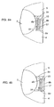
- FIG. 4 a is a section view of a portion of a wheel bearing arrangement illustrating an elastic sealing lip.
- FIG. 4 b is a section view showing a portion of the wheel bearing arrangement with the elastic lip bearing against the inner part.
- FIG. 4 c is a section view illustrating a portion of the wheel bearing arrangement with the elastic lip bearing against a limb of the protective plate and a second sealing lip positioned on the protective plate.
- FIG. 4 d is a section view illustrating a portion of the wheel bearing arrangement with the elastic lip bearing against the inner part and a second sealing lip positioned on the protective plate bearing against the outer part.
- FIG. 4 e is a section view illustrating a portion of the wheel bearing arrangement with a sealing lip positioned on the protective plate and bearing against the outer part.
- FIG. 5 is a section view of a wheel bearing arrangement with a sealing lip positioned at a distal end of the encoder and also showing a second sealing lip positioned on the protective plate.
- FIG. 6 a is a section view of a portion of the wheel bearing arrangement with an annular sealing gap between the encoder and a limb of the protective plate and a sealing lip positioned on the protective plate.
- FIG. 6 b illustrates the wheel bearing arrangement showing FIG. 6 a with the sealing lip positioned on the protective plate bearing against the outer part.
- FIGS. 1 to 6 are all partial illustrations or details of a wheel bearing arrangement and alternative embodiments in the longitudinal section along the rotational axis of the wheel bearing arrangement.
- FIG. 1 shows a wheel bearing arrangement 1 in which an encoder 2 is arranged in a radial annular space 3 between an inner part 4 and an outer part 5 .
- the outer part 5 is an outer ring of a ball bearing illustrated only in a schematically simplified form.
- the inner part 4 is the inner ring of this ball bearing.
- the encoder 2 is seated on a carrier ring 6 in the form of an angular ring.
- the carrier ring 6 is seated with a limb 6 a on the outer part and limb 6 a points away from the rolling bodies 7 of the wheel bearing arrangement 1 or alternatively, as illustrated for example in FIG. 3 , points axially toward them.
- the radially oriented limb is a carrier plate 6 b to which the encoder 2 composed of an annular section 2 a is fixed.
- the encoder 2 has the annular section 2 a .
- the annular section 2 a in FIG. 2 is an enlarged detail of a front view in the direction II-II according to the figure and is not illustrated to scale.
- Sections 2 b with north polarization N are adjacent to sections with south polarization S in the circumferential direction of the encoder 2 .
- the circumferential boundaries 10 , 11 of the annular section bound the readable part of the encoder 2 .
- the encoder 2 is followed in the axial direction by a protective ring 8 in the form of an angular ring made of nonmagnetizeable sheet metal.
- the protective ring 8 is seated fixedly with the axially oriented limb 8 a on the inner part 4 .
- the radially oriented limb is a protective plate 8 b on which a sensor 9 bears. Since the protective plate 8 b cannot be magnetized, it is possible to use the sensor 9 to read the signals of the encoder 2 through the protective ring 8 .
- the inner part 4 , the protective plate 8 b and the sensor 9 are fixed to the vehicle.
- the outer part 5 is rotationally moveable with the encoder 2 .
- a radial annular gap 12 is formed between the protective plate 8 b and the limb 6 a in each of the illustrations according to FIG. 1 , FIG. 4 a and FIG. 4 b .
- An annular gap 13 is formed between the protective plate 8 b and the outer part 5 in the illustration according to FIG. 3 . Otherwise, the annular space 3 is covered axially by the protective plate 8 b .
- FIG. 4 a shows a wheel bearing arrangement according to claim 1 in which the encoder 2 is fixed to the carrier plate 6 b , and also at least one elastic sealing lip 14 is fixed.
- the elastic sealing lip 14 is directed toward the inner part 4 and extends in a seal-forming fashion on the limb 8 a .
- the sealing lip 14 seals the annular space 3 so as to prevent lubrication grease from escaping from the annular space 3 .
- the encoder 2 with the carrier ring 6 can firstly be pressed as a single assembly into the outer part 5 . Owing to the orientation of the sealing lip toward the inside, it is possible subsequently to push the limb 8 a under the sealing lip 14 .
- FIG. 4 b separate mounting is also conceivable.
- sealing lip 14 rests directly on the inner part 4 , and as a result the protective ring 8 can be mounted independently of the carrier ring 6 .
- the sealing lip 14 seals off the annular space 3 so as to prevent the ingress of moisture and dirt from the surroundings of the wheel bearing arrangement 1 by virtue of the orientation of said sealing lip 14 in the arrangement 4 .
- the carrier plate 6 b is provided with a sealing lip 14 and the protective plate 8 b is provided with a sealing lip 15 .
- the sealing lip 15 bears radially against the limb 6 a
- the arrangement according to FIG. 4 d it bears radially directly on the outer part 5 .
- the arrangement according to FIG. 4 d is preferably used as a cartridge arrangement, i.e. it is a premounted unit composed of the carrier ring 6 with encoder 2 and seal 14 and composed of the protective ring 8 with seal 15 between the outer part 5 and the inner part 4 .
- the elastic material of an encoder 17 continues into a sealing element.
- a defined sealing gap 16 is provided between an encoder 17 and the limb 8 a .
- a sealing lip 18 is formed in one piece with the encoder 17 , said sealing lip 18 bearing radially.
- This sealing lip 18 can be provided with the magnetizeable additives. If the sealing lip 18 is provided with the magnetizeable additives, it will have worn selectively after a predetermined operating period in such a way that, as illustrated in FIGS. 6 a, b , an optimum minimum annular sealing gap 19 is formed between the encoder 17 and the limb 8 a .
Abstract
Description
-
- An encoder is arranged in a radial annular space between an inner part and an outer part. The outer part is optionally an outer ring of a wheel bearing or a housing and is preferably connected in a rotationally fixed fashion to a vehicle wheel. At least one raceway for at least one series of rolling bodies is formed at least in the outer ring. The outer part is supported on the inner part by means of rolling bodies and is mounted on the inner part so as to be rotatable about the rotational axis. The inner part is an inner ring of a wheel bearing with at least one raceway or is a bolt or the like on which a vehicle wheel is rotatably mounted.
- The encoder is directed axially away from rolling bodies of the wheel bearing arrangement toward a sensor which is arranged axially behind a rotationally fixed protective plate. The protective plate is rotationally fixed with respect to the inner part.
- The protective plate covers the annular space of the wheel bearing arrangement at least partially in an axial direction with the rolling bodies.
Claims (8)
Priority Applications (1)
| Application Number | Priority Date | Filing Date | Title |
|---|---|---|---|
| US11/908,886 US7927018B2 (en) | 2005-03-18 | 2006-03-09 | Wheel bearing arrangement comprising an encoder |
Applications Claiming Priority (3)
| Application Number | Priority Date | Filing Date | Title |
|---|---|---|---|
| US66335505P | 2005-03-18 | 2005-03-18 | |
| US11/908,886 US7927018B2 (en) | 2005-03-18 | 2006-03-09 | Wheel bearing arrangement comprising an encoder |
| PCT/DE2006/000423 WO2006097072A1 (en) | 2005-03-18 | 2006-03-09 | Wheel bearing arrangement comprising an encoder |
Publications (2)
| Publication Number | Publication Date |
|---|---|
| US20080166079A1 US20080166079A1 (en) | 2008-07-10 |
| US7927018B2 true US7927018B2 (en) | 2011-04-19 |
Family
ID=36588800
Family Applications (1)
| Application Number | Title | Priority Date | Filing Date |
|---|---|---|---|
| US11/908,886 Active 2028-01-31 US7927018B2 (en) | 2005-03-18 | 2006-03-09 | Wheel bearing arrangement comprising an encoder |
Country Status (4)
| Country | Link |
|---|---|
| US (1) | US7927018B2 (en) |
| JP (1) | JP2008537066A (en) |
| DE (1) | DE112006000366B4 (en) |
| WO (1) | WO2006097072A1 (en) |
Cited By (6)
| Publication number | Priority date | Publication date | Assignee | Title |
|---|---|---|---|---|
| US20090174151A1 (en) * | 2006-03-31 | 2009-07-09 | Nok Corporation | Sealing Device |
| US20100189384A1 (en) * | 2007-09-12 | 2010-07-29 | Schaeffler Technologies Gmbh & Co., Kg | Measurement arrangement for a mounted shaft |
| US20130259415A1 (en) * | 2012-03-30 | 2013-10-03 | Keihin Corporation | Rolling bearing with seal |
| US20150345563A1 (en) * | 2012-12-05 | 2015-12-03 | Aktiebolaget Skf | Bearing power generating configuration |
| US20190162312A1 (en) * | 2016-05-24 | 2019-05-30 | Ntn Corporation | Bearing sealing device |
| US20190226584A1 (en) * | 2018-01-19 | 2019-07-25 | American Axle & Manufacturing, Inc. | Lip seal with air-side spring |
Families Citing this family (5)
| Publication number | Priority date | Publication date | Assignee | Title |
|---|---|---|---|---|
| US8237431B2 (en) * | 2007-07-05 | 2012-08-07 | Terry Fruehling | Wheel speed sensor |
| DE102008031665B4 (en) | 2007-07-05 | 2020-06-10 | Harley-Davidson Motor Company Group, LLC | Wheel speed sensor |
| FR2923564B1 (en) * | 2007-11-09 | 2010-04-23 | Roulements Soc Nouvelle | SEALING DEVICE, INCLUDING AN INTEGRATED MAGNETIC ENCODER, COMPRISING A MAGNETIC SEALING LAUNDRY |
| JP5540961B2 (en) * | 2010-07-15 | 2014-07-02 | 日本精機株式会社 | Rotational speed detection device and vehicle speed detection system |
| EP2909492A4 (en) * | 2012-10-19 | 2016-07-06 | Skf Ab | Roller bearing and method for assembling a roller bearing |
Citations (10)
| Publication number | Priority date | Publication date | Assignee | Title |
|---|---|---|---|---|
| US4948277A (en) * | 1989-01-20 | 1990-08-14 | The Torrington Company | Rotating seal with integrated magnetic encoder for a bearing with information sensors |
| US4968156A (en) * | 1989-11-27 | 1990-11-06 | The Torrington Company | Bearing with a magnetic field sensor |
| US5195830A (en) * | 1991-07-05 | 1993-03-23 | Skf France | Leaktight sensor assembly which can be incorporated in a data sensor bearing and bearing equipped with such an assembly |
| US5431413A (en) * | 1993-01-19 | 1995-07-11 | The Torrington Company | Seal incorporating an encoder |
| US5470157A (en) * | 1994-03-29 | 1995-11-28 | The Timken Company | Bearing seal for sensing angular velocity |
| US5969518A (en) * | 1996-10-28 | 1999-10-19 | Fag Automobiltechnik Ag | Antifriction mounting having a rotational-speed measuring device protected from contamination |
| US6045133A (en) * | 1995-02-03 | 2000-04-04 | Firma Carl Freudenberg | Sealing arrangement |
| US6605938B1 (en) * | 1999-06-02 | 2003-08-12 | Koyo Seiko Co., Ltd. | Compact wheel speed detector capable of saving space and improving workability |
| US6637754B1 (en) | 1999-11-17 | 2003-10-28 | Ntn Corporation | Wheel bearing and sealing device therefor |
| US6994472B2 (en) * | 2002-12-24 | 2006-02-07 | Koyo Seiko Co., Ltd. | Rolling bearing apparatus |
Family Cites Families (4)
| Publication number | Priority date | Publication date | Assignee | Title |
|---|---|---|---|---|
| FR2642483B1 (en) * | 1989-01-20 | 1991-04-05 | Roulements Soc Nouvelle | ROTATING SEAL WITH INTEGRATED MAGNETIC ENCODER, PARTICULARLY FOR BEARINGS WITH INFORMATION SENSORS |
| JPH03279061A (en) * | 1990-03-29 | 1991-12-10 | Ntn Corp | Wheel rotating speed detecting device |
| FR2698421B1 (en) * | 1992-11-24 | 1995-06-02 | Skf France | Housing for radial fixing of a bearing. |
| FR2730566B1 (en) * | 1995-02-09 | 1997-06-13 | Skf France | ENCODER DEVICE FOR ROTATION SPEED SENSOR AND BEARING PROVIDED WITH SUCH A DEVICE |
-
2006
- 2006-03-09 JP JP2008504609A patent/JP2008537066A/en active Pending
- 2006-03-09 US US11/908,886 patent/US7927018B2/en active Active
- 2006-03-09 WO PCT/DE2006/000423 patent/WO2006097072A1/en not_active Application Discontinuation
- 2006-03-09 DE DE112006000366.6T patent/DE112006000366B4/en active Active
Patent Citations (10)
| Publication number | Priority date | Publication date | Assignee | Title |
|---|---|---|---|---|
| US4948277A (en) * | 1989-01-20 | 1990-08-14 | The Torrington Company | Rotating seal with integrated magnetic encoder for a bearing with information sensors |
| US4968156A (en) * | 1989-11-27 | 1990-11-06 | The Torrington Company | Bearing with a magnetic field sensor |
| US5195830A (en) * | 1991-07-05 | 1993-03-23 | Skf France | Leaktight sensor assembly which can be incorporated in a data sensor bearing and bearing equipped with such an assembly |
| US5431413A (en) * | 1993-01-19 | 1995-07-11 | The Torrington Company | Seal incorporating an encoder |
| US5470157A (en) * | 1994-03-29 | 1995-11-28 | The Timken Company | Bearing seal for sensing angular velocity |
| US6045133A (en) * | 1995-02-03 | 2000-04-04 | Firma Carl Freudenberg | Sealing arrangement |
| US5969518A (en) * | 1996-10-28 | 1999-10-19 | Fag Automobiltechnik Ag | Antifriction mounting having a rotational-speed measuring device protected from contamination |
| US6605938B1 (en) * | 1999-06-02 | 2003-08-12 | Koyo Seiko Co., Ltd. | Compact wheel speed detector capable of saving space and improving workability |
| US6637754B1 (en) | 1999-11-17 | 2003-10-28 | Ntn Corporation | Wheel bearing and sealing device therefor |
| US6994472B2 (en) * | 2002-12-24 | 2006-02-07 | Koyo Seiko Co., Ltd. | Rolling bearing apparatus |
Cited By (11)
| Publication number | Priority date | Publication date | Assignee | Title |
|---|---|---|---|---|
| US20090174151A1 (en) * | 2006-03-31 | 2009-07-09 | Nok Corporation | Sealing Device |
| US8087673B2 (en) * | 2006-03-31 | 2012-01-03 | Nok Corporation | Sealing device |
| US8353519B2 (en) | 2006-03-31 | 2013-01-15 | Nok Corporation | Sealing device |
| US20100189384A1 (en) * | 2007-09-12 | 2010-07-29 | Schaeffler Technologies Gmbh & Co., Kg | Measurement arrangement for a mounted shaft |
| US9267960B2 (en) * | 2007-09-12 | 2016-02-23 | Schaeffler Technologies AG & Co. KG | Measurement arrangement for a mounted shaft |
| US20130259415A1 (en) * | 2012-03-30 | 2013-10-03 | Keihin Corporation | Rolling bearing with seal |
| US8876394B2 (en) * | 2012-03-30 | 2014-11-04 | Keihin Corporation | Rolling bearing with seal |
| US20150345563A1 (en) * | 2012-12-05 | 2015-12-03 | Aktiebolaget Skf | Bearing power generating configuration |
| US20190162312A1 (en) * | 2016-05-24 | 2019-05-30 | Ntn Corporation | Bearing sealing device |
| US10648571B2 (en) * | 2016-05-24 | 2020-05-12 | Ntn Corporation | Bearing sealing device |
| US20190226584A1 (en) * | 2018-01-19 | 2019-07-25 | American Axle & Manufacturing, Inc. | Lip seal with air-side spring |
Also Published As
| Publication number | Publication date |
|---|---|
| DE112006000366B4 (en) | 2020-06-18 |
| JP2008537066A (en) | 2008-09-11 |
| DE112006000366A5 (en) | 2007-11-22 |
| US20080166079A1 (en) | 2008-07-10 |
| WO2006097072A1 (en) | 2006-09-21 |
Similar Documents
| Publication | Publication Date | Title |
|---|---|---|
| US7927018B2 (en) | Wheel bearing arrangement comprising an encoder | |
| US6692153B2 (en) | Wheel support bearing assembly | |
| US7350976B2 (en) | Bearing for a wheel of vehicle | |
| US7126328B2 (en) | Rolling bearing unit with rotational speed detecting device | |
| US7872554B2 (en) | Sealing device and rotation detector | |
| US6045133A (en) | Sealing arrangement | |
| US20100296759A1 (en) | Encoder element for displaying an adjustment or movement of a bearing constituent | |
| JP4780314B2 (en) | Pulsar ring for rotary encoder | |
| JP4278324B2 (en) | Wheel bearing | |
| US20100027927A1 (en) | Sensor attaching sealing device and vehicle rolling bearing using the same | |
| JP2001241435A (en) | Rolling bearing unit with encoder for automobile | |
| WO2017159804A1 (en) | Wheel bearing device | |
| JP2004211832A (en) | Bearing device corresponding to sensor | |
| JP4239669B2 (en) | Rolling bearing unit for wheel support | |
| JP2005030547A (en) | Rolling bearing unit with rotational speed detecting device | |
| JP5061652B2 (en) | Magnetized pulsar ring and sensor-equipped rolling bearing device using the same | |
| JP2006064180A (en) | Vehicular rolling bearing unit with encoder | |
| JP4995673B2 (en) | Wheel bearing device with rotation speed detector | |
| JP2006064180A5 (en) | ||
| JP2008267423A (en) | Bearing seal | |
| JP2005140334A (en) | Bearing with magnetic encoder | |
| JP2006153110A (en) | Bearing seal | |
| JP2006133175A (en) | Bearing device for wheel with rotation speed detecting device | |
| JP2006038120A (en) | Cover seal | |
| JP2002147478A (en) | Wheel bearing |
Legal Events
| Date | Code | Title | Description |
|---|---|---|---|
| AS | Assignment |
Owner name: SCHAEFFLER KG, GERMANY Free format text: ASSIGNMENT OF ASSIGNORS INTEREST;ASSIGNORS:HEIM, JENS;HAMILTON, JON;REEL/FRAME:020284/0252;SIGNING DATES FROM 20071030 TO 20071113 Owner name: SCHAEFFLER KG, GERMANY Free format text: ASSIGNMENT OF ASSIGNORS INTEREST;ASSIGNORS:HEIM, JENS;HAMILTON, JON;SIGNING DATES FROM 20071030 TO 20071113;REEL/FRAME:020284/0252 |
|
| STCF | Information on status: patent grant |
Free format text: PATENTED CASE |
|
| FPAY | Fee payment |
Year of fee payment: 4 |
|
| AS | Assignment |
Owner name: SCHAEFFLER TECHNOLOGIES GMBH & CO. KG, GERMANY Free format text: MERGER AND CHANGE OF NAME;ASSIGNORS:SCHAEFFLER KG;SCHAEFFLER VERWALTUNGS DREI KG;REEL/FRAME:037407/0556 Effective date: 20091113 |
|
| AS | Assignment |
Owner name: SCHAEFFLER TECHNOLOGIES AG & CO. KG, GERMANY Free format text: CHANGE OF NAME;ASSIGNOR:SCHAEFFLER TECHNOLOGIES GMBH & CO. KG;REEL/FRAME:037731/0834 Effective date: 20120101 Owner name: SCHAEFFLER TECHNOLOGIES AG & CO. KG, GERMANY Free format text: CHANGE OF NAME;ASSIGNOR:SCHAEFFLER TECHNOLOGIES GMBH & CO. KG;REEL/FRAME:037732/0347 Effective date: 20150101 Owner name: SCHAEFFLER TECHNOLOGIES GMBH & CO. KG, GERMANY Free format text: MERGER AND CHANGE OF NAME;ASSIGNORS:SCHAEFFLER TECHNOLOGIES AG & CO. KG;SCHAEFFLER VERWALTUNGS 5 GMBH;REEL/FRAME:037732/0228 Effective date: 20131231 |
|
| AS | Assignment |
Owner name: SCHAEFFLER TECHNOLOGIES AG & CO. KG, GERMANY Free format text: CORRECTIVE ASSIGNMENT TO CORRECT THE PROPERTY NUMBERS PREVIOUSLY RECORDED ON REEL 037732 FRAME 0347. ASSIGNOR(S) HEREBY CONFIRMS THE APP. NO. 14/553248 SHOULD BE APP. NO. 14/553258;ASSIGNOR:SCHAEFFLER TECHNOLOGIES GMBH & CO. KG;REEL/FRAME:040404/0530 Effective date: 20150101 |
|
| MAFP | Maintenance fee payment |
Free format text: PAYMENT OF MAINTENANCE FEE, 8TH YEAR, LARGE ENTITY (ORIGINAL EVENT CODE: M1552); ENTITY STATUS OF PATENT OWNER: LARGE ENTITY Year of fee payment: 8 |
|
| MAFP | Maintenance fee payment |
Free format text: PAYMENT OF MAINTENANCE FEE, 12TH YEAR, LARGE ENTITY (ORIGINAL EVENT CODE: M1553); ENTITY STATUS OF PATENT OWNER: LARGE ENTITY Year of fee payment: 12 |