US7903518B2 - Optical recording method and optical recording device - Google Patents
Optical recording method and optical recording device Download PDFInfo
- Publication number
- US7903518B2 US7903518B2 US11/587,697 US58769706A US7903518B2 US 7903518 B2 US7903518 B2 US 7903518B2 US 58769706 A US58769706 A US 58769706A US 7903518 B2 US7903518 B2 US 7903518B2
- Authority
- US
- United States
- Prior art keywords
- recording
- write strategy
- pulse width
- recommended
- optical
- Prior art date
- Legal status (The legal status is an assumption and is not a legal conclusion. Google has not performed a legal analysis and makes no representation as to the accuracy of the status listed.)
- Expired - Fee Related, expires
Links
Images


Classifications
-
- G—PHYSICS
- G11—INFORMATION STORAGE
- G11B—INFORMATION STORAGE BASED ON RELATIVE MOVEMENT BETWEEN RECORD CARRIER AND TRANSDUCER
- G11B7/00—Recording or reproducing by optical means, e.g. recording using a thermal beam of optical radiation by modifying optical properties or the physical structure, reproducing using an optical beam at lower power by sensing optical properties; Record carriers therefor
- G11B7/004—Recording, reproducing or erasing methods; Read, write or erase circuits therefor
- G11B7/0045—Recording
- G11B7/00456—Recording strategies, e.g. pulse sequences
Definitions
- the present invention relates to an optical recording method and an optical recording device for recording information on an optical recording medium, more particularly to a method of determining the write strategy to use in recording.
- One example of a conventional optical recording device is a device having a recording and reproducing unit with a strategy section that controls the write strategy for writing to an optical disk, and a strategy information recording unit in which strategy information for operating the strategy section is recorded; strategy information corresponding to device information about the recording device and medium information about the optical disk is recorded in the strategy information recording section, read from the strategy information recording section, and transferred together with the medium information to the recording device.
- Default strategy information is also recorded in the strategy recording section in this device; if strategy information corresponding to the device information and medium information transferred from the recording device is not recorded on the storage information recording section, the default strategy information is read and transferred to the recording device (see, for example, Patent Document 1).
- Patent Document 1 Japanese Patent Application Publication No. 2002-56531 (pp. 1-9, FIGS. 1-15)
- the present invention addresses the above problems, a first object being to obtain an optical recording method and optical recording device that do not require the storage of all strategy information suitable for every optical disk and thus do not require storage devices of large capacity.
- a second object is to obtain an optical recording method and optical recording device with which appropriate recording can be carried out even on an optical disk for which the optimal strategy information has not been determined in advance.
- the present invention provides an optical recording method comprising the steps of:
- an appropriate write strategy responsive to the characteristics of the optical system of the optical pickup of the optical recording device used in recording can be determined, and recording can be carried out using the optimal write strategy.
- a further effect is that it is not necessary to determine the appropriate write strategy for all optical recording media experimentally beforehand, so labor and cost can be saved, and a large-capacity memory is not required.
- FIG. 1 is a block diagram showing an optical recording device in a first embodiment of this invention.
- FIGS. 2 ( a ) to 2 ( c ) shows examples of asymmetry values of the reproduced signal detected in the asymmetry detector in the first embodiment of this invention.
- FIG. 3 shows examples of write strategies generated in the optical recording device in the first embodiment of this invention when the optical disk is a medium of the dye type.
- FIG. 4 is a flowchart illustrating the recording procedure in the optical recording device in a first embodiment of this invention.
- FIG. 5 is a flowchart for calculating the write strategy from recommended write strategy parameters recorded on an optical disk in the optical recording device in the first embodiment of this invention.
- FIG. 6 illustrates the relationship between a pulse width 2TF and a recommended write strategy parameter 2TP in the optical recording device in the first embodiment of this invention.
- FIG. 7 illustrates the relationship between a pulse width LTF and a recommended write strategy parameter LTP in the optical recording device in the first embodiment of this invention.
- FIG. 8 illustrates the relationship between pulse widths 1TF and 2TF in the write strategy in the optical recording device in the first embodiment of this invention.
- FIG. 9 illustrates the relationship between pulse widths 1TF and 3TF in the write strategy in the optical recording device in the first embodiment of this invention.
- FIG. 10 illustrates the relationship between the pulse width TM and the recommended write strategy value TMP ⁇ 2TP ⁇ LTP/1TP in the optical recording device in the first embodiment.
- FIG. 11 illustrates the relationship between an asymmetry value ⁇ 1 recorded on the optical disk and an asymmetry value ⁇ 2 used in recording in the first embodiment of this invention.
- FIG. 12 illustrates the relationship between jitter value and the write strategy used in recording in the optical recording device in the first embodiment of this invention.
- FIG. 13 is a block diagram showing an optical recording device in a second embodiment of this invention.
- FIGS. 14 ( a ) and 14 ( b ) shows examples of modulation degrees of the reproduced signal detected in the modulation degree detector in the second embodiment of this invention.
- FIG. 15 shows examples of write strategies generated in the optical recording device in second and third embodiments of this invention when the optical disk is a medium of the phase change type.
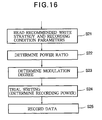
- FIG. 16 is a flowchart illustrating the recording procedure in the optical recording device in the second and third embodiments of this invention.
- FIG. 17 illustrates the relationship between the recommended write strategy value PW1 ⁇ P1 ⁇ TMP1 and the power ratio ⁇ 1 in the optical recording device in the second embodiment of this invention.
- FIG. 18 illustrates the relationship between the recommended write strategy value TMP1 ⁇ TCP1/1TP1 and the modulation degree MOD 1 used for recording in the optical recording device in the second embodiment.
- FIG. 19 illustrates the relationship between jitter value and the power ratio used in recording in the optical recording device in the second embodiment of this invention.
- FIG. 20 illustrates the relationship between the recommended recording condition value (PW2 ⁇ P2)/1TP1 recorded on the optical disk and the power ratio ⁇ 2 in the optical recording device in the third embodiment.
- FIG. 21 illustrates the relationship between the recommended recording condition value 1TP2 ⁇ PW2 recorded on the optical disk and the modulation degree MOD 2 used in recording in the optical recording device in the third embodiment of this invention.
- FIG. 22 illustrates the relationship between jitter value and the power ratio used in recording in the optical recording device in the third embodiment of this invention.
- 100 optical recording device 110 semiconductor laser, 120 laser driver, 130 collimator lens, 140 beam splitter, 150 objective lens, 160 optical disk, 170 sensor lens, 180 photodetector, 190 head amplifier, 200 data decoder, 210 pre-pit detector, 220 asymmetry detector, 230 data encoder, 240 laser waveform controller, 250 central controller, 260 modulation degree detector
- the recording method and recording device in the present invention record information on an optical disk on which recommended write strategy parameters or recommended recording conditions have been prerecorded.
- the recommended write strategy parameters or recommended recording conditions represent a write strategy or recommended recording conditions suitable for use in recording on the optical disk, and are recorded in the form of pre-pits, for example, in a predetermined area on the optical disk: the lead-in area, for example.
- the optical disk includes, for example, a groove part (not shown) comprising grooves in which information is recorded, and a land part (not shown) between the grooves; the recommended write strategy parameters (including the recommended recording power) set by the recording media manufacturer are recorded in the land part together with other information such as an asymmetry value.
- the recommended write strategy parameters envision that that recording will be performed under predefined conditions. For different recording conditions, therefore, it is preferable to use a write strategy different from the recommended write strategy parameters.
- a write strategy is determined based on the recommended write strategy parameters or recommended recording conditions read from the optical disk, and on the characteristics of the optical system of the optical pickup of the optical recording device used in recording, and recording is performed by use of the write strategy thus determined.
- the optical recording method in the embodiments below performs mark-edge recording (PWM recording). To record information, it causes a semiconductor laser to emit multiple pulses to form recording marks, based on the data to be recorded on the optical disk.
- the write strategy used in the following embodiments is a strategy of the multi-pulse type, having one or more pulses in the mark period.
- the pulse widths are changed responsive to the characteristics of the optical system of the optical pickup of the optical recording device.
- the recording of information onto the optical disk is carried out by illuminating the optical disk with optical pulses in patterns corresponding to the 3T to 11T and 14T marks (T being the channel clock period) in EFM modulation.
- the longest mark (the mark with length 14T) is a sync pattern.
- FIG. 1 shows an example of the basic structure of an optical recording device 100 according to the first embodiment of the invention.
- the semiconductor laser 110 used as a laser light source is driven and controlled by a laser driver 120 .
- a laser beam emitted from the semiconductor laser 110 with the output value (reproducing power) necessary for data reproduction is focused onto the optical disk 160 through a collimator lens 130 , beam splitter 140 , and objective lens 150 .
- the light reflected from the optical disk 160 passes through the objective lens 150 , is separated from the incident light by the beam splitter 140 , and is then received through a sensor lens 170 by a photodetector 180 .
- the semiconductor laser 110 , collimator lens 130 , beam splitter 140 , objective lens 150 , and sensor lens 170 constitute the optical system, which in turn, together with the photodetector 180 , constitutes the optical pickup.
- the photodetector 180 converts the optical signal to an electric signal.
- the electric signal converted by the photodetector 180 is input through a head amplifier 190 into a data decoder 200 , a pre-pit detector 210 , and an asymmetry detector 220 .
- the data decoder 200 generates (reproduces) the data recorded on the optical disk 160 by performing such processes as demodulation and error correction on the input electric signal.
- the pre-pit detector 210 detects pre-pit information including such information as the recommended write strategy parameters, which are the recommended parameters of the write strategy to be used for recording on the optical disk 160 .
- the peak level A 1 and bottom level A 2 occur in places where spaces of maximum length alternate with marks of maximum length; these values are expressed with a zero level equal to the average value of the peak level and bottom level in places where spaces of minimum length and marks of minimum length appear alternately.
- FIGS. 2 ( a ) to ( c ) show examples of the detection of the asymmetry value in the detected reproduced signal in the asymmetry detector 220 .
- FIG. 2 ( a ) illustrates the case in which ⁇ 0.
- FIG. 2 ( c ) illustrates the case in which ⁇ >0.
- a data encoder 230 adds error correction symbols to the original data to be recorded and modulates the data to generate the recording data on which the driving signal to the semiconductor laser 110 is based.
- a laser waveform controller 240 generates a write strategy signal based on the recording data.
- the laser waveform controller 240 When provided with recording data specifying one of 3T to 11T or 14T by a central controller 250 , that is, the laser waveform controller 240 outputs a write strategy signal corresponding to the provided recording data (a signal having a waveform approximately matching the waveform of the emitted optical pulse train).
- the laser driver 120 drives the semiconductor laser 110 with driving current responsive to the write strategy signal thus generated.
- a laser beam emitted from the semiconductor laser 110 with the output value (recording power) necessary for recording the data is focused onto the optical disk 160 through the collimator lens 130 , beam splitter 140 , and objective lens 150 . The information is thereby recorded.
- FIG. 3 shows an example of a write strategy generated in the laser waveform controller 240 in the optical recording and reproducing apparatus 100 shown in FIG. 1 when the optical disk 160 is a medium of the dye type.
- FIG. 3 ( a ) shows a channel clock having a period T.
- FIG. 3 ( b ) shows recording data comprising marks and spaces.
- FIG. 3 ( c ) shows the write strategy, i.e., the emitted optical pulse pattern, for recording the data in FIG. 3 ( b ).
- the level is changed between the recording power level and reproducing power level, and the width of each pulse is defined as the period spent at the recording power level.
- the shortest mark has a length corresponding to 3T, while the longest mark has a length corresponding to 14T.
- FIG. 3 ( b ) and FIG. 3 ( c ) show a case in which the shortest mark is recorded, then the fourth-shortest mark is recorded.
- the write strategy consists only of a leading pulse F having pulse width 1TF.
- the write strategy for recording the fourth shortest mark consists of a leading pulse F having pulse width LTF followed by three multi-pulses M.
- the write strategy for recording the n-th shortest mark (4 ⁇ n ⁇ 10, having a length corresponding to ((n+2)T) consists of a leading pulse F having pulse width LTF, followed by (n ⁇ 1) multi-pulses M.
- the write strategy for recording the longest mark (a mark having length 14T) consists of a leading pulse F having pulse width LTF, followed by eleven multi-pulses M.
- the marks from the fourth shortest mark to the longest mark have the same leading pulse width LTF.
- the write strategy for recording the second shortest mark consists of a leading pulse F having pulse width 2TF, followed by one multi-pulse M.
- the write strategy for recording the third shortest mark consists of a leading pulse having pulse width 3TF, followed by two multi-pulses M.
- the width of the multi-pulses M is the same in all of the cases above.
- the central controller 250 controls the device as a whole.
- the central controller 250 receives reproduced data from the data decoder 200 , pre-pit information from the pre-pit detector 210 , and an asymmetry value from the asymmetry detector 220 , and provides control signals to the data encoder 230 , the laser waveform controller 240 , and the laser driver 120 .
- the central controller 250 controls the determination of the write strategy, especially the calculation of pulse widths and the asymmetry value, and trial writing performed by use of a modified write strategy and asymmetry value, as will be described later with reference to FIGS. 4 and 5 .
- the central controller 250 comprises, for example, a central processing unit (CPU), a program memory such as a read-only memory (ROM), for example, storing programs for the operation of the CPU, and a data memory such as a random-access memory (RAM), for example, for storing data.
- the program memory stores constants (Ki, Ci, etc.) for various calculations described later.
- the program stored in the program memory specifically includes a section defining equations for determining the write strategy and equations for determining the recording conditions, as described later with reference to FIGS. 4 and 5 .
- trial writing on the optical disk 160 is performed by use of a test pattern comprising 3T-11T spaces and marks corresponding to random recording data, for example, under varied recording power; next, the area on the optical disk 160 on which this test pattern has been recorded is reproduced, the asymmetry value is detected by the asymmetry detector 220 , and the detected asymmetry value is compared with a target asymmetry value in the central controller 250 to obtain the optimal recording power.
- the central controller 250 compares the detected asymmetry values corresponding to a plurality of mutually differing recording powers with the target asymmetry value, and sets the optimal recording power as the recording power that generated a detected value nearest to the target value.
- the trial writing on the optical disk 160 may be performed at one recording power, the data may be reproduced, the asymmetry value may be detected from the reproduced data, the detected asymmetry value may be compared with the target asymmetry value, and the recording power may be increased or decreased responsive to the comparison result to find the optimal value.
- the pulse widths in the write strategy used for recording and recording conditions such as the target value for adjusting the optimal power are obtained by calculations based on the recommended write strategy parameters and recommended recording conditions recorded on the optical disk 160 and the characteristics of the optical system of the optical pickup of the optical recording device used in recording; then the calculated pulse widths and recording conditions are used in recording.
- the recommended write strategy parameters include the recommended value of the leading pulse width in the write strategy for recording each mark.
- the recommended values iTP of the leading pulse width at least the following values are read:
- the recommended asymmetry value ⁇ 1 is the target value used to determine the recording power in trial writing.
- step S 12 the write strategy to be used in recording is determined based on the recommended write strategy parameters that were read and the characteristics of the optical system of the optical pickup of the optical recording device used in recording (step S 12 ). Details will be given later.
- step S 13 the asymmetry value ⁇ 2 to be used in recording is calculated according to the following equation (2), based on the numerical aperture NA 1 used for determining the recommended write strategy parameter and the recommended asymmetry value ⁇ 1 that were read in step S 11 as described above, and the numerical aperture NA 2 of the objective lens 150 of the optical recording device 100 used in recording (step S 13 ).
- ⁇ 2 ⁇ 1 +E ⁇ ( NA 2 ⁇ NA 1) (2)
- the numerical aperture NA 1 is known; data representing the numerical aperture NA 1 are prestored in a non-volatile memory (comprising ROM, for example) in the central controller 250 . Data representing the numerical aperture NA 2 of the objective lens 150 , and the constant E have also been stored in the non-volatile memory in the central controller 250 ; these data are read and used for the calculation according to equation (2).
- step S 14 when a recording command is received, trial writing on the optical recording medium is performed in step S 14 , using the write strategy parameters and asymmetry value obtained as above. That is, the write strategy determined in step S 12 is set in the laser waveform controller 240 , which in turn generates write strategies based on the test pattern to perform trial writing to the optical disk 160 .
- the asymmetry value ⁇ 2 obtained as above is used as a target value. That is, the optimal recording power is determined by reproducing the area on the optical disk 160 on which the test pattern has been recorded, comparing the asymmetry value detected by the asymmetry detector 220 with the asymmetry value ⁇ 2 calculated in step S 13 , and performing control to make the two values match.
- step S 15 the adjusted recording power and the write strategy obtained in step S 12 are used in step S 15 to record data. That is, the write strategy determined in step S 12 is set in the laser waveform controller 240 , which in turn, generates write strategies based on the recording data, and performs writing onto the optical disk 160 with the recording power determined in step S 14 .
- step S 12 Once the write strategy determined in step S 12 has been set in the laser waveform controller 240 in FIG. 1 , when the central controller 250 specifies one of 3T to 11T or 14T, a write strategy signal corresponding to the specified value is output from laser waveform controller 240 .
- FIG. 5 shows the determination process in step S 12 in FIG. 4 in more detail.
- step S 121 the pulse width 2TF of the leading pulse F for recording the second shortest mark is calculated from the recommended pulse width 2TP obtained in step S 11 and constants K 2 and C 2 , by use of the following equation (3).
- 2 TF K 2 ⁇ 2 TP+C 2 (3)
- step S 122 the pulse width LTF of the leading pulse F for recording the marks from the fourth shortest mark to the longest mark is calculated from the recommended pulse width LTP obtained in step S 11 and constants KL and CL, by use of the following equation (4).
- LTF KL ⁇ LTP+CL (4)
- step S 123 the value of the pulse width 2TF calculated in step S 121 is set as the pulse width 1TF of the leading pulse F for recording the shortest mark.
- the value of the pulse width LTF calculated in step S 122 is set as the pulse width 3TF of the leading pulse F for recording the third shortest mark.
- step S 124 the pulse width TM of the multi-pulses M is calculated from the recommended pulse widths 1TP, 2TP, LTP, and TMP obtained in step S 11 and constants KM and CM, by use of the following equation (5).
- TM KM ⁇ ( TMP ⁇ 2 TP ⁇ LTP/ 1 TP )+ CM (5)
- the data representing the constants K 2 , KL, KM, C 2 , CL, and CM used in the above steps S 121 to S 124 are stored in the non-volatile memory in the central controller 250 . These data are read out for use in the calculations according to equations (3), (4), and (5).
- step S 12 the leading pulse widths and multi-pulse width in the write strategy used in recording are determined from the leading pulse widths and multi-pulse width in the recommended write strategy parameters read from the optical disk.
- the recommended write strategy parameters are not used as is, but are modified. The reason is as follows.
- the recommended write strategy parameters, recommended asymmetry value, etc. are recorded in a predetermined area on the optical disk as described above, but when the numerical aperture NA 1 of the objective lens 150 under the recording conditions when the recommended write strategy parameters were recorded on the optical disk 160 differs from the numerical aperture NA 2 of the objective lens 150 of the optical recording device 100 used in recording, if the power is determined by using the recorded recommended write strategy parameters and asymmetry value, the amount of heat supplied to the optical disk 160 and its distribution differ due to the difference in the numerical aperture. Therefore, the size and shape of the pits formed corresponding to each mark length are other than optimal, and jitter is worsened.
- the write strategy is therefore modified or optimized to compensate for the difference in recording conditions, particularly for the difference in numerical apertures.
- the asymmetry value ⁇ 2 used in recording is calculated in the above step S 13 based on the recommended asymmetry value ⁇ 1 read from the optical disk.
- the asymmetry value ⁇ 1 recorded on the optical disk is modified before being used. The reason for this is as follows.
- the above difference in the numerical apertures causes a difference in the detected asymmetry value.
- NA 1 ⁇ NA 2 i.e., the numerical aperture NA 2 of the objective lens 150 of the optical recording device 100 used in recording is greater than the numerical aperture NA 1 of the objective lens in the recording conditions under which the recommended asymmetry value was recorded on the optical disk 160
- the asymmetry value detected with an objective lens having numerical aperture NA 2 has a larger value than the asymmetry value detected with an objective lens having numerical aperture NA 1 .
- the target is preferably set to a higher value than the recommended asymmetry value ⁇ 1.
- the inventors conducted a variety of experiments to find conditions with minimum reproducing jitter, when the recording conditions of the optical recording device used in recording differ from the recording conditions used in determining the recommended write strategy parameters.
- the optimal value 1TF of the leading pulse width in the write strategy for recording the shortest mark was equal to the optimal value 2TF of the leading pulse width in the write strategy for recording the second shortest mark
- the optimal value 3TF of the leading pulse width in the write strategy for recording the third shortest mark was equal to the optimal value LTF of the leading pulse width in the write strategy for recording the marks from the fourth shortest mark to the longest mark.
- TM of the multi-pulse width was linearly related to the value TMP ⁇ 2TP ⁇ LTP/1TP calculated from the recommended pulse widths.
- the deviation of the optimal values from the approximation line is small.
- the deviation of the optimal values from the approximation line is small.
- the deviation of the optimal values from the approximation line is small.
- the conditions that were used in carrying out the experiments that gave the results shown in FIGS. 6 to 10 were as the following.
- the numerical aperture NA 1 of the objective lens in the recording conditions under which the recommended write strategy parameters were recorded on the optical disk 160 was 0.60;
- the numerical aperture NA 2 of the objective lens 150 in the optical recording device 100 used in the experiments was 0.64.
- the optimal asymmetry value is affected by the numerical aperture of the optical recording device used in recording, so when the numerical aperture of the optical recording device differs from the numerical aperture in the recording conditions under which the recommended write strategy was determined, the numerical aperture should be taken into account in determining the asymmetry value to be used in recording.
- a correction determined from the difference between the numerical apertures is added to the recommended asymmetry value ⁇ 1 to obtain an asymmetry value ⁇ 2 to be used in recording.
- ⁇ 2 ⁇ 1 +E ⁇ ( NA 2 ⁇ NA 1) (2)
- the asymmetry values optical asymmetry values
- FIG. 12 shows reproducing jitter when three pulse patterns were used for recording on each of nine types of optical disks A to I.
- the X marks in FIG. 12 indicate the reproducing jitter when recording was performed using the recommended write strategy parameters recorded on each optical disk.
- the triangular marks indicate the reproducing jitter when recording was performed using the optimized write strategy adjusted so as to obtain optimal reproducing jitter for each optical disk.
- the circles indicate the reproducing jitter when recording was performed using the write strategy modified according to the above equations (3), (4), and (5).
- recording can be performed using optimal write strategies and asymmetry values responsive to the characteristics of the optical system of the optical pickup of the optical recording device.
- the optical system conditions such as the numerical aperture etc. used in determining the recommended parameters recorded on an optical recording medium generally differ from the optical conditions of commercially available optical recording devices, but by taking account of the differences between the specifications of a commercially available optical recording device, particularly the specifications of the optical system of its optical pickup, and the specifications of the optical system used in determining the recommended parameters, it is possible to determine write strategy parameters and asymmetry values suitable for each optical recording device, and to perform recording with write strategies best suitable for each optical recording device.
- the write strategies and asymmetry values suitable for each recording device can be calculated easily if attention is paid to the differences between optical recording devices, particularly differences in the characteristics of the optical systems of their optical pickups, more particularly optical system differences including the numerical apertures of their objective lenses, by experimentally determining the constants (K 2 , KL, KM, C 2 , CL, CM, E) of the equations used to determine the write strategies and asymmetry values, storing these constants in the optical recording device, in non-volatile memory in the central controller 250 , for example, and reading out and using these stored constants in recording.
- the constants only need to be determined once for each type of optical recording device or set of specifications; the same constants can be applied to other optical recording devices of the same type or with the same specifications. Once constants have been determined for an optical recording device of a certain type or with certain specifications, other optical recording devices of the same type or with the same specifications can be shipped with the constants that have been determined set therein.
- the strategy conditions can be optimized easily by selecting or determining the constants (K 2 , KL, KM, C 2 , CL, CM, E) in equations (3), (4), and (5) again.
- the recommended write strategy parameters and the recommended asymmetry value recorded on the optical disk 160 are calculated using equations (3), (4), and (5), it is possible to support recording by any recording device on any recording medium without the need to store a large amount of strategy information.
- Recording can furthermore be performed better than when the recommended write strategy parameters and recommended asymmetry value are used without modification, and nearly as well as when the optimal recommended write strategy parameters for each optical disk are used. Good recording accordingly can be performed on an optical disk for which the optimal write strategy information is not known beforehand.
- the pulse width 1TF of the leading pulse F for recording the shortest mark is set equal to the pulse width of the leading pulse F for recording the second shortest mark
- the pulse width 3TF of the leading pulse F for recording the third shortest mark is set equal to the pulse width LTF of the leading pulse F for recording the fourth shortest mark to the longest mark, but the pulse widths of the leading pulse F may be given different values in each of these cases.
- the pulse widths such as in equations (3) and (4), can be generalized as follows.
- LTi Ki ⁇ LTP+Ci
- a recording method when the optical disk 160 is a dye-type recording medium is described in the first embodiment above. The following will describe a recording method when the optical disk 160 is a recording medium of the phase change type and, further, when recording is carried out at the standard recording speed.
- FIG. 13 shows an example of the basic structure of an optical recording device 100 according to the second embodiment of the invention.
- the optical recording device 100 shown in FIG. 13 is generally the same as the optical recording device in FIG. 1 , except that it does not have the asymmetry detector 220 in FIG. 1 and instead has a modulation degree detector 260 .
- the central controller 250 receives a modulation degree value from the modulation degree detector 260 (instead of receiving an asymmetry value from the asymmetry detector 220 ), performs a calculation on the modulation degree instead of a calculation on an asymmetry value, and controls trial writing by using the modified write strategy and modified modulation degree, instead of using a modified write strategy and an asymmetry value.
- the modulation detector 260 detects the peak level B 1 and the bottom level B 2 of an input electrical signal. Using the equation (6) below, it calculates a modulation degree value MOD from the detected peak level B 1 and bottom level B 2 .
- MOD ( B 1 ⁇ B 2)/ B 1 (6)
- the peak level B 1 and bottom level B 2 occur in places where spaces of maximum length alternate with marks of maximum length; these values expressed with the output level of the photodetector 180 when there is no incident light as the zero level.
- FIGS. 14 ( a ) and 14 ( b ) show examples of modulation degrees of the reproduced signal detected in the modulation degree detector 260 .
- FIG. 14 ( a ) shows an example with a comparatively small modulation degree.
- FIG. 14 ( b ) shows an example with a larger modulation degree.
- FIG. 15 shows examples of write strategies generated in the laser waveform controller 240 in the optical recording device 100 shown in FIG. 13 when the optical disk 160 is a medium of the phase change type.
- FIG. 15 ( a ) shows a channel clock with period T.
- FIG. 15 ( b ) shows recording data consisting of marks and spaces.
- FIG. 15 ( c ) shows the emitted optical pulse pattern of a write strategy for recording the recording data in FIG. 15 ( b ).
- the level changes between the recording power level, erasing power level, and reproducing power level, and the width of each pulse is defined as the period spent at the recording power level and reproducing power level.
- the shortest mark has a length corresponding to 3T, while the longest mark has a length corresponding to 14T.
- FIG. 15 ( b ) and FIG. 15 ( c ) assume a case in which the shortest mark is recorded, then the fourth-shortest mark is recorded.
- the write strategy when the recorded data are the shortest mark, the write strategy consists of a leading pulse F having pulse width 1TF, one subsequent multi-pulse M, and one subsequent cooling pulse C at the reproducing power level.
- the write strategy for recording the fourth shortest mark consists of a leading pulse F having pulse width LTF, followed by four multi-pulses M, then a cooling pulse C at the reproducing power level.
- the write strategy for recording the n-th shortest mark (4 ⁇ n ⁇ 10, having a length corresponding to ((n+2)T) consists of a leading pulse F having pulse width LTF, followed by n multi-pulses M, then a cooling pulse C at the reproducing power level.
- the write strategy for recording the third-shortest mark (having a length corresponding to 5T) consists of a leading pulse F having pulse width LTF, followed by three multi-pulses M, then a cooling pulse C at the reproducing level.
- the write strategy for recording the longest mark (having a length corresponding to 14T) consists of a leading pulse F having pulse width LTF, followed by twelve multi-pulses M, then a cooling pulse C at the reproducing level.
- the marks from the third shortest mark to the longest mark have the same leading pulse width LTF.
- the write strategy recording the second shortest mark consists of a leading pulse F having pulse width 2TF, followed by two multi-pulses M, then a cooling pulse C at the reproducing level.
- the width of the multi-pulse M is the same in all of the cases above.
- the width of the cooling pulse C is the same in all of the cases above.
- trial writing is performed on the optical disk 160 by use of a test pattern comprising 3T-11T marks and spaces corresponding to random recording data, for example, under varied recording power; next, the area on the optical disk 160 on which this test pattern has been recorded is reproduced, and the optimal recording power is obtained by comparing the modulation degree detected by the modulation degree detector 260 with a target value.
- the central controller 250 compares the detected modulation degree values corresponding to a plurality of mutually differing recording powers with the target value, and sets the recording power that generated a detected value nearest to the target value as the optimal recording power.
- the trial writing on the optical disk 160 may be performed at one recording power level, the data may be reproduced, the modulation degree may be detected from the reproduced data, the detected demodulation degree may be compared with the target demodulation degree, and the recording power may be increased or decreased responsive to the comparison result to find the optimal value.
- the power ratio in the write strategy for recording and the recording conditions such as the target value for adjusting the optimal power are obtained by calculations based on the recommended write strategy parameters and the recommended recording conditions recorded on the optical disk 160 and the characteristics of the optical system of the optical pickup of the optical recording device used in recording; then the calculated power ratio and the target value for adjusting the power are used in recording.
- the recommended write strategy parameters include the recommended value of the leading pulse width in the write strategy for recording each mark.
- the recommended values iTP of the leading pulse width at least the recommended pulse width 1TP of the leading pulse F for recording the shortest mark is read.
- step S 22 the power ratio value ⁇ P1 to be used in recording is determined based on the recommended write strategy parameters that were read in step S 21 as described above (step S 22 ).
- ⁇ 1 KE 1 ⁇ ( PW 1 ⁇ P 1 ⁇ TMP 1)+ CE 1 (7)
- Data representing constants KE 1 and CE 1 are stored in the non-volatile memory in the central controller 250 , and these data are read and used for the calculation according to equation (7).
- step S 23 the modulation degree MOD 1 to be used in recording is determined based on the recommended write strategy parameters that were read in step S 21 as described above (step S 23 ).
- MOD 1 K MOD 1 ⁇ ( TMP 1 ⁇ TCP 1/1 TP 1)+ C MOD 1 (8)
- Data representing constants KMOD 1 and CMOD 1 are stored in the non-volatile memory in the central controller 250 , and these data are read and used for the calculation in equation (8).
- step S 24 when a recording command is received, trial writing on the optical recording medium is performed in step S 24 , using the power ratio and modulation degree values obtained as above.
- the write strategy determined in step S 22 is set in the laser waveform controller 240 , which in turn generates write strategies based on the test pattern to perform trial writing to the optical disk 160 .
- the modulation degree MOD 1 obtained as above is used as a target value. That is, the optimal recording power is determined by reproducing the area on the optical disk 160 on which the test pattern has been recorded, comparing the modulation degree detected by the modulation degree detector 220 with the modulation degree MOD 1 calculated in step S 23 , and performing control to make the two values match.
- step S 22 the adjusted recording power and the power ratio obtained in step S 22 are used in step S 25 to record data. That is, the power ratio determined in step S 22 is set in the laser waveform controller 240 , which in turn generates write strategies based on the recording data, and performs writing onto the optical disk 160 with the recording power determined in step S 24 .
- the power ratio value to be used in recording is determined based on the recommended pulse width value, the recommended recording power value, and the recommended power ratio value in the write strategy that have been read from the optical disk.
- the recommended power ratio value is not used as is, but is modified. The reason is as follows.
- the recommended power ratio value, etc. are recorded in a predetermined areas on the optical disk as described above, but when the numerical aperture NA 1 of the objective lens 150 in the recording conditions under which the recommended power ratio value was recorded on the optical disk 160 differs from the numerical aperture NA 2 of the objective lens 150 of the optical recording device 100 used in recording, if the power is determined by using the recorded recommended power ratio value, the amount of heat supplied to the optical disk 160 differs due to the difference in the numerical aperture. Therefore, the size and shape of the pits formed corresponding to each mark length are other than optimal, and jitter is worsened.
- the power ratio is therefore modified or optimized to compensate for the difference in recording conditions, particularly for the difference in numerical apertures.
- the inventors conducted a variety of experiments to find conditions with minimum reproducing jitter, when the recording conditions of the optical recording device used in recording differed from the recording conditions used in determining the recommended write strategy parameters.
- the power ratio value (optimal power ratio value) with minimum reproducing jitter could be linearly approximated by using equation (7).
- the constants are not limited to the above values, however; it is thought that satisfactory results are obtainable if KE 1 is set to a value near 0.03 and CE 1 is set to a value near 0.48.
- the recommended value of the modulation degree is not recorded on the optical disk 160 , so it has to be estimated from the value of the recommended pulse width.
- the modulation degree the optimal modulation degree value
- the modulation degree with minimum reproducing jitter could be linearly approximated using equation (8).
- the constants are not limited to the above values, however; it is thought that satisfactory results are obtainable if KMOD 1 is set t 6 a value near 0.2 and CMOD 1 is set to a value near 0.6.
- FIG. 19 shows reproducing jitter when three power ratios were used for recording on each of six types of optical disks A to F.
- the X marks in FIG. 19 indicate the reproducing jitter when recording was performed using the recommended power ratio value recorded on each optical disk.
- the triangular marks indicate the reproducing jitter when recording was performed using the optimized power ratio adjusted so as to obtain optimal reproducing jitter for each optical disk.
- the circles indicate the reproducing jitter when recording was performed using the power ratio modified according to the above equation (7).
- recording can be performed using optimal power ratios and modulation degrees responsive to the characteristics of the optical system of the optical pickup of the optical recording device.
- the optical system conditions such as the numerical aperture, wavelengths, etc. used in determining the recommended parameters recorded on an optical recording medium generally differ from the optical conditions of commercially available optical recording devices, but by taking account of the differences between the specifications of a commercially available optical recording device, particularly the specifications of the optical system of its optical pickup, and the specifications of the optical system used in determining the recommended parameters, it is possible to determine the power ratio and modulation degree suitable for each optical recording device, and to perform recording under recording conditions suitable for each optical recording device.
- the power ratio and modulation degree suitable for each recording device can be calculated easily if attention is paid to the differences between optical recording devices, particularly differences in the characteristics of the optical systems of their optical pickups, more particularly optical system differences including the numerical apertures of their objective lenses, by experimentally determining the constants (KE 1 , CE 1 , KMOD 1 , CMOD 1 ) of the equations used to determine the power ratio and modulation degree, storing these constants in the optical recording device, in a non-volatile memory in the central controller, for example, and reading out and using these stored constants when recordings are made.
- the constants KE 1 , CE 1 , KMOD 1 , CMOD 1
- the constants only need to be determined once for each type of optical recording device or set of specifications; the same constants can be applied to other optical recording devices of the same type or with the same specifications. Once constants have been determined for an optical recording device of a certain type or with certain specifications, other optical recording devices of the same type or with the same specifications can be shipped with the constants that have been determined set therein.
- the recording conditions can be optimized easily by selecting or determining the constants (KE 1 , CE 1 , KMOD 1 , CMOD 1 ) in equations (7) and (8) again.
- the power ratio and modulation degree used in recording are calculated using the recommended pulse width values in the recommended write strategy parameters recorded on the optical disk 160 , the recommended power ratio value, the recommended recording power value, and equations (7) and (8), it is possible to support recording by any recording device on any recording medium without the need to store a large amount of strategy information.
- Recording can furthermore be performed better than when the recommended power ratio values are used without modification, and nearly as well as when the optimal recommended optimal power ratio value for each optical disk are used. Good recording accordingly can be performed on an optical disk for which the optimal power ratio is not known beforehand.
- the recommended leading pulse width value of the strategy pulse for recording the shortest mark is used, but the recommended leading pulse width value of the strategy pulse for recording the second-shortest mark or the recommended leading pulse width value of the strategy pulse for recording the third-shortest mark to the longest mark may be used instead.
- the second embodiment above describes a recording method for use when the optical disk 160 is a recording medium of the phase change type and recording is carried out at the standard recording speed.
- a recording method for use when the optical disk 160 is a recording medium of the phase change type and recording is carried out at double speed will be described below.
- Double-speed recording uses the same write strategy as in recording at the standard speed.
- the power ratio in the write strategy for recording and the target value for adjusting the optimal power in the recording conditions are determined by calculations based on the recommended write strategy parameters and the recommended recording conditions that have been recorded on the optical disk 160 and the characteristics of the optical system of the optical pickup of the optical recording device to be used in recording, and recording is carried out by use of the determined power ratio and the target value for adjusting the power.
- the optical recording device used in this embodiment is the same as in FIG. 13 .
- the recommended write strategy parameters include the recommended value of the leading pulse width in the write strategy for recording each mark.
- the recommended values iTP2 of the leading pulse width at least the recommended pulse width 1TP2 of the leading pulse F for recording the shortest mark is read.
- step S 22 the power ratio value ⁇ 2 to be used in recording is determined based on the recommended write strategy parameters that were read in step S 22 as described above (step S 22 ).
- ⁇ 2 KE 2 ⁇ (( PW 2 ⁇ 2) ⁇ P 2/1 TP 2)+ CE 2 (9)
- Data representing constants KE 2 and CE 2 are stored in the non-volatile memory in the central controller 250 ; these are read and used for the calculation according to equation (9).
- step S 23 the modulation degree MOD 2 to be used in recording is calculated, based on the recommended write strategy parameters that were read in step S 21 as described above according to the following equation (10) (step S 23 ).
- MOD 2 K MOD 2 ⁇ (1 TP 2 ⁇ PW 2) ⁇ 2 +K MOD 3 ⁇ (1 TP 2 ⁇ PW 2)+ C MOD 2 (10)
- step S 24 when a recording command is received, trial writing on the optical recording medium is performed in step S 24 , using the power ratio and modulation degree values obtained as above. That is, the power ratio determined in step S 22 is set in the laser waveform controller 240 , which in turn generates write strategies based on a test pattern to perform trial writing to the optical disk 160 .
- the modulation degree MOD 2 obtained as above is used as a target value. That is, the optimal recording power is determined by reproducing the area on the optical disk 160 on which the test pattern has been recorded, comparing the modulation degree detected by the modulation degree detector 260 with the modulation degree MOD 2 calculated in step S 23 , and performing control to make the two values match.
- step S 22 After this trial writing has been performed and the power has been adjusted, the adjusted recording power and the power ratio obtained in step S 22 are used in step S 25 to record data. That is, the power ratio determined in step S 22 is set in the laser waveform controller 240 , which in turn, generates write strategies based on the recording data, and performs writing onto the optical disk 160 with the recording power determined in step S 24 .
- the inventors conducted a variety of experiments to find conditions with minimum reproducing jitter, when the recording conditions of the optical recording device used in recording differ from the recording conditions used in determining the recommended write strategy parameters.
- the power ratio values (optimal power ratio values) that minimize the reproducing jitter could be linearly approximated by use of equation (9).
- the constants are not limited to the above values however; it is thought that satisfactory results are obtainable if KE 2 is set to a value near 0.002 and CE 2 is set to a value near 0.13.
- the modulation degree (optimal modulation degree value) that minimizes the reproducing jitter could be quadratically approximated by use of equation (10).
- the constants are not limited to the above values, however; it is thought that satisfactory results are obtainable if KMOD 2 is set to a value near ⁇ 0.01, KMOD 3 to a value near 0.2, and CMOD 2 to a value near 0.05.
- FIG. 22 shows reproducing jitter when three power ratios were used for recording on each of seven types of optical disks A to G.
- the X marks in FIG. 22 indicate the reproducing jitter when recording was performed using the recommended power ratio values recorded on each optical disk.
- the triangular marks indicate the reproducing jitter when recording was performed using the optimized power ratios adjusted so as to obtain optimal reproducing jitter for each optical disk.
- recording can be performed using optimal power ratio and modulation degree values responsive to the characteristics of the optical system of the optical pickup of the optical recording device.
- the optical system conditions such as the numerical aperture etc. used in determining the recommended parameters recorded on an optical recording medium generally differ from the optical conditions of commercially available optical recording devices, but by taking account of the differences between the specifications of a commercially available optical recording device, particularly the specifications of the optical system of its optical pickup, and the specifications of the optical system used in determining the recommended parameters, it is possible to determine power ratios and modulation degrees suitable for each optical recording device, and to perform recording with write strategies best suitable for each optical recording device.
- the power ratios and modulation degrees suitable for each recording device can be calculated easily if attention is paid to the differences between optical recording devices, particularly differences in the characteristics of the optical systems of their optical pickups, more particularly optical system differences including the numerical apertures of their objective lenses, by experimentally determining the constants (KE 2 , CE 2 , KMOD 2 , KMOD 3 , CMOD 2 ) of the equations used to determine the power ratios and modulation degrees, storing these constants in the optical recording device, in a non-volatile memory in the central controller, for example, and reading out and using these stored constants when recordings are made.
- the constants KE 2 , CE 2 , KMOD 2 , KMOD 3 , CMOD 2
- the constants only need to be determined once for each type of optical recording device or set of specifications; the same constants can be applied to other optical recording devices of the same type or with the same specifications. Once constants have been determined for an optical recording device of a certain type or with certain specifications, other optical recording devices of the same type or with the same specifications can be shipped with the constants that have been determined set therein.
- the recording conditions can be optimized easily by selecting or determining the constants (KE 2 , CE 2 , KMOD 2 , KMOD 3 , CMOD 2 ) in equations (9) and (10) again.
- Recording can furthermore be performed better than when the recommended write strategy parameters and recommended asymmetry value are used without modification, and nearly as well as when the optimal recommended optimal write strategy parameters for each optical disk are used. Good recording accordingly can be performed on an optical disk for which the optimal write strategy information is not known beforehand.
- the recommended leading pulse value of the strategy pulse for recording the shortest mark is used, but the recommended leading pulse width in the write strategy for recording the second-shortest mark or the recommended leading pulse width in the write strategy for recording a mark from the third-shortest mark to the longest mark may be used instead.
- pulse widths are not adjusted (the recommended pulse width values are not modified) in the second and third embodiments above, these embodiments may be adapted to adjust the pulse widths.
Abstract
Description
β=(A1+A2)/(A1−A2) (1)
β2=β1+E×(NA2−NA1) (2)
2TF=K2×2TP+C2 (3)
LTF=KL×LTP+CL (4)
TM=KM×(TMP×2TP×LTP/1TP)+CM (5)
β2=β1+E×(NA2−NA1) (2)
LTi=Ki×LTP+Ci
MOD=(B1−B2)/B1 (6)
ε1=KE1×(PW1×εP1×TMP1)+CE1 (7)
ε2=KE2×((PW2^2)×εP2/1TP2)+CE2 (9)
MOD 2=K MOD 2×(1TP2×PW2)^2+K MOD 3×(1TP2×PW2)+C MOD 2 (10)
Claims (5)
iTF=Ki×iTP+Ci
TM=KM×(TMP×2TP×LTP/1TP)+CM
Priority Applications (1)
| Application Number | Priority Date | Filing Date | Title |
|---|---|---|---|
| US13/016,142 US8315137B2 (en) | 2004-05-10 | 2011-01-28 | Optical recording method and optical recording device |
Applications Claiming Priority (3)
| Application Number | Priority Date | Filing Date | Title |
|---|---|---|---|
| JP2004139386A JP3907639B2 (en) | 2004-05-10 | 2004-05-10 | Optical recording method and optical recording apparatus |
| JP2004-139386 | 2004-05-10 | ||
| PCT/JP2005/007876 WO2005109408A1 (en) | 2004-05-10 | 2005-04-26 | Optical recording method and optical recording device |
Related Child Applications (1)
| Application Number | Title | Priority Date | Filing Date |
|---|---|---|---|
| US13/016,142 Division US8315137B2 (en) | 2004-05-10 | 2011-01-28 | Optical recording method and optical recording device |
Publications (2)
| Publication Number | Publication Date |
|---|---|
| US20080062842A1 US20080062842A1 (en) | 2008-03-13 |
| US7903518B2 true US7903518B2 (en) | 2011-03-08 |
Family
ID=35320433
Family Applications (2)
| Application Number | Title | Priority Date | Filing Date |
|---|---|---|---|
| US11/587,697 Expired - Fee Related US7903518B2 (en) | 2004-05-10 | 2005-04-26 | Optical recording method and optical recording device |
| US13/016,142 Expired - Fee Related US8315137B2 (en) | 2004-05-10 | 2011-01-28 | Optical recording method and optical recording device |
Family Applications After (1)
| Application Number | Title | Priority Date | Filing Date |
|---|---|---|---|
| US13/016,142 Expired - Fee Related US8315137B2 (en) | 2004-05-10 | 2011-01-28 | Optical recording method and optical recording device |
Country Status (4)
| Country | Link |
|---|---|
| US (2) | US7903518B2 (en) |
| JP (1) | JP3907639B2 (en) |
| TW (1) | TWI308327B (en) |
| WO (1) | WO2005109408A1 (en) |
Cited By (1)
| Publication number | Priority date | Publication date | Assignee | Title |
|---|---|---|---|---|
| US20120033536A1 (en) * | 2009-05-18 | 2012-02-09 | Tomo Kishigami | Optical recording method and optical recording device |
Families Citing this family (8)
| Publication number | Priority date | Publication date | Assignee | Title |
|---|---|---|---|---|
| JP3907630B2 (en) * | 2004-03-02 | 2007-04-18 | 三菱電機株式会社 | Optical recording method and optical recording apparatus |
| JP4440207B2 (en) | 2005-12-14 | 2010-03-24 | 太陽誘電株式会社 | Optical information recording / reproducing apparatus, optical information recording processing method, optical information recording medium, program, and central processing unit |
| JP2007280511A (en) | 2006-04-06 | 2007-10-25 | Funai Electric Co Ltd | Optical disk device |
| JP2008016164A (en) | 2006-07-10 | 2008-01-24 | Teac Corp | Optical disk device and recording strategy determination method |
| JP4539615B2 (en) * | 2006-07-28 | 2010-09-08 | 株式会社日立製作所 | Recording strategy determination method, optical disc recording method, optical disc, and optical disc apparatus |
| JP4730314B2 (en) * | 2007-01-26 | 2011-07-20 | 船井電機株式会社 | Optical disk recording device |
| WO2008139357A2 (en) * | 2007-05-14 | 2008-11-20 | Koninklijke Philips Electronics N.V. | Efficient method for optimizing write strategies in optical recording |
| KR100953548B1 (en) * | 2007-10-09 | 2010-04-21 | 도시바삼성스토리지테크놀러지코리아 주식회사 | Method for write strategy and optical recording/reproducing apparatus thereof |
Citations (15)
| Publication number | Priority date | Publication date | Assignee | Title |
|---|---|---|---|---|
| JPH11296885A (en) | 1998-04-03 | 1999-10-29 | Ricoh Co Ltd | Recommended recording power display method in optical information recording medium, recommended optical information recording medium, optical information recording method and reproducing device |
| US20020021638A1 (en) | 2000-08-14 | 2002-02-21 | Mitsuru Ohgake | Method for optically recording information and computer-readable recording medium for causing a computer to optically record information |
| JP2002183960A (en) | 2000-12-14 | 2002-06-28 | Taiyo Yuden Co Ltd | Optical information recording and reproducing device and optical information recording method |
| US20020085470A1 (en) * | 2000-11-15 | 2002-07-04 | Kenya Yokoi | Optical information recording employing improved recording power control scheme |
| JP2002216350A (en) | 2001-01-16 | 2002-08-02 | Sony Corp | Recording device |
| JP2002237046A (en) | 2001-02-13 | 2002-08-23 | Teac Corp | Optical disk recorder and optical disk recording medium |
| JP2003217123A (en) | 2002-01-18 | 2003-07-31 | Ricoh Co Ltd | Optical recording device and optical recording medium |
| US6631110B1 (en) * | 1998-07-23 | 2003-10-07 | Samsung Electronics Co., Ltd | Adaptive writing method for high-density optical recording apparatus and circuit thereof |
| JP2003331422A (en) | 2002-05-10 | 2003-11-21 | Ricoh Co Ltd | Recording strategy creating method and optical information recording medium |
| JP2004030707A (en) | 2002-06-21 | 2004-01-29 | Pioneer Electronic Corp | Pickup device and information recording device |
| US20040136301A1 (en) * | 2002-07-25 | 2004-07-15 | Tsung-Huei Ren | Optical recording system with a built-in jitter |
| US20040170101A1 (en) * | 2003-02-27 | 2004-09-02 | Yamaha Corporation | Optical disk recording method and apparatus using alternative strategies of laser beam control |
| JP2004303317A (en) | 2003-03-31 | 2004-10-28 | Mitsubishi Electric Corp | Optical recording method |
| US20060133237A1 (en) * | 2004-03-02 | 2006-06-22 | Tomo Kishigami | Optical recording method and optical recorder |
| US7068579B2 (en) * | 2001-04-27 | 2006-06-27 | Matsushita Electric Industrial Co., Ltd. | Recordable optical disc, optical disc recording apparatus, optical disc reproduction apparatus, and method for recording data onto recordable optical disc |
Family Cites Families (3)
| Publication number | Priority date | Publication date | Assignee | Title |
|---|---|---|---|---|
| JP3801000B2 (en) * | 2001-08-27 | 2006-07-26 | ティアック株式会社 | Optical disk device |
| JP4560251B2 (en) * | 2001-09-10 | 2010-10-13 | パイオニア株式会社 | Information recording apparatus and information recording method |
| JP2005190525A (en) * | 2003-12-25 | 2005-07-14 | Hitachi Ltd | Information recording method, and optical disk apparatus |
-
2004
- 2004-05-10 JP JP2004139386A patent/JP3907639B2/en not_active Expired - Fee Related
-
2005
- 2005-04-26 WO PCT/JP2005/007876 patent/WO2005109408A1/en not_active Application Discontinuation
- 2005-04-26 US US11/587,697 patent/US7903518B2/en not_active Expired - Fee Related
- 2005-04-29 TW TW094113830A patent/TWI308327B/en not_active IP Right Cessation
-
2011
- 2011-01-28 US US13/016,142 patent/US8315137B2/en not_active Expired - Fee Related
Patent Citations (17)
| Publication number | Priority date | Publication date | Assignee | Title |
|---|---|---|---|---|
| JPH11296885A (en) | 1998-04-03 | 1999-10-29 | Ricoh Co Ltd | Recommended recording power display method in optical information recording medium, recommended optical information recording medium, optical information recording method and reproducing device |
| US6631110B1 (en) * | 1998-07-23 | 2003-10-07 | Samsung Electronics Co., Ltd | Adaptive writing method for high-density optical recording apparatus and circuit thereof |
| US20020021638A1 (en) | 2000-08-14 | 2002-02-21 | Mitsuru Ohgake | Method for optically recording information and computer-readable recording medium for causing a computer to optically record information |
| JP2002056531A (en) | 2000-08-14 | 2002-02-22 | Ricoh Co Ltd | Information recording method of optical disk, and recording medium |
| US20020085470A1 (en) * | 2000-11-15 | 2002-07-04 | Kenya Yokoi | Optical information recording employing improved recording power control scheme |
| JP2002183960A (en) | 2000-12-14 | 2002-06-28 | Taiyo Yuden Co Ltd | Optical information recording and reproducing device and optical information recording method |
| JP2002216350A (en) | 2001-01-16 | 2002-08-02 | Sony Corp | Recording device |
| JP2002237046A (en) | 2001-02-13 | 2002-08-23 | Teac Corp | Optical disk recorder and optical disk recording medium |
| US7068579B2 (en) * | 2001-04-27 | 2006-06-27 | Matsushita Electric Industrial Co., Ltd. | Recordable optical disc, optical disc recording apparatus, optical disc reproduction apparatus, and method for recording data onto recordable optical disc |
| JP2003217123A (en) | 2002-01-18 | 2003-07-31 | Ricoh Co Ltd | Optical recording device and optical recording medium |
| JP2003331422A (en) | 2002-05-10 | 2003-11-21 | Ricoh Co Ltd | Recording strategy creating method and optical information recording medium |
| JP2004030707A (en) | 2002-06-21 | 2004-01-29 | Pioneer Electronic Corp | Pickup device and information recording device |
| US20040037198A1 (en) | 2002-06-21 | 2004-02-26 | Yoshio Sasaki | Pickup device and information recording apparatus |
| US20040136301A1 (en) * | 2002-07-25 | 2004-07-15 | Tsung-Huei Ren | Optical recording system with a built-in jitter |
| US20040170101A1 (en) * | 2003-02-27 | 2004-09-02 | Yamaha Corporation | Optical disk recording method and apparatus using alternative strategies of laser beam control |
| JP2004303317A (en) | 2003-03-31 | 2004-10-28 | Mitsubishi Electric Corp | Optical recording method |
| US20060133237A1 (en) * | 2004-03-02 | 2006-06-22 | Tomo Kishigami | Optical recording method and optical recorder |
Cited By (2)
| Publication number | Priority date | Publication date | Assignee | Title |
|---|---|---|---|---|
| US20120033536A1 (en) * | 2009-05-18 | 2012-02-09 | Tomo Kishigami | Optical recording method and optical recording device |
| US8724439B2 (en) * | 2009-05-18 | 2014-05-13 | Mitsubishi Electric Corporation | Optical recording method and optical recording device |
Also Published As
| Publication number | Publication date |
|---|---|
| TWI308327B (en) | 2009-04-01 |
| TW200540832A (en) | 2005-12-16 |
| US20110128836A1 (en) | 2011-06-02 |
| JP2005322312A (en) | 2005-11-17 |
| WO2005109408A1 (en) | 2005-11-17 |
| JP3907639B2 (en) | 2007-04-18 |
| US20080062842A1 (en) | 2008-03-13 |
| US8315137B2 (en) | 2012-11-20 |
Similar Documents
| Publication | Publication Date | Title |
|---|---|---|
| US8315137B2 (en) | Optical recording method and optical recording device | |
| US7301870B2 (en) | Information recording method and an information recording apparatus | |
| US7295500B2 (en) | Recording condition setting method and information recorder using same | |
| US7088663B2 (en) | Information recording apparatus and information recording method | |
| US7095691B2 (en) | Optical disk device | |
| US7864646B2 (en) | Optical recording medium, optical recording device, and optical recording and reproducing device | |
| JP4012875B2 (en) | Information recording method and information recording apparatus | |
| US7957238B2 (en) | Optical recording method and optical recorder | |
| EP1693836B1 (en) | Recording method, recorder and recording medium | |
| US20070230306A1 (en) | Information Recording Apparatus, Information Recording Method and Information Recording Program | |
| JP2004110993A (en) | Method for selecting laser power, information recording medium and information recorder | |
| JP4231871B2 (en) | Information recording apparatus and information recording method | |
| JP4199227B2 (en) | Optical recording method and optical recording apparatus | |
| JP3772710B2 (en) | Optical disk device | |
| EP1635338A1 (en) | Information recording method and information recording device | |
| US7787335B2 (en) | Information recording device, information recording method, and information recording program | |
| KR100772367B1 (en) | Method and apparatus for recording data on an optical recording medium | |
| JP2006172667A (en) | Method for determining recording power initial value, optical information recording and reproducing device, and optical information recording medium incorporating information obtained by the method | |
| KR100790987B1 (en) | Device and method for writing information optically | |
| JP2006268943A (en) | Optical disk recording and reproducing apparatus |
Legal Events
| Date | Code | Title | Description |
|---|---|---|---|
| AS | Assignment |
Owner name: MITSUBISHI ELECTRIC CORPORATION, JAPAN Free format text: ASSIGNMENT OF ASSIGNORS INTEREST;ASSIGNORS:KISHIGAMI, TOMO;TSUKAHARA, OSAMU;KIYOSE, YOSHIHIRO;REEL/FRAME:018502/0889 Effective date: 20061003 |
|
| FEPP | Fee payment procedure |
Free format text: PAYOR NUMBER ASSIGNED (ORIGINAL EVENT CODE: ASPN); ENTITY STATUS OF PATENT OWNER: LARGE ENTITY |
|
| STCF | Information on status: patent grant |
Free format text: PATENTED CASE |
|
| FPAY | Fee payment |
Year of fee payment: 4 |
|
| FEPP | Fee payment procedure |
Free format text: MAINTENANCE FEE REMINDER MAILED (ORIGINAL EVENT CODE: REM.); ENTITY STATUS OF PATENT OWNER: LARGE ENTITY |
|
| LAPS | Lapse for failure to pay maintenance fees |
Free format text: PATENT EXPIRED FOR FAILURE TO PAY MAINTENANCE FEES (ORIGINAL EVENT CODE: EXP.); ENTITY STATUS OF PATENT OWNER: LARGE ENTITY |
|
| STCH | Information on status: patent discontinuation |
Free format text: PATENT EXPIRED DUE TO NONPAYMENT OF MAINTENANCE FEES UNDER 37 CFR 1.362 |
|
| FP | Lapsed due to failure to pay maintenance fee |
Effective date: 20190308 |