US7876321B2 - Method capable of automatically transforming 2D image into 3D image - Google Patents
Method capable of automatically transforming 2D image into 3D image Download PDFInfo
- Publication number
- US7876321B2 US7876321B2 US11/878,387 US87838707A US7876321B2 US 7876321 B2 US7876321 B2 US 7876321B2 US 87838707 A US87838707 A US 87838707A US 7876321 B2 US7876321 B2 US 7876321B2
- Authority
- US
- United States
- Prior art keywords
- image
- electronic apparatus
- displacement
- objects
- base line
- Prior art date
- Legal status (The legal status is an assumption and is not a legal conclusion. Google has not performed a legal analysis and makes no representation as to the accuracy of the status listed.)
- Expired - Fee Related, expires
Links
Images


Classifications
-
- H—ELECTRICITY
- H04—ELECTRIC COMMUNICATION TECHNIQUE
- H04N—PICTORIAL COMMUNICATION, e.g. TELEVISION
- H04N13/00—Stereoscopic video systems; Multi-view video systems; Details thereof
- H04N13/20—Image signal generators
- H04N13/261—Image signal generators with monoscopic-to-stereoscopic image conversion
Definitions
- the invention relates to an image transforming method and, more particularly, to a method capable of automatically transforming a 2D image into a 3D image.
- a 3D image is formed by combining two sets of image data in different visual angles, wherein one set of image data corresponds to left-eye visual angle, and the other set of image data corresponds to right-eye visual angle.
- one set of image data corresponds to left-eye visual angle
- the other set of image data corresponds to right-eye visual angle.
- scopes of the invention are to provide a method capable of automatically transforming a 2D image into a 3D image to solve the foregoing problems.
- a scope of the invention is to provide an image transforming method, where after a user selects a 2D image object that needs to be transformed into an object of a 3D image, the invention is capable of automatically judging whether each selected object belongs to a foreground or a background, and automatically offering each object a corresponding depth of field, so as to form a 3D image.
- the method of the invention for transforming a 2D image into a 3D image comprises the following steps. First, in a 2D image, at least one object is selected and a base line is set. Afterward, based on the base line, whether each object belongs to the foreground or background of the 2D image is being judged, wherein N first objects are located on the foreground and M second objects are located on the background, where N and M are integers greater than or equal to zero, but both can not equal to zero at the same time.
- each of the N first objects and each of the M second objects are sorted respectively, and according to the sort of the N first objects, a first displacement is offered to each of the N first objects respectively, and according to the sort of the M second objects, a second displacement is offered to each of the M second objects respectively.
- Each of the N first objects is moved with the first displacement and each of the M second objects is moved with the second displacement, so as to generate T continuous images, where T is a natural number.
- each of the T continuous images is sequentially outputted to generate a 3D image.
- the method of the invention is capable of automatically transforming these 2D images to 3D images. It is very convenient for the users.
- FIG. 1 is a schematic diagram illustrating a 2D image.
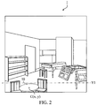
- FIG. 2 is a schematic diagram illustrating that a table shown in FIG. 1 is selected.
- FIG. 3A to FIG. 3E are schematic diagrams illustrating five continuous images related to the table shown in FIG. 2 .
- FIG. 4 is a schematic diagram illustrating that the table and the chair shown in FIG. 1 are selected.
- FIG. 5A to FIG. 5E are schematic diagrams illustrating five continuous images related to the table and the chair shown in FIG. 4 .
- FIG. 6 is a schematic diagram illustrating that the table and the chair shown in FIG. 1 are selected.
- FIG. 7A to FIG. 7E are schematic diagrams illustrating five continuous images related to the table and the chair shown in FIG. 6 .
- FIG. 1 is a schematic diagram illustrating a 2D image 1 .
- the 2D image 1 comprises a plurality of objects, such as a table 10 , chairs 12 , 14 , 16 , a piano 18 , and the like.
- the used technique and effects thereof for achieving the scopes of the invention are illustrated by several following preferred embodiments.
- the first preferred embodiment illustrates the principle of the image transforming method of the invention for transforming the table 10 in the 2D image into a 3D image.
- FIG. 2 is a schematic diagram illustrating that the table 10 shown in FIG. 1 is selected
- FIG. 3A to FIG. 3E are schematic diagrams illustrating five continuous images related to the table 10 shown in FIG. 2 .
- a user needs to select the table 10 (shown by dotted lines) and sets a base line Y 1 in the 2D image 1 .
- the base line Y 1 is a horizontal line.
- a center coordinate C(x, y) of the table 10 is calculated, and according to a position of the center coordinate C(x, y) relative to the base line Y 1 , whether the table 10 is located on a foreground or a background of the 2D image 1 is being judged.
- the center coordinate C(x, y) is calculated with the following formula.
- C ( x,y ) (sum( x )/ n ,sum( y )/ n ).
- n represents the amount of all pixels of the table 10
- sum(x) represents the sum of x-coordinate of each pixel
- sum(y) represents the sum of y-coordinate of each pixel.
- a displacement d is offered to the table 10 , and according to the center coordinate C of the table 10 , the table 10 is moved sequentially along a first direction (as the direction of arrow A 1 shown in FIG. 3A to FIG. 3E ) with the displacement d for five times, so as to generate five continuous images I 1 -I 5 , as shown in FIG. 3A to FIG. 3E . Finally, each of the continuous images I 1 -I 5 is outputted sequentially to generate a 3D image of the table 10 .
- the second preferred embodiment illustrates the principle of the image transforming method of the invention for transforming the 2D images of table 10 and chair 12 into 3D images.
- FIG. 4 is a schematic diagram illustrating that the table 10 and the chair 12 shown in FIG. 1 are selected
- FIG. 5A to FIG. 5E are schematic diagrams illustrating five continuous images related to the table 10 and the chair 12 shown in FIG. 4 .
- the user needs to select the table 10 and the chair 12 (shown by dotted line) and sets a base line Y 1 ′ in the 2D image 1 .
- the base line Y 1 ′ is a horizontal line.
- a center coordinate C 1 (x 1 , y 1 ) of the table 10 and a center coordinate C 2 (x 2 , y 2 ) of the chair are calculated, and according to the positions of the center coordinates C 1 (x 1 , y 1 ) and C 2 (x 2 , y 2 ) relative to the base line Y 1 ′, whether the table 10 and chair 12 are located on the foreground or background of the 2D image 1 is being judged.
- the y-coordinate y 1 and y 2 of the center coordinates C 1 and C 2 are located below the base line Y 1 ′, it is judged that the table 10 and the chair 12 are located on the foreground of the 2D image 1 .
- the table 10 and the chair 12 are sorted.
- the basis for sorting (1) if the distance from the center coordinate of the object to the base line is longer, the object is sorted as the former; (2) if the object extends upward from a bottom (border) of the 2D image 1 , the object is sorted as the former; and (3) if the distances from the center coordinates of two objects to the base line are the same, the first selected object is sorted as the former. Therefore, the chair 12 is sorted as the former to the table 10 .
- a displacement d 1 is offered to the table 10 and a displacement d 2 is offered to the chair 12 , and according to the center coordinate C 1 of the table 10 and the center coordinate C 2 of the chair 12 , the table 10 is moved sequentially along a first direction (as the direction of arrow A 1 shown in FIG. 5A to FIG. 5E ) with the displacement d 1 for five times and the chair 12 is moved sequentially along the first direction with the displacement d 2 for five times, so as to generate five continuous images I 1 ′-I 5 ′, as shown in FIG. 5A to FIG. 5E . Finally, each of the continuous images I 1 ′-I 5 ′ is outputted sequentially to generate the 3D images of the table 10 and the chair 12 .
- the third preferred embodiment illustrates the principle of the image transforming method of the invention for transforming the 2D images of table 10 and chair 16 into 3D images.
- FIG. 6 is a schematic diagram illustrating that the table 10 and the chair 16 shown in FIG. 1 are selected
- FIG. 7A to FIG. 7E are schematic diagrams illustrating five continuous images related to the table 10 and the chair 16 shown in FIG. 6 .
- the user needs to select the table 10 and the chair 16 (shown by dotted line) and sets a base line Y 1 ′′ in the 2D image 1 .
- the base line Y 1 ′′ is a horizontal line.
- a center coordinate C 1 (x 1 , y 1 ) of the table 10 and a center coordinate C 3 (x 3 , y 3 ) of the chair 16 are calculated, and according to the positions of the center coordinates C 1 (x 1 , y 1 ) and C 3 (x 3 , y 3 ) relative to the base line Y 1 ′′, whether the table 10 and chair 16 are located on the foreground or background of the 2D image 1 is being judged. As shown in FIG.
- a displacement d 1 is offered to the table 10 and a displacement d 3 is offered to the chair 16 , and according to the center coordinate C 1 of the table 10 and the center coordinate C 2 of the chair 16 , the table 10 is moved sequentially along a first direction (the direction of arrow A 1 shown in FIG. 7A to FIG. 7E ) with the displacement d 1 for five times and the chair 16 is moved sequentially along a second direction (the direction of arrow A 2 shown in FIG. 7A to FIG. 7E ) with a displacement d 3 for five times, so as to generate five continuous images I 1 ′′-I 5 ′′, as shown in FIG. 7A to FIG. 7E . Finally, each of the continuous images I 1 ′′-I 5 ′′ is outputted sequentially to generate the 3D images of the table 10 and the chair 16 .
- the first direction is opposite to the second direction.
- the said displacements and the number of the continuous images produced at the last step are capable of being designed by the designer according to particular applications. Accordingly, the invention is capable of being applied to various 3D displays, such as a slanted lenticular, a straight lenticular, a light polarizing plate, and the like. If the 3D displays are in the form of the light polarizing plates, only two continuous images need to be generated in the end.
- the method of the invention can transform a 2D image into a 3D image. It is very convenient for the users.
Abstract
Description
C(x,y)=(sum(x)/n,sum(y)/n).
Claims (11)
Applications Claiming Priority (3)
| Application Number | Priority Date | Filing Date | Title |
|---|---|---|---|
| TW95147234A | 2006-12-15 | ||
| TW095147234A TWI322969B (en) | 2006-12-15 | 2006-12-15 | Method capable of automatically transforming 2d image into 3d image |
| TW095147234 | 2006-12-15 |
Publications (2)
| Publication Number | Publication Date |
|---|---|
| US20080143716A1 US20080143716A1 (en) | 2008-06-19 |
| US7876321B2 true US7876321B2 (en) | 2011-01-25 |
Family
ID=39526568
Family Applications (1)
| Application Number | Title | Priority Date | Filing Date |
|---|---|---|---|
| US11/878,387 Expired - Fee Related US7876321B2 (en) | 2006-12-15 | 2007-07-24 | Method capable of automatically transforming 2D image into 3D image |
Country Status (2)
| Country | Link |
|---|---|
| US (1) | US7876321B2 (en) |
| TW (1) | TWI322969B (en) |
Cited By (1)
| Publication number | Priority date | Publication date | Assignee | Title |
|---|---|---|---|---|
| US20150109303A1 (en) * | 2013-10-23 | 2015-04-23 | Cornell University | Systems and methods for computational lighting |
Families Citing this family (9)
| Publication number | Priority date | Publication date | Assignee | Title |
|---|---|---|---|---|
| TWI383332B (en) * | 2009-05-08 | 2013-01-21 | Chunghwa Picture Tubes Ltd | Image processing device and method thereof |
| US9491432B2 (en) | 2010-01-27 | 2016-11-08 | Mediatek Inc. | Video processing apparatus for generating video output satisfying display capability of display device according to video input and related method thereof |
| TWI493505B (en) * | 2011-06-20 | 2015-07-21 | Mstar Semiconductor Inc | Image processing method and image processing apparatus thereof |
| CN102857772B (en) * | 2011-06-29 | 2015-11-11 | 晨星软件研发(深圳)有限公司 | Image treatment method and image processor |
| TWI489414B (en) * | 2011-07-25 | 2015-06-21 | Realtek Semiconductor Corp | 2d to 3d image conversion apparatus and method thereof |
| JP5771096B2 (en) * | 2011-08-31 | 2015-08-26 | 株式会社半導体エネルギー研究所 | Image processing method |
| KR101830966B1 (en) | 2011-09-21 | 2018-02-22 | 엘지전자 주식회사 | Electronic device and contents generation method for electronic device |
| TWI498854B (en) * | 2013-01-18 | 2015-09-01 | Chunghwa Picture Tubes Ltd | Method of auto-determination a three-dimensional image format |
| KR101802582B1 (en) * | 2014-11-24 | 2017-11-28 | 타이완 세미콘덕터 매뉴팩쳐링 컴퍼니 리미티드 | Layout optimization for integrated circuit design |
Citations (5)
| Publication number | Priority date | Publication date | Assignee | Title |
|---|---|---|---|---|
| US6434277B1 (en) * | 1998-07-13 | 2002-08-13 | Sony Corporation | Image processing apparatus and method, and medium therefor |
| US6515659B1 (en) * | 1998-05-27 | 2003-02-04 | In-Three, Inc. | Method and system for creating realistic smooth three-dimensional depth contours from two-dimensional images |
| US6590573B1 (en) * | 1983-05-09 | 2003-07-08 | David Michael Geshwind | Interactive computer system for creating three-dimensional image information and for converting two-dimensional image information for three-dimensional display systems |
| US7102633B2 (en) * | 1998-05-27 | 2006-09-05 | In-Three, Inc. | Method for conforming objects to a common depth perspective for converting two-dimensional images into three-dimensional images |
| US20080246759A1 (en) * | 2005-02-23 | 2008-10-09 | Craig Summers | Automatic Scene Modeling for the 3D Camera and 3D Video |
-
2006
- 2006-12-15 TW TW095147234A patent/TWI322969B/en not_active IP Right Cessation
-
2007
- 2007-07-24 US US11/878,387 patent/US7876321B2/en not_active Expired - Fee Related
Patent Citations (5)
| Publication number | Priority date | Publication date | Assignee | Title |
|---|---|---|---|---|
| US6590573B1 (en) * | 1983-05-09 | 2003-07-08 | David Michael Geshwind | Interactive computer system for creating three-dimensional image information and for converting two-dimensional image information for three-dimensional display systems |
| US6515659B1 (en) * | 1998-05-27 | 2003-02-04 | In-Three, Inc. | Method and system for creating realistic smooth three-dimensional depth contours from two-dimensional images |
| US7102633B2 (en) * | 1998-05-27 | 2006-09-05 | In-Three, Inc. | Method for conforming objects to a common depth perspective for converting two-dimensional images into three-dimensional images |
| US6434277B1 (en) * | 1998-07-13 | 2002-08-13 | Sony Corporation | Image processing apparatus and method, and medium therefor |
| US20080246759A1 (en) * | 2005-02-23 | 2008-10-09 | Craig Summers | Automatic Scene Modeling for the 3D Camera and 3D Video |
Cited By (2)
| Publication number | Priority date | Publication date | Assignee | Title |
|---|---|---|---|---|
| US20150109303A1 (en) * | 2013-10-23 | 2015-04-23 | Cornell University | Systems and methods for computational lighting |
| US9483815B2 (en) * | 2013-10-23 | 2016-11-01 | Cornell University | Systems and methods for computational lighting |
Also Published As
| Publication number | Publication date |
|---|---|
| TWI322969B (en) | 2010-04-01 |
| TW200825979A (en) | 2008-06-16 |
| US20080143716A1 (en) | 2008-06-19 |
Similar Documents
| Publication | Publication Date | Title |
|---|---|---|
| US7876321B2 (en) | Method capable of automatically transforming 2D image into 3D image | |
| US7796134B2 (en) | Multi-plane horizontal perspective display | |
| CN107193372B (en) | Projection method from multiple rectangular planes at arbitrary positions to variable projection center | |
| US20050219694A1 (en) | Horizontal perspective display | |
| TWI523488B (en) | A method of processing parallax information comprised in a signal | |
| US8189035B2 (en) | Method and apparatus for rendering virtual see-through scenes on single or tiled displays | |
| RU2519518C2 (en) | Stereoscopic image generator, method for stereoscopic image generator, and programme | |
| CN102905145B (en) | Stereoscopic image system, image generation method, image adjustment device and method thereof | |
| US20060221071A1 (en) | Horizontal perspective display | |
| JP2008083534A (en) | 3d image displaying method and apparatus | |
| US20060250390A1 (en) | Horizontal perspective display | |
| WO2002071764A1 (en) | Method and system for adjusting stereoscopic image to optimize viewing for image zooming | |
| US20120327077A1 (en) | Apparatus for rendering 3d images | |
| RU2707726C2 (en) | Image generation for autostereoscopic display | |
| KR100726933B1 (en) | Image signal processing method for auto convergence control method of two fixed cameras | |
| CN106559662B (en) | Multi-view image display apparatus and control method thereof | |
| JP2010128450A (en) | Three-dimensional display object, three-dimensional image forming apparatus, method and program for forming three-dimensional image | |
| CN105578171A (en) | Image signal processing method and device | |
| JP4270695B2 (en) | 2D-3D image conversion method and apparatus for stereoscopic image display device | |
| CN101566784A (en) | Method for establishing depth of field data for three-dimensional image and system thereof | |
| JP2013168781A (en) | Display device | |
| JP2006301094A (en) | Three-dimensional display method and three-dimensional display device | |
| TWI533663B (en) | Apparatus and method for processing 3-d image | |
| TWI771969B (en) | Method for rendering data of a three-dimensional image adapted to eye position and a display system | |
| Eum et al. | Super Multi-view Autostereoscopic 3D Representation on Mobile Display |
Legal Events
| Date | Code | Title | Description |
|---|---|---|---|
| AS | Assignment |
Owner name: QUANTA COMPUTER INC., TAIWAN Free format text: ASSIGNMENT OF ASSIGNORS INTEREST;ASSIGNORS:HSIEH, TUNG-LIN;LEE, WAN-CHING;HUANG, I-MING;REEL/FRAME:019663/0749 Effective date: 20070723 |
|
| STCF | Information on status: patent grant |
Free format text: PATENTED CASE |
|
| FPAY | Fee payment |
Year of fee payment: 4 |
|
| MAFP | Maintenance fee payment |
Free format text: PAYMENT OF MAINTENANCE FEE, 8TH YEAR, LARGE ENTITY (ORIGINAL EVENT CODE: M1552) Year of fee payment: 8 |
|
| FEPP | Fee payment procedure |
Free format text: MAINTENANCE FEE REMINDER MAILED (ORIGINAL EVENT CODE: REM.); ENTITY STATUS OF PATENT OWNER: LARGE ENTITY |
|
| LAPS | Lapse for failure to pay maintenance fees |
Free format text: PATENT EXPIRED FOR FAILURE TO PAY MAINTENANCE FEES (ORIGINAL EVENT CODE: EXP.); ENTITY STATUS OF PATENT OWNER: LARGE ENTITY |
|
| STCH | Information on status: patent discontinuation |
Free format text: PATENT EXPIRED DUE TO NONPAYMENT OF MAINTENANCE FEES UNDER 37 CFR 1.362 |
|
| FP | Lapsed due to failure to pay maintenance fee |
Effective date: 20230125 |