US7860607B2 - Method of estimating joint moment of bipedal walking body - Google Patents
Method of estimating joint moment of bipedal walking body Download PDFInfo
- Publication number
- US7860607B2 US7860607B2 US10/564,073 US56407304A US7860607B2 US 7860607 B2 US7860607 B2 US 7860607B2 US 56407304 A US56407304 A US 56407304A US 7860607 B2 US7860607 B2 US 7860607B2
- Authority
- US
- United States
- Prior art keywords
- leg
- joint
- floor reaction
- reaction force
- coordinate system
- Prior art date
- Legal status (The legal status is an assumption and is not a legal conclusion. Google has not performed a legal analysis and makes no representation as to the accuracy of the status listed.)
- Expired - Fee Related, expires
Links
- 0 CCCNCC(C)* Chemical compound CCCNCC(C)* 0.000 description 1
Images


Classifications
-
- B—PERFORMING OPERATIONS; TRANSPORTING
- B62—LAND VEHICLES FOR TRAVELLING OTHERWISE THAN ON RAILS
- B62D—MOTOR VEHICLES; TRAILERS
- B62D57/00—Vehicles characterised by having other propulsion or other ground- engaging means than wheels or endless track, alone or in addition to wheels or endless track
- B62D57/02—Vehicles characterised by having other propulsion or other ground- engaging means than wheels or endless track, alone or in addition to wheels or endless track with ground-engaging propulsion means, e.g. walking members
-
- A—HUMAN NECESSITIES
- A61—MEDICAL OR VETERINARY SCIENCE; HYGIENE
- A61B—DIAGNOSIS; SURGERY; IDENTIFICATION
- A61B5/00—Measuring for diagnostic purposes; Identification of persons
- A61B5/103—Detecting, measuring or recording devices for testing the shape, pattern, colour, size or movement of the body or parts thereof, for diagnostic purposes
- A61B5/1036—Measuring load distribution, e.g. podologic studies
- A61B5/1038—Measuring plantar pressure during gait
-
- A—HUMAN NECESSITIES
- A61—MEDICAL OR VETERINARY SCIENCE; HYGIENE
- A61B—DIAGNOSIS; SURGERY; IDENTIFICATION
- A61B5/00—Measuring for diagnostic purposes; Identification of persons
- A61B5/103—Detecting, measuring or recording devices for testing the shape, pattern, colour, size or movement of the body or parts thereof, for diagnostic purposes
- A61B5/11—Measuring movement of the entire body or parts thereof, e.g. head or hand tremor, mobility of a limb
- A61B5/112—Gait analysis
-
- A—HUMAN NECESSITIES
- A61—MEDICAL OR VETERINARY SCIENCE; HYGIENE
- A61B—DIAGNOSIS; SURGERY; IDENTIFICATION
- A61B5/00—Measuring for diagnostic purposes; Identification of persons
- A61B5/103—Detecting, measuring or recording devices for testing the shape, pattern, colour, size or movement of the body or parts thereof, for diagnostic purposes
- A61B5/11—Measuring movement of the entire body or parts thereof, e.g. head or hand tremor, mobility of a limb
- A61B5/1121—Determining geometric values, e.g. centre of rotation or angular range of movement
-
- A—HUMAN NECESSITIES
- A61—MEDICAL OR VETERINARY SCIENCE; HYGIENE
- A61B—DIAGNOSIS; SURGERY; IDENTIFICATION
- A61B5/00—Measuring for diagnostic purposes; Identification of persons
- A61B5/45—For evaluating or diagnosing the musculoskeletal system or teeth
- A61B5/4528—Joints
-
- B—PERFORMING OPERATIONS; TRANSPORTING
- B62—LAND VEHICLES FOR TRAVELLING OTHERWISE THAN ON RAILS
- B62D—MOTOR VEHICLES; TRAILERS
- B62D57/00—Vehicles characterised by having other propulsion or other ground- engaging means than wheels or endless track, alone or in addition to wheels or endless track
- B62D57/02—Vehicles characterised by having other propulsion or other ground- engaging means than wheels or endless track, alone or in addition to wheels or endless track with ground-engaging propulsion means, e.g. walking members
- B62D57/032—Vehicles characterised by having other propulsion or other ground- engaging means than wheels or endless track, alone or in addition to wheels or endless track with ground-engaging propulsion means, e.g. walking members with alternately or sequentially lifted supporting base and legs; with alternately or sequentially lifted feet or skid
-
- A—HUMAN NECESSITIES
- A61—MEDICAL OR VETERINARY SCIENCE; HYGIENE
- A61B—DIAGNOSIS; SURGERY; IDENTIFICATION
- A61B5/00—Measuring for diagnostic purposes; Identification of persons
- A61B5/103—Detecting, measuring or recording devices for testing the shape, pattern, colour, size or movement of the body or parts thereof, for diagnostic purposes
- A61B5/107—Measuring physical dimensions, e.g. size of the entire body or parts thereof
- A61B5/1071—Measuring physical dimensions, e.g. size of the entire body or parts thereof measuring angles, e.g. using goniometers
-
- A—HUMAN NECESSITIES
- A61—MEDICAL OR VETERINARY SCIENCE; HYGIENE
- A61H—PHYSICAL THERAPY APPARATUS, e.g. DEVICES FOR LOCATING OR STIMULATING REFLEX POINTS IN THE BODY; ARTIFICIAL RESPIRATION; MASSAGE; BATHING DEVICES FOR SPECIAL THERAPEUTIC OR HYGIENIC PURPOSES OR SPECIFIC PARTS OF THE BODY
- A61H3/00—Appliances for aiding patients or disabled persons to walk about
Definitions
- the present invention relates to a method of estimating the moment (joint moment) acting on a joint of each leg of a bipedal walking body, such as a human being or a bipedal walking robot.
- a walking aid apparatus for assisting a human being in walking
- a bipedal walking robot also, there are cases where it is required to grasp a joint moment actually acting on each joint of a leg to conduct the operation control.
- Patent Document 1 Japanese Unexamined Patent Application Publication No. 2003-89083
- a technique for estimating a joint moment of a leg of a bipedal walking body such as a human being.
- a displacement amount (rotational angle) of each joint of a leg of the bipedal walking body, the acceleration of a predetermined part, and angular velocity are measured using required sensors, and then the measurement data and a rigid link model of the bipedal walking body or the like are used to estimate a floor reaction force (translational floor reaction force) acting on each leg and the position of an acting point thereof.
- a floor reaction force translational floor reaction force
- the rigid link model is a model representing a structure of the bipedal walking body in terms of an assembly formed by connecting a plurality of rigid elements by a plurality of joint elements.
- the rigid link model is used to estimate the position of the overall center-of-gravity of the bipedal walking body, the positions and the postures of corresponding rigid bodies of the bipedal walking body (thighs, cruses, waist, etc.) respectively associated with the rigid elements and the joint elements, and the positions and the postures of joints (knee joints, hip joints, etc.), and it is also used as the basis of the model for describing a dynamic behavior of the bipedal walking body.
- the weights, the lengths, and the positions of the centers of gravity thereof are collaterally set beforehand.
- the estimated floor reaction force and the position of the acting point thereof and the rigid link model are used to estimate the joint moments of the knee joints or the hip joints of the legs by arithmetic processing based on an inverse dynamic model.
- the inverse dynamic model is generally described as a dynamic model for estimating a reaction force or a moment, which is an internal force of an object, an external force acting on the object and positional information being known (the external force and the positional information being input parameters), and it represents the relationship between motions of the object (a positional time-series pattern) and forces or moments acting on the object.
- the inverse dynamic model is constructed on the basis of dynamic equations related to motions (translational motions and rotational motions) of the rigid elements of the rigid link model, and joint moments of each leg are estimated in order, the moment of the joint closest to the acting point of a floor reaction force being the first to be estimated.
- the motion (two-dimensional motion) of a human being on the plane (sagittal plane) of a vertical posture with the lateral direction of the human being defined as a normal line direction is grasped so as to estimate a joint moment (a moment about a lateral axis).
- joints such as a hip joint, of a leg of the human being are capable of three-dimensional (spatial) motions, including the motions of a leg in the bending and stretching directions, and they are capable of a motion of, for example, moving each leg in the lateral directions by rotation about a substantially longitudinal axis of a hip joint (so-called abduction and adduction) or a twisting motion (turning motion) of each leg by rotation about a substantially vertical axis of the hip joint. Therefore, there are many cases where bending motions of the legs are not performed on the sagittal plane of a vertical posture when a human being moves. In such cases, there has been likelihood that the accuracy of estimating joint moments in the bending/stretching directions of the legs deteriorates in an embodiment of Patent Document 1 mentioned above.
- the joints of the legs of the human being as a bipedal walking body are capable of performing complicated motions and are apt to be subject to restrictions on the mounting locations or mounting forms of the sensors for detecting the displacement amounts. For this reason, it is usually difficult to grasp every component of the three-dimensional displacement amounts of the joints with sufficiently high accuracy. Further, the accuracy of the displacement amount of a joint grasped from an output of a sensor tends to vary, depending on a posture state or the like of a leg.
- the present invention has been made in view of the above background, and it is an object of the present invention to provide a method of estimating a joint moment of a bipedal walking body that permits enhanced stability of an estimated value of a joint moment in bending/stretching directions of a leg, while securing estimation accuracy, considering three-dimensional motions of the bipedal walking body.
- At least a rotational angle about the axis that is substantially perpendicular to the leg plane can be grasped with relatively high accuracy by using a sensor, such as a potentiometer or a rotary encoder.
- a method of estimating a joint moment of a bipedal walking body in accordance with the present invention includes a first step for sequentially grasping the displacement amounts of a plurality of joints, including at least an ankle joint, a hip joint and a knee joint of each leg of a bipedal walking body, a second step for sequentially grasping the positions and/or postures of corresponding rigid bodies of the bipedal walking body that are associated with rigid elements of a rigid link model by using at least the rigid link model wherein the rigid link model being established beforehand to express the bipedal walking body in the form of a link assembly composed of a plurality of the rigid elements and a plurality of joint elements and the grasped displacement amounts of the joints, a third step for grasping the acceleration of a preset reference point of the bipedal walking body by using at least an output of an acceleration sensor attached to a predetermined region of the bipedal walking body, and a fourth step for sequentially grasping a floor reaction force acting on each leg and the position of an acting point of the
- any techniques may be used to grasp the floor reaction forces and the acting points thereof.
- load sensors or pressure distribution sensors may be attached to the soles of the feet of the legs thereby to grasp floor reaction forces or the positions of the acting points thereof from the outputs of the sensors.
- a bipedal walking body may move on a floor provided with a force plate having load sensors so as to grasp floor reaction forces or the positions of the acting points thereof from the outputs of the force place.
- the techniques to be explained in third to seventh inventions, which will be discussed later, may be used to grasp floor reaction forces and the positions of the acting points thereof.
- the amounts of rotations of the hip joint, the knee joint, and the ankle joint of the leg about the axis that is substantially perpendicular to the leg plane, which are grasped in the first step, can be grasped with relatively high accuracy by using potentiometers or rotary encoders, as described above.
- the positions and/or the postures of corresponding rigid bodies of each leg on a leg plane can be grasped with relatively high accuracy without depending on the three-dimensional motions, including motions (abduction, external rotation, adduction, internal rotation and the like of each leg) other than two-dimensional motions of each leg on the leg plane.
- the acceleration of the reference point of the bipedal walking body and the floor reaction force acting on each leg and the position of the acting point thereof are grasped in terms of three-dimensional amounts (vector amounts represented by a certain three-dimensional coordinate system), considering the spatial motions of the bipedal walking body, and then they are projected onto a leg plane related to the leg on the basis of the displacement amount (three-dimensional amount) of the hip joint of the leg so as to obtain the two-dimensional amounts of the acceleration of the reference point and the floor reaction force and the acting point thereof on the leg plane (technically, the components on a plane parallel to the leg plane).
- three-dimensional amounts vector amounts represented by a certain three-dimensional coordinate system
- the two-dimensional amounts of the acceleration of the reference point and the floor reaction force and the acting point thereof on the leg plane and the positions and/or the postures of the corresponding rigid bodies on the leg plane grasped as described above are used to estimate a component of the joint moment acting on at least one joint of the leg on the basis of an inverse dynamic model on the leg plane, the component being the one about an axis that is substantially perpendicular to the leg plane.
- the stability of estimated values can be enhanced while considering three-dimensional motions of a bipedal walking body and securing the estimation accuracy of joint moments in the bending and stretching directions of each leg.
- projecting the acceleration of the reference point, the floor reaction force, and the position of the acting point of the floor reaction force mentioned above onto the leg plane is equivalent to coordinate-converting the vector of the acceleration, the vector of the floor reaction force, and the vector of the position of the acting point, which are expressed in terms of an arbitrary three-dimensional coordinate system, into vector amounts expressed in terms of a three-dimensional coordinate system that includes the leg plane as one coordinate plane, and then extracting the components of the leg plane of the vector amounts.
- the region of the bipedal walking body where the acceleration sensor is installed and the region where the reference point is set may be different from each other; however, it is basically preferred that they are installed in the same region (a corresponding rigid body associated with a certain rigid element of the rigid link model), and it is particularly preferred that the part is the waist.
- the acceleration of the reference point grasped in the third step, and the floor reaction force and the position of the acting point of the floor reaction force grasped in the fourth step are preferably three-dimensional amounts expressed in terms of a body coordinate system set beforehand as a three-dimensional coordinate system fixed to one predetermined rigid element of the rigid link model (a second invention).
- the three-dimensional amounts of the acceleration of the reference point, etc. may be basically expressed by any three-dimensional coordinate system. If, for example, they are expressed by a three-dimensional coordinate system that includes a vertical axis and a horizontal axis, then it is necessary to grasp an inclination angle of a corresponding rigid body of the bipedal walking body relative to the vertical direction by using an inclination sensor, such as a gyro sensor.
- the inclination sensor is usually apt to incur an integral error or an error caused by an influence of inertial acceleration due to a motion of the bipedal walking body. For this reason, it is desirable to estimate a joint moment without using the information on an inclination of a portion of the bipedal walking body as much as possible.
- the acceleration of the reference point, the floor reaction force, and the position of the acting point of the floor reaction force are grasped as three-dimensional amounts in the body coordinate system.
- a joint moment is estimated by grasping the acceleration of the reference point, etc. in terms of three-dimensional amounts in the body coordinate system, making it possible to minimize the arithmetic processing that uses inclination information of the bipedal walking body.
- causes for errors in estimating joint moments are lessened, allowing the accuracy of the estimated value to be secured.
- grasping the position of the acting point of a floor reaction force requires the information on the inclination angle (the inclination angle relative to the vertical direction) of a certain corresponding rigid body of the bipedal walking body.
- the acceleration of the reference point and a floor reaction force can be grasped as three-dimensional amounts in a body coordinate system without using information on an inclination angle.
- the value of a floor reaction force in the body coordinate system (three-dimensional amount) can be grasped also, for example, from outputs of a load sensor or a pressure distribution sensor attached to the sole of a foot portion of a bipedal walking body.
- a load sensor or the like attached to sole of a foot portion tends to interfere with smooth walking.
- the values of floor reaction force vectors in the body coordinate system are grasped by, for example, the following technique.
- the technique includes a fifth step for sequentially determining the position of the overall center-of-gravity of the bipedal walking body in the body coordinate system by using the displacement amounts of joints of the bipedal walking body grasped in the first step and by using the rigid link model, a sixth step for sequentially determining the acceleration of the overall center-of-gravity on the body coordinate system from the time series data of the position of the overall center-of-gravity and the acceleration of the origin of the body coordinate system grasped using at least an output of the acceleration sensor, and a seventh step for sequentially determining whether a motion state of the bipedal walking body is a one-leg supporting state in which only one of a pair of legs is in contact with the ground or a two-leg supporting state in which both legs are in contact with the ground.
- the fourth step estimates the value of a floor reaction force on the body coordinate system according to a dynamic equation of the overall center-of-gravity of the bipedal walking body expressed by the acceleration of the overall center-of-gravity determined in the sixth step, the total weight of the bipedal walking body, and the floor reaction force acting on the leg in contact with the ground.
- the fourth step grasps the values of the floor reaction forces acting on the two legs, respectively, in the body coordinate system, on the basis of a dynamic equation of the overall center-of-gravity of the bipedal walking body expressed by the acceleration of the overall center-of-gravity determined in the sixth step, the total weight of the bipedal walking body, and the floor reaction force acting on the two legs, respectively, and the expression of the relationship between the relative position of a specific part of the leg with respect to the overall center-of-gravity of the bipedal walking body and the floor reaction forces acting on the leg, which is established on the assumption that the floor reaction forces acting on the legs are the vectors acting toward the overall center-of-gravity of the bipedal walking body from the specific part specified beforehand in the vicinity of the bottom end of the leg (a third invention).
- the floor reaction force acting on the leg in contact with the ground is determined on the basis of the dynamic equation of the overall center-of-gravity (the dynamic equation related to the translational motion of the overall center-of-gravity) of the bipedal walking body in the one-leg supporting state and the two-leg supporting state.
- floor reaction forces can be estimated without using load sensors or the like that would interfere with or add load to the walking of the bipedal walking body.
- a floor reaction force acting on each of the legs cannot be identified by using only the dynamic equation of the overall center-of-gravity (the dynamic equation related to the translational motion of the overall center-of-gravity); however, the floor reaction force of each leg can be estimated by additionally using the expression of the relationship between the relative position of a specific part of the leg with respect to the overall center-of-gravity of the bipedal walking body and the floor reaction forces acting on the leg, which is established on the assumption that the floor reaction forces acting on the legs are the vectors acting toward the overall center-of-gravity of the bipedal walking body from the specific part (e.g., the ankle joint of each leg or a floor reaction force acting point) specified beforehand in the vicinity of the bottom end of the leg.
- the specific part e.g., the ankle joint of each leg or a floor reaction force acting point
- the values in the body coordinate system thereof are sequentially determined, so that the dynamic equation of the overall center-of-gravity can be described simply by coordinate component values of a body coordinate system.
- the expression of relationship between the relative position of a specific part of the leg with respect to the overall center-of-gravity of the bipedal walking body and the floor reaction forces acting on the leg can be described simply by coordinate component values of the body coordinate system.
- the value (three-dimensional amount) of a floor reaction force on a body coordinate system can be determined without grasping the inclination state (the inclination state relative to the vertical direction) of a corresponding rigid body to which a body coordinate system is fixed.
- the acting points of floor reaction forces can be estimated by, for example, attaching pressure distribution sensors to the soles of the feet of a bipedal walking body so as to use their detection outputs; they can be also estimated by, for example, the following technique.
- the technique includes an eighth step for sequentially grasping the inclination angle of a corresponding rigid body of a bipedal walking body relative to the vertical direction, which corresponds to one predetermined rigid element of the rigid link model, a ninth step for determining whether each of the legs of the bipedal walking body is in contact with the ground, and a tenth step for grasping the positional relationship among at least the overall center-of-gravity of the bipedal walking body, the ankle joint of each leg in contact with the ground, and the metatarsophalangeal joint of the foot portion of the leg, and the vertical position of the ankle joint by using the inclination angle grasped in the eighth step, a displacement amount of each joint of the bipedal walking body grasped in the first step, and the rigid link model.
- the fourth step estimates the position in a horizontal plane of the acting point of a floor reaction force acting on a leg on the basis of the positional relationship among the overall center-of-gravity, the ankle joint of each leg in contact with the ground and the metatarsophalangeal joint of the foot portion of the leg grasped in the tenth step, and also estimates the vertical position of the acting point of a floor reaction force acting on the leg on the basis of the vertical position of the ankle joint of the leg (a fourth invention).
- the position of the acting point in the horizontal plane of a floor reaction force acting on a leg of the bipedal walking body, the leg being in contact with the ground is closely connected with the relative positional relationship among the ankle joint and the metatarsophalangeal joint of the foot portion of the leg, and the overall center-of-gravity of the bipedal walking body.
- the vertical position of the acting point of a floor reaction force has a substantially constant correlation with the vertical position of an ankle joint of a leg.
- the positional relationship among the overall center-of-gravity of the bipedal walking body, the ankle joint of each leg in contact with the ground and the metatarsophalangeal joint of the foot portion of the leg, and the vertical position of the ankle joint can be grasped by using the inclination angle of the corresponding rigid body of the bipedal walking body relative to the vertical direction grasped in the eighth step, the displacement amount of each joint of the bipedal walking body grasped in the first step, and the rigid link model.
- Grasping the acting point of a floor reaction force as described above makes it possible to grasp the acting point of a floor reaction force without installing pressure distribution sensors on the soles of the feet of legs. Moreover, the elimination of need for installing pressure distribution sensors on the soles of the feet to which relatively high load tends to be instantly applied provides an advantage in the aspect of durability of an apparatus configuration for estimating joint moments.
- the fourth invention may be combined with the second invention or the third invention.
- the position of the acting point of a floor reaction force on the body coordinate system can be determined by grasping the position in a horizontal plane and the vertical position of the acting point of the floor reaction force as described above, and then by using at least the position in the horizontal plane, the vertical position, and the inclination angle grasped in the eighth step.
- the position in the horizontal plane (the position in a longitudinal direction and a lateral direction of the bipedal walking body) of the acting point of a floor reaction force can be grasped as described below. If the overall center-of-gravity exists at the rear side of the bipedal walking body in the longitudinal direction with respect to the ankle joint of the leg in contact with the ground, then the fourth step estimates the position in the horizontal plane of the ankle joint of the leg (the position in the longitudinal direction and the lateral direction) as the position in the horizontal plane (the position in the longitudinal direction and the lateral direction) of the acting point of the floor reaction force acting on the leg; if the overall center-of-gravity exists at the front side of the bipedal walking body in the longitudinal direction with respect to the metatarsophalangeal joint of the foot portion of the leg in contact with the ground, then the fourth step estimates the position in the horizontal plane of the metatarsophalangeal joint of the foot portion of the leg (the position in the longitudinal direction and the lateral direction) as the position in the
- the position in the horizontal plane (the position in the longitudinal direction and the lateral direction) of the ankle joint of the leg can be estimated as the position in the horizontal plane (the position in the longitudinal direction and the lateral direction) of the acting point of the floor reaction force acting on the leg.
- the leg is normally in contact with the ground at a toe of the foot portion thereof and the contact location is substantially directly below the metatarsophalangeal joint of the foot portion of the leg. Therefore, in this case, the position in the horizontal plane (the position in the longitudinal direction and the lateral direction) of the metatarsophalangeal joint of the foot portion of the leg can be estimated as the position in the horizontal plane (the position in the longitudinal direction and the lateral direction) of the acting point of the floor reaction force acting on the leg.
- the position of the acting point of the floor reaction force in the longitudinal direction substantially coincides with the position of the overall center-of-gravity in the longitudinal direction.
- the foot portion can be regarded as a rigid body that approximately extends from an ankle joint to a metatarsophalangeal joint, so that the acting point of a floor reaction force can be considered to exist on a segment obtained by projecting a segment that connects the ankle joint and the metatarsophalangeal joint onto a floor surface.
- the position in the horizontal plane (the position in the longitudinal direction and the lateral direction) of the point at which the overall center-of-gravity and the longitudinal position agree on a segment that connects the ankle joint and the metatarsophalangeal joint of a leg can be estimated as the position in the horizontal plane (the position in the longitudinal direction and the lateral direction) of the acting point of the floor reaction force acting on the leg.
- the fourth step estimates the vertical position of the acting point of a floor reaction force acting on a leg in contact with the ground as the position away downward in the vertical direction by a predetermined value, which has been specified beforehand, from the vertical position of the ankle joint of the leg grasped in the tenth step (a sixth invention).
- the ankle joint of the leg in contact with the ground during walking or the like of the bipedal walking body is generally located at a constant height from a floor surface.
- the position away downward in the vertical direction by a predetermined value which has been set beforehand (a predetermined value corresponding to the constant height) from the vertical position of the ankle joint of the leg can be estimated as the vertical position of the acting point of a floor reaction force.
- the height of the ankle joint of the leg in contact with the ground is generally constant. If only a portion adjacent to the toe side of a bottom surface of a foot portion of a leg is in contact with the ground when the bipedal walking body is moving, then the height of the ankle joint of the leg from a floor surface will be slightly greater than in a case where substantially the entire sole of the foot portion or a portion adjacent to the heel is in contact with the ground. Hence, in order to further improve the accuracy of estimating the vertical position of the acting point of a floor reaction force, the following is preferably performed in the sixth invention.
- the fourth step estimates the vertical position of the acting point of the floor reaction force by using a vertical distance between the ankle joint and the metatarsophalangeal joint determined from the vertical position of the ankle joint and the vertical position of the metatarsophalangeal joint, which have been grasped in the tenth step, in place of the predetermined value if it is determined in the ninth step that only the portion adjacent to the toe side out of the portion adjacent to the toe side and the portion adjacent to the heel side of the foot portion is in contact with the ground (a seventh invention).
- FIG. 1 is a diagram schematically showing an overall apparatus construction in an embodiment in which the present invention has been applied to a human being as a bipedal walking body
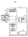
- FIG. 2 is a block diagram showing the construction of a sensor box installed on the apparatus shown in FIG. 1 ,
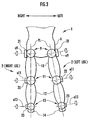
- FIG. 3 is a diagram showing a relationship between the rotational angles of joints detected by joint displacement sensors installed on the apparatus shown in FIG. 1 and leg planes (a front view of the lower body of the human being), and
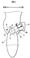
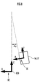
- FIG. 4 is a diagram for explaining the detection of the rotational angle of a hip joint by a joint displacement sensor of a hip joint in the apparatus shown in FIG. 1 (a side view of a portion around the waist of the human being).
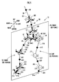
- FIG. 5 is a perspective view showing a rigid link model and a leg plane used in the embodiment
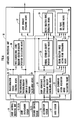
- FIG. 6 is a block diagram showing a functional means of an arithmetic processing device shown in FIG. 2 ,
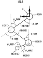
- FIG. 7 is a diagram for explaining the processing for determining a posture of a leg by a means for calculating a two-dimensional leg posture and the position of the center-of-gravity of an element shown in FIG. 6 , and
- FIG. 8 is a diagram for explaining an example of coordinate conversion between a sensor coordinate system and a body coordinate system in the embodiment.
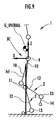
- FIG. 9 is a diagram for explaining a technique for estimating a floor reaction force vector in a one-leg supporting state of the bipedal walking body
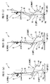
- FIGS. 10( a ) and ( b ) are diagrams for explaining a technique for estimating floor reaction force vectors in a two-leg supporting state of the bipedal walking body
- FIGS. 11( a ) to ( c ) are diagrams for explaining a technique for estimating the acting points of floor reaction force vectors
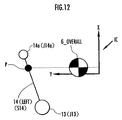
- FIG. 12 is a diagram for explaining a technique for estimating a component in the Y-axis direction of the acting point of a floor reaction force vector in the state shown in FIG. 11 ( b ),
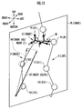
- FIG. 13 is a diagram for explaining the processing of a leg plane projecting means shown in FIG. 6 .
- FIG. 14 is a diagram for explaining the arithmetic processing by an inverse dynamic model for determining joint moments.
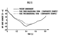
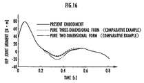
- FIG. 15 and FIG. 16 are graphs showing the transition of an estimated value of the joint moment of a hip joint and an estimated value of the joint moment of a knee joint, respectively, when the human being walks,
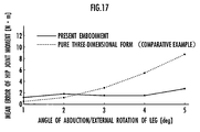
- FIG. 17 is a graph showing a relationship between an abduction or external rotation angle of a leg and an error of an estimated value of a joint moment of a hip joint when the human being walks,
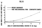
- FIG. 18 is a graph showing a relationship between an abduction or external rotation angle of a leg and an error of an estimated value of a joint moment of a knee joint when the human being walks,
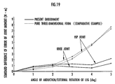
- FIG. 19 is a graph showing a relationship between abduction or external rotation angles of a leg and standard differences of errors of estimated values of joint moments of a knee joint and a hip joint when the human being walks, and
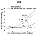
- FIG. 20 is a graph showing a relationship between abduction or external rotation angles of a leg and maximum errors of estimated values of joint moments of a knee joint and a hip joint when the human being walks.
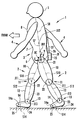
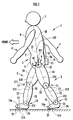
- FIG. 1 is a diagram schematically showing an overall apparatus construction in an embodiment in which the present invention has been applied to a human being as a bipedal walking body.
- the construction of a human being 1 is roughly divided into a pair of right and left legs 2 , 2 , a body 3 , a pair of right and left arms 4 , 4 , and a head 5 .
- the body 3 is constructed of a waist 6 , an abdomen 7 , and a chest 8 , and the waist 6 is connected to the legs 2 and 2 , respectively, through the intermediary of a pair of right and left hip joints 9 , 9 .
- each leg 2 is provided with a thigh 10 extending from a hip joint 9 , a crus 12 extending from the distal end of the thigh 10 through the intermediary of a knee joint 11 , and a foot 14 extending from the distal end of the crus 12 through the intermediary of an ankle joint 13 .
- a sensor box 15 is attached to the rear surface of the waist 6 through a member, such as a belt, which is not shown.
- the sensor box 15 houses an acceleration sensor 16 for detecting accelerations in 3-axis directions (translational accelerations), a gyro sensor 17 for detecting angular velocities in 3-axis directions (about 3 axes), an arithmetic processing unit 18 constructed using a microcomputer, a light emitter/receiver 19 for emitting light to be introduced into optical fibers 26 and 27 , which will be discussed hereinafter, and receiving return light, and a battery 20 as a power source of the electronic units, such as the arithmetic processing unit 18 , as shown in the block diagram of FIG. 2 .
- the acceleration sensor 16 and the gyro sensor 17 are secured to the waist 6 through the intermediary of the sensor box 15 so as to move integrally with the waist 6 .
- the hip joint 9 , the knee joint 11 , and the ankle joint 13 of each leg 2 are provided with joint displacement sensors 21 , 22 and 23 for detecting the displacement amounts of the respective joints through the intermediary of a member, such as a belt, which is not shown.
- a displacement amount detected by the joint displacement sensor 21 of the hip joint 9 is a rotational angle about three axes of the hip joint 9 (a three-dimensional amount composed of a set of rotational angles about these three axes)
- a displacement amount detected by the joint displacement sensor 22 of the knee joint 11 is a rotational angle about one axis of the knee joint 11
- a displacement amount detected by the joint displacement sensor 22 of the ankle joint 13 is a rotational angle about one axis of the ankle joint 13 .
- one of the rotational angles detected by the joint displacement sensors 21 and the axes of rotation of the rotational angles detected by the joint displacement sensors 22 and 23 are axes a 9 , a 11 , and a 13 that are substantially perpendicular to a leg plane PL as the plane passing substantially the centers of the hip joint 9 , the knee joint 11 , and the ankle joint 13 , respectively, of a leg 2 to which the sensors are attached, as shown in FIG. 3 .
- FIG. 3 is a diagram of the lower body of the human being 1 observed from the front side, the joint displacement sensors 21 to 23 being attached to each leg 2 .
- the leg plane PL is a plane perpendicular to the paper surface of the drawing.
- the leg plane LP is a plane wherein the central points of the hip joint 9 , the knee joint 11 , and the ankle joint 13 of a leg 2 exist when the corresponding leg 2 is bent at the knee joint 11 to bend the leg 2 .
- the leg 2 is bent in a state wherein the central points of the joints 9 , 11 , and 13 are positioned substantially on the leg plane PL.
- the leg plane PL corresponding to the left leg 2 inclines.
- the joint displacement sensors 21 to 23 detect the rotational angles about the aforesaid axes of rotation a 9 , a 11 , and a 13 of the joints 9 , 11 , and 13 , respectively, by, for example, a potentiometer or a rotary encoder.
- the joint displacement sensor 21 is connected to the sensor box 15 through the intermediary of an elastic member 50 shaped like a flat plate formed of rubber or the like.
- the end of the elastic member 50 adjacent to the sensor box 15 is connected to the sensor box 15 through the intermediary of a hard rigid member 50 a extended from the sensor box 15 .
- the joint displacement sensor 21 detects, for example, the rotational angle of the hip joint 9 about an axis of rotation b 9 in the direction in which the elastic member 50 extends (the rotational angle in the direction in which the elastic member 50 is twisted) and the rotational angle of the hip joint 9 about an axis of rotation c 9 orthogonal to the axis of rotation b 9 (the rotational angle in which the elastic member 50 is flexed) by using a distortion sensor, not shown, for detecting displacement amounts of the elastic member 50 , or an optical fiber to be discussed later.
- the aforesaid axes of rotation b 9 and c 9 are parallel to the leg plane PL.
- ground contact sensors 24 and 25 are provided on the soles of the foot portions 14 of the legs 2 (specifically, on the bottom surfaces of the shoes attached to the foot portions 14 ).
- the ground contact sensor 24 is provided at the location directly below the ankle joint 13 (heel) and the ground contact sensor 25 is provided at the location directly below a metatarsophalangeal joint 14 a of the foot 14 (the joint of the root of the thumb of the foot 14 ) (toe).
- These ground contact sensors 24 and 25 are sensors that output ON/OFF signals indicating whether the locations where they are installed are in contact with the ground.
- the detection outputs of the joint displacement sensors 21 , 22 and 23 , and the ground contact sensors 24 and 25 are supplied to the arithmetic processing unit 18 of the sensor box 15 through signal lines (not shown).
- the two optical fibers 26 and 27 are extendedly provided from the sensor box 15 upward along the rear surface of the body 3 , and the distal ends thereof are fixed to the rear surface of the abdomen 7 and the rear surface of the chest 8 , respectively, through the intermediary of a member, such as belts, which are not shown.
- the optical fibers 26 and 27 are constituents of a detecting means for detecting the inclination angles (inclination angles on sagittal planes) of the abdomen 7 and the chest 8 , respectively, relative to the waist 6 .
- the measurement of the inclination angles of the abdomen 7 and the chest 8 by using these optical fibers 26 and 27 is accomplished by the following technique.
- the technique for measuring the inclination angle of the abdomen 7 by using the optical fiber 26 will be taken as an example and representatively explained.
- Light of a predetermined intensity is introduced into the optical fiber 26 from the light emitter/receiver 19 provided in the sensor box 15 (shown in FIG. 2 ), and the introduced light is reflected at the distal end of the optical fiber 26 to be back into the sensor box 15 .
- the quantity of the returned light (the intensity of the returned light) is detected by the light emitter/receiver 19 .
- the optical fiber 26 is provided with a plurality of notches (not shown) that admits slight leakage of light arranged in the lengthwise direction with intervals provided among them.
- the return amount of the light back into the sensor box 15 corresponds to the inclination angle of the abdomen 7 , so that the inclination angle of the abdomen 7 relative to the waist 6 is measured by detecting the return amount.
- a detection output of the light emitter/receiver 19 based on the return amount of light of the optical fiber 25 corresponds to the inclination angle of the abdomen 7 relative to the waist 6 , and it is supplied to the arithmetic processing unit 18 as a signal indicating the inclination angle.
- the technique for measuring an inclination angle of the chest 8 by using the optical fiber 27 is the technique for measuring an inclination angle of the chest 8 by using the optical fiber 27 .
- the rotational angles of the hip joints 9 , the knee joints 11 , and the ankle joints 13 detected by the joint displacement sensors 21 , 22 , and 23 , respectively, are the rotational angles whose reference (zero point) is defined as the state wherein the human being 1 stands in an upright posture with both foot portions 14 and 14 oriented forward in parallel (hereinafter referred to as the reference posture state of the human being 1 ).
- FIG. 5 shows the rigid link model S 1 and the coordinate system.
- the rigid link model S 1 is shown also in FIG. 1 by virtual lines.
- the rigid link model S 1 expresses the human being 1 in the form of a link assembly composed of nine rigid elements and eight joint elements.
- the rigid link model S 1 is roughly divided into a pair of leg portions S 2 , S 2 respectively corresponding to the legs 2 of the human being 1 , and the upper body SU corresponding to the body (the portion above the waist 6 ) of the human being 1 .
- the upper body SU is constructed as a link assembly formed by connecting a rigid element S 6 corresponding to the waist 6 of the human being 1 and a rigid element S 7 corresponding to the abdomen 7 by a joint element JU 1 , and by further connecting the rigid element S 7 and a rigid element S 8 corresponding to the chest 8 by a joint element JU 2 .
- the rigid elements S 6 , S 7 , and S 8 will be referred to as the waist element S 6
- the joint elements JU 1 and JU 2 will be referred to as the upper body lower joint JU 1 and the upper body upper joint JU 2 in some cases.
- the waist element S 6 shaped like an inverted T has the upper body lower joint JU 1 provided on the upper end thereof and also has a pair of joint elements J 9 , J 9 (hereinafter referred to simply as hip joints J 9 in some cases) corresponding to a pair of hip joints 9 , 9 of the human being 1 , which are provided on both ends, the right and left ends, thereof.
- the waist element S 6 is formed of a part S 6 a that extends between the hip joints J 9 , J 9 in the direction (lateral direction) of a segment connecting the centers thereof and a part S 6 b that extends substantially upward toward the upper body lower joint JU 1 from the middle of the part S 6 a .
- the upper body lower joint JU 1 corresponds to a joint assumed to be on the spine of the human being 1 in the vicinity of the boundary between the waist 6 and the abdomen 7 of the human being 1 .
- the upper body upper joint JU 2 corresponds to a joint assumed to be on the spine of the human being 1 in the vicinity of the boundary between the abdomen 7 and the chest 8 .
- the actual spine controlling the bending operation of the body 3 of the human being 1 is formed of many joints, while the bending operation of the upper body SU in the rigid link model S 1 is accomplished by the two joint elements, namely, the upper body lower joint JU 1 and the upper body upper joint JU 2 .
- the abdomen element S 7 extends between the upper body lower joint JU 1 and the upper body upper joint JU 2 in the direction of a segment connecting the centers thereof.
- the chest element S 8 is supposed to extend from the upper body upper joint JU 2 to the root of the neck of the human being 1 (more specifically, a region on the spine in the vicinity of the boundary between the body 3 and the neck).
- Each leg portion S 2 of the rigid link model S 1 is constructed as a link assembly formed by connecting a rigid element S 10 corresponding to the thigh 10 to the waist element S 6 through the intermediary of the hip joint J 9 , connecting a rigid element S 12 corresponding to the crus 12 through the intermediary of a joint element J 11 corresponding to the knee joint 11 , and connecting a rigid element S 14 corresponding to the foot 14 through the intermediary of a joint element J 13 corresponding to the ankle joint 13 .
- the rigid elements S 10 , S 12 , and S 14 will be referred to as the thigh element S 10 , the crus element S 12 , and the foot element S 14 , and the joint elements J 11 and J 13 will be referred to simply as the knee joint J 11 and the ankle joint J 13 in some cases.
- the thigh element S 10 and the crus element S 12 extend between the joint elements at both ends thereof, respectively, in the direction of the segment connecting the centers thereof.
- the leading end of the foot element S 14 corresponds to the metatarsophalangeal joint 14 a (hereinafter referred to as the MP joint 14 a ) of the foot 14 of the human being 1
- the foot element S 14 extends from the ankle joint 13 (J 13 ) to the metatarsophalangeal joint 14 a (hereinafter referred to as the MP joint 14 a ) of the foot 14 , as shown in FIG. 1 .
- the leading end of the foot element S 14 does not have the function as a joint; however, for the sake of convenience, the leading end will be referred to as the MP joint J 14 a in some cases hereinafter.
- each of the upper body lower joint JU 1 and the upper body upper joint JU 2 is capable of rotations about three axes, one axis among them being used as a measurement axis to measure rotations about the measurement axis (arrows shown in association with the joint elements JU 1 and JU 2 in FIG. 5 (arrows indicating the directions of rotation)).
- the measurement axis is an axis parallel to the segment connecting the centers of the aforesaid pair of hip joints J 9 and J 9 (the direction in which a portion S 6 a of the waist element S 6 extends) in the present embodiment.
- the hip joint J 9 of each leg portion S 2 is capable of rotation about three axes, as indicated by the arrows (arrows indicating the directions of rotation) representatively shown in FIG. 5 in relation to the hip joint J 9 of the leg portion S 2 on the left side.
- the knee joint J 11 and the ankle joint J 13 of each leg portion S 2 are capable of rotation about one axis, as indicated by the arrows (arrows indicating the directions of rotation) representatively shown in FIG.
- the axes of rotation of the knee joint J 11 and the ankle joint J 13 are axes perpendicular to a leg plane (the one for the leg portion S 2 on the left side being not shown in FIG. 5 ) that passes the centers of the hip joint J 9 , the knee joint J 11 , and the ankle joint J 13 , respectively.
- the rotational operations of the hip joint J 9 , the knee joint J 11 , and the ankle joint J 13 of the leg portion S 2 on the right side are the same as those of the leg portion S 2 on the left side.
- each of the hip joints J 9 is capable of rotations about the three axes in either leg portion S 2 , so that it is also capable of rotations about an axis perpendicular to a leg plane associated with each leg portion S 2 .
- the weight and the length (the length in the axial direction) of each rigid element and the position of the center-of-gravity of each rigid element (the position in each rigid element) are specified beforehand and stored and retained in a memory, not shown, of the arithmetic processing unit 18 .
- Black dots G 8 , G 7 , G 6 , G 10 , G 12 , and G 14 shown in FIG. 5 illustratively indicate the centers of gravity of the chest element S 8 , the abdomen element S 7 , the waist element S 6 , the thigh element S 10 , the crus element S 12 , and the foot element S 14 , respectively.
- the waist element S 6 is shaped like an inverted T, as mentioned above, so that the length thereof is divided into the length of the portion S 6 a and the portion S 6 b mentioned above.
- the weight, the length, and the position of the center-of-gravity of each rigid element are basically set to be substantially the same as the weight, the length, and the position of the center-of-gravity of the corresponding rigid body of the human being 1 associated with each rigid element.
- the weight, the length, and the position of the center-of-gravity of the thigh element S 10 are substantially the same as the actual weight, length, and position of the center-of-gravity of the thigh 10 of the human being 1 .
- the weight and the position of the center-of-gravity are the weight and the position of the center-of-gravity in a state in which the human being 1 is provided with the apparatus of the present embodiment.
- the weight and the position of the center-of-gravity of the chest element S 8 are the weight and the position of the center-of-gravity obtained by adding up the chest 8 , both arms 4 , 4 , and the head 5 of the human being 1 .
- the positional changes in the center-of-gravity of the chest element S 8 caused by motions of both arms 4 , 4 (an operation for swinging the arms forward and backward) when the human being 1 moves are relatively small and the position of the center-of-gravity is maintained substantially at a fixed position of the chest element S 8 .
- the position of the center-of-gravity of each rigid element is set as a position vector in an element coordinate system to be discussed later, which is fixedly set beforehand on each rigid element, and set in terms of a coordinate component value of the element coordinate system.
- the weight, the length, and the position of the center-of-gravity of each rigid element may be basically set on the basis of actually measured values of the dimension and weight of each part of the human being 1 ; alternatively, however, they may be estimated from the height and the weight of the human being 1 on the basis of average statistical data of human beings.
- the position of the center-of-gravity, the weight, and the length of the corresponding rigid bodies of the human being 1 that are associated with the rigid elements are correlated with the height and weight (total weight) of a human being, and it is possible to estimate the position of the center-of-gravity, the weight, and the length of the corresponding rigid bodies of the human being 1 corresponding to the rigid elements with relatively high accuracy from the actual measurement data of the height and the weight of the human being 1 on the basis of the correlation.
- the centers of gravity G 8 , G 7 , G 6 , G 10 , G 12 , and G 14 are shown such that they are positioned on the axial centers of the rigid elements respectively corresponding thereto for the sake of convenience; however, they are not necessarily positioned on the axial centers, and may exist at positions deviated from the axial centers.
- a body coordinate system BC is fixedly set to the waist element S 6 .
- the body coordinate system BC is set as a three-dimensional coordinate system (XYZ coordinate system) in which the midpoint of the segment connecting the centers of the pair of hip joints J 11 and J 11 (the central point of the portion S 6 a of the waist element S 6 ) is defined as its origin, the axis in the direction of the segment is defined as Y axis, the axis in the direction toward the center of the upper body lower joint JU 1 from the origin is defined as Z axis, and the axis in the direction orthogonal to these Y axis and Z axis is defined as X axis.
- XYZ coordinate system three-dimensional coordinate system
- the X axis, the Y axis, and the Z axis of the body coordinate system BC are oriented in the longitudinal direction, the lateral direction, and the up-down direction (vertical direction), respectively, of the human being 1 , and an XY plane is a horizontal plane.
- the origin of the body coordinate system BC corresponds to a reference point in the present invention.
- the leg plane PL for each of the legs 2 has a leg coordinate system LC fixed and set.
- leg coordinate system LC fixed and set.
- FIG. 5 for the sake of convenience, only the leg coordinate system LC corresponding to the leg plane PL of the leg portion S 2 on the right side is representatively shown.
- the leg coordinate system LC is a three-dimensional coordinate system (XYZ coordinate system) in which the midpoint of the hip joint J 9 on the leg plane PL is defined as its origin, the axis in the direction perpendicular to the leg plane PL is defined as Y axis, the axis in the direction parallel to the axis obtained by projecting the Z axis of the body coordinate system BC onto the leg plane PL is defined as Z axis, and the axis in the direction orthogonal to these Y axis and Z axis is defined as X axis.
- the XZ plane of the leg coordinate system LC agrees with the leg plane PL.
- element coordinate systems denoted by, for example, reference symbols C 8 , C 7 , C 6 , C 10 , C 12 , and C 14 , are fixedly set on the rigid elements.
- the element coordinate system C 6 of the waist element S 6 is set to be identical to the body coordinate system BC.
- the element coordinate systems C 8 , C 7 , C 10 , C 12 , and C 14 of the chest element S 8 , the abdomen element S 7 , the thigh element S 10 , the crus element S 12 , and the foot element S 14 , respectively, are set to be three-dimensional coordinate systems (XYZ coordinate systems) in which the central points of the upper body upper joint JU 2 , the upper body lower joint JU 1 , the knee joint J 11 , the ankle joint J 13 , and the MP joint J 14 a , respectively, are defined as the origins.
- the central points of the joint elements on the farther side from the waist element S 6 among the joint elements on both ends of each of the rigid elements S 10 , S 12 , and S 14 are defined as the origins.
- the central points of the joint elements closer to the waist element S 6 among the joint elements on both ends of each of the abdomen element S 7 and the chest element S 8 are defined as the origins.
- FIG 3 shows the element coordinate systems C 10 , C 12 , and C 14 of only the leg portion S 2 on the right side for the sake of convenience; however, element coordinate systems similar to those of the leg portion S 2 on the right side are also set for the leg portion S 2 on the left side.
- the element coordinate systems C 8 and C 7 have the Z axes thereof set in the direction in which the chest element S 8 and the abdomen element S 7 , respectively, extend (the axial direction), and the Y axes thereof set in the same direction as that of the Y axis of the body coordinate system BC.
- the element coordinate systems C 10 , C 12 , and C 14 have the Z axes thereof set in the direction in which the thigh element S 10 , the crus element S 12 , and the foot element S 14 , respectively, extend (the axial direction), and the Y axes thereof set in the direction of the normal line of the leg plane PL (the direction parallel to the Y axis of the leg coordinate system LC).
- the X axes are set in the direction orthogonal to the Y axes and the Z axes.
- the element coordinate systems C 8 , C 7 , C 6 , C 10 , C 12 , and C 14 will be referred to as the chest coordinate system C 8 , the abdomen coordinate system C 7 , the waist coordinate system C 6 , the thigh coordinate system C 10 , the crus coordinate system C 12 , and the foot coordinate system C 14 , respectively, in some cases.
- the element coordinate systems C 8 , C 7 , C 10 , C 12 , and C 14 do not have to be always set as described above; basically, the origins and the directions of the axes thereof may be arbitrarily set.
- FIG. 6 is a block diagram showing the arithmetic processing function of the arithmetic processing unit 18 .
- the arithmetic processing unit 18 is provided with a transformation tensor creating means 28 for creating transformation tensors for carrying out coordinate conversion, which will be discussed later, on the basis of detection outputs of the joint displacement sensors 21 of the hip joints 9 and the light emitter/receiver 19 , a two-dimensional leg posture/element center-of-gravity position calculating means 29 for determining the position of each joint element on the leg plane PL of each leg 2 of the rigid link model S 1 and the posture (inclination angle) of each rigid element and the position of the center-of-gravity of each rigid element on the basis of detection outputs of the joint displacement sensors 21 , 22 , and 23 , a three-dimensional joint/element center-of-gravity position calculating means 30 for determining the values of three-dimensional position vectors (coordinate component values) of the centers of gravity of the joint elements and the rigid elements
- the arithmetic processing apparatus 18 is further provided with an overall center-of-gravity position calculating means 33 for determining the value of the position vector of the overall center-of-gravity of the rigid link model S 1 (the overall center-of-gravity of the human being 1 ) in the body coordinate system BC by using the value of the position vector of the center-of-gravity of each rigid element determined by the three-dimensional joint/element center-of-gravity position calculating means 29 .
- the arithmetic processing unit 18 is further provided with a floor reaction force estimating means 34 for estimating the value of a floor reaction force vector (translational floor reaction force) acting on the legs 2 and 2 of the human being 1 (the coordinate component value) in the body coordinate system BC by using the value of the position vector of each ankle joint J 13 determined by the three-dimensional joint/element center-of-gravity position calculating means 30 , the value of the position vector of the overall center-of-gravity determined by the overall center-of-gravity position calculating means 33 , the value of the acceleration vector of the origin of the body coordinate system BC determined by the body coordinate system acceleration/angular velocity calculating means 31 , and the detection outputs of the ground contact sensors 24 and 25 , and a floor reaction force acting point estimating means 35 for estimating the value of the position vector of the acting point of a floor reaction force vector (hereinafter referred to simply as the floor reaction force acting point) acting on the legs 2 in the body coordinate system BC by using the values of the position vectors of each ankle joint
- the arithmetic processing unit 18 is provided with a leg plane projecting means 36 for projecting the value of the floor reaction force vector determined by the floor reaction force estimating means 34 , the value of the position vector of the floor reaction force acting point determined by the floor reaction force acting point estimating means 35 , and the values of the acceleration vector and the angular velocity vector determined by the body coordinate system acceleration/angular velocity calculating means 31 onto the leg plane PL associated with each leg 2 by using the transformation tensor created by the transformation tensor creating means 28 , and a joint moment estimating means 37 for estimating a joint moment acting on the ankle joint 13 , the knee joint 11 , and the hip joint 9 of each leg 2 by using the values (two-dimensional values) obtained by the projection and the positions/postures determined by the two-dimensional leg posture/element center-of-gravity position calculating means 29 .
- the arithmetic processing unit 18 sequentially carries out the arithmetic processing of the aforesaid means 28 to 37 at a predetermined arithmetic processing cycle so as to sequentially calculate the estimated value of the joint moment lastly by the joint moment estimating means 37 in each arithmetic processing cycle.
- the transformation tensor for coordinate-converting a vector quantity from a certain coordinate system Ca into another coordinate system Cb namely, the tensor for converting a vector quantity expressed by a component value of the coordinate system Ca into a vector quantity expressed by a component value of the coordinate system Cb will be denoted as “R(Ca ⁇ Cb).”
- the position vector of a certain point P or a region P observed in a certain coordinate system Ca is denoted as U(P/Ca).
- Vector A of a physical amount such as an acting force or acceleration of an object Q or a region Q, which is expressed in terms of a coordinate component value of a certain coordinate system Ca, will be denoted as A(Q/Ca)
- A(Q/Ca) a physical amount of a physical amount
- x, y, and z which are the designations of coordinate axes, are further added to express them.
- an X-coordinate component of the position vector U(P/Ca) is expressed as U(P/Ca)x.
- the element coordinate systems C 8 , C 7 , C 6 , C 10 , C 12 , and C 14 may be referred to as C_chest, C_abdomen, C_waist, C_thigh, C_crus, and C_foot, which use the designations of their corresponding parts.
- the waist rigid element S 8 and the center-of-gravity thereof G 8 may be expressed as S_waist and G_waist, respectively.
- the right thigh element S 10 may be referred to as S_right thigh.
- the hip joint J 9 , the knee joint J 11 , the ankle joint J 13 , and the MP joint J 14 a may be referred to as J_hip, J_knee, J_ankle, and J_MP, respectively.
- J_hip J_knee
- J_ankle J_MP
- the arithmetic processing unit 18 captures the detection outputs of the joint displacement sensors 21 , 22 and 23 , the light emitter/receiver 19 , the acceleration sensor 16 , and the gyro sensor 17 through the intermediary of an A/D converter, not shown, and also the detection outputs (ON/OFF signals) of the ground contact sensors 24 and 25 at a predetermined arithmetic processing cycle. Then, first, the arithmetic processing of the transformation tensor creating means 28 , the two-dimensional leg posture/element center-of-gravity position calculating means 29 , and the three-dimensional joint/element center-of-gravity position calculating means 30 is sequentially carried out.
- the arithmetic processing of the transformation tensor creating means 28 creates a transformation tensor R(LC ⁇ BC) for accomplishing coordinate conversion of vector amounts between the leg coordinate system LC corresponding to each leg plane PL and the body coordinate system BC, and transformation tensors R(C_abdomen ⁇ BC) and R(C_chest ⁇ BC) for accomplishing coordinate conversion of vector amounts between each of the element coordinate system C 7 of the abdomen element S 7 and the element coordinate system C 8 of the chest element S 8 and the body coordinate system BC.
- R(LC ⁇ BC) transformation tensor for accomplishing coordinate conversion of vector amounts between the leg coordinate system LC corresponding to each leg plane PL and the body coordinate system BC
- transformation tensors R(C_abdomen ⁇ BC) and R(C_chest ⁇ BC) for accomplishing coordinate conversion of vector amounts between each of the element coordinate system C 7 of the abdomen element S 7 and the element coordinate system C 8 of the chest element S 8 and the body coordinate system BC.
- the transformation tensor R(LC ⁇ BC) is a tensor indicating the direction of a normal line vector of the leg plane PL observed in the body coordinate system BC.
- this transformation tensor R(LC ⁇ BC) is calculated according the following expression (1) by using rotational angles ⁇ and ⁇ about the aforesaid axes of rotation b 9 and c 9 , respectively (refer to FIG. 4 ), detected by the joint displacement sensor 21 of the hip joint 9 .
- C_b in expression (1) is a three-dimensional coordinate system that has an origin at one end of the elastic member 50 adjacent to the sensor box 15 (the one end secured to the rigid member 50 a extended from the sensor box 15 ), the directions of the axes of rotation b 9 and c 9 being defined as the Z-axis direction and the X-axis direction, respectively, as shown in FIG. 4 .
- the Y axis of this coordinate system C_b is in the direction perpendicular to the paper surface of FIG. 4 and the direction perpendicular to the leg plane PL in the aforesaid reference posture state of the human being 1 .
- R(LC ⁇ C_b) of expression (1) denotes a tensor indicating the direction of the normal line vector of the leg plane PL observed in the coordinate system C_b.
- R(C_b ⁇ BC) in expression (1) denotes a tensor for coordinate-converting a vector amount observed in the aforesaid coordinate system C_b into a vector amount observed in the body coordinate system BC.
- the coordinate system C_b is secured to the waist 6 through the intermediary of the rigid member 50 a and the sensor box 15 , so that it has fixed position/posture relationship with the body coordinate system BC.
- the tensor R(C_b ⁇ BC) has a constant value (fixed value); it is set beforehand when the apparatus in accordance with the present embodiment is mounted on the human being 1 , and stored and retained in a memory of the arithmetic processing unit 18 .
- the transformation tensor R(LC ⁇ BC) is calculated according to the above expression (1) by using the rotational angles ⁇ and ⁇ about the aforesaid axes of rotation b 9 and c 9 detected by the joint displacement sensor 21 of the hip joint 9 .
- the transformation tensor R(LC ⁇ BC) is determined on each of the right and left legs 2 separately.
- the transformation tensors R(C_abdomen ⁇ BC) and R(C_chest ⁇ BC) are created as described below.
- the inclination angles of the abdomen element S 7 and the chest element S 8 relative to the waist element S 6 of the rigid link model S 1 are grasped.
- the transformation tensor R(C_abdomen ⁇ BC), for example, is expressed by a tertiary matrix as shown by expression (2) given below when the inclination angle of the abdomen 7 relative to the waist 6 is denoted by ⁇ y (where the inclination angle ⁇ y defines the direction of the inclination toward the front of the human being 1 as the positive direction).
- R ⁇ ( C_abdomen -> BC ) [ cos ⁇ ⁇ ⁇ ⁇ ⁇ y 0 sin ⁇ ⁇ ⁇ ⁇ ⁇ y 0 1 0 - sin ⁇ ⁇ ⁇ ⁇ ⁇ y 0 cos ⁇ ⁇ ⁇ ⁇ ⁇ y ] ( 2 )
- the present embodiment assumes that the upper body lower joint JU 1 and the upper body upper joint JU 2 of the rigid link model S 1 are capable of rotation about one axis (about the Y axis of C_abdomen and C_chest), and measures the inclination angles of the abdomen element S 7 and the chest element S 8 relative to the waist element S 6 produced by the rotation; hence, the transformation tensors R(C_abdomen ⁇ BC) and R(C_chest ⁇ BC) are expressed by the matrix of the form of the right side of the aforesaid expression (2).
- the upper body lower joint JU 1 and the upper body upper joint JU 2 are respectively capable of rotation about, for example, two axes (e.g., two axes, namely, the Y axis and the X axis, of C_abdomen and C_chest), and the inclination angles of the abdomen element S 7 and the chest element S 8 about the two axes may be measured.
- the transformation tensors R(C_abdomen ⁇ BC) and R(C_chest ⁇ BC) will take more complicated forms.
- Transposing the transformation tensors R(LC ⁇ BC) and R(C_abdomen ⁇ BC), and R(C_chest ⁇ BC) provides the transformation tensors for accomplishing inverse transformation thereof.
- R(BC ⁇ LC) R(LC ⁇ BC) T
- R(BC ⁇ C_abdomen) R(C_abdomen ⁇ BC) T
- R(BC ⁇ C_chest) R(C_chest ⁇ BC) T (T meaning transposition).
- the arithmetic processing of the aforesaid two-dimensional leg posture/element center-of-gravity position calculating means 29 first calculates inclination angles ⁇ _thigh, ⁇ _crus, and ⁇ _foot of the thigh 10 , the crus 12 , and the foot 14 , which are corresponding rigid bodies of a leg 2 , as the inclination angles of the thigh element S 10 , the crus element S 12 , and the foot element S 14 of the rigid link model S 1 , which respectively corresponding thereto, from the rotational angles about the axes perpendicular to the leg plane PL of the joints 9 , 11 , and 13 , respectively (the axes of rotation a 9 , a 11 , and a 13 in FIG.
- the inclination angles ⁇ _thigh, ⁇ _crus, and ⁇ _foot denote the inclination angles relative to the Z-axis direction of the leg coordinate system LC related to the leg plane PL.
- ⁇ _hip the rotational angles about axes perpendicular to the leg plane PL (XZ plane of the leg coordinate LC) from the aforesaid reference posture state
- ⁇ _thigh the rotational angles about axes perpendicular to the leg plane PL (XZ plane of the leg coordinate LC) from the aforesaid reference posture state
- ⁇ _thigh the rotational angles about axes perpendicular to the leg plane PL (XZ plane of the leg coordinate LC) from the aforesaid reference posture state
- ⁇ _thigh, ⁇ _crus, and ⁇ _foot are sequentially determined according to the following expressions (3a) to (3c), respectively.
- ⁇ _thigh ⁇ _hip (3a)
- ⁇ _crus ⁇ _thigh+ ⁇ _knee (3b)
- ⁇ _foot ⁇ _crus ⁇ _ankle+90° (3c)
- the positions of the joint elements of each leg portion S 2 on the XZ plane of the leg coordinate system LC are determined by using the ⁇ _thigh, ⁇ _crus, and ⁇ _foot determined as described above and the lengths of the rigid elements of each leg portion S 2 stored and retained in the memory of the arithmetic processing unit 18 beforehand.
- position vectors U(J_hip/LC), U(J_knee/LC), U(J_ankle/LC), and U(J_MP/LC) on the leg coordinate systems LC of a joint element J_hip (J 9 ), J_knee (J 11 ), J_ankle (J 13 ), and J_MP (J 14 a ), respectively, of each leg portion S 2 are calculated in order according to expressions (4a) to (4d) given below.
- the positions of J_hip, J_knee, J_ankle, and J_MP in the Y-axis direction of the leg coordinate system LC are all set to zero. This means that all J_hip, J_knee, J_ankle, and J_MP are capable of motions only on the leg plane PL.
- L 10 , L 12 , and L 14 in expressions (4b), (4c), and (4d) denote the lengths of the thigh element S 10 , the crus element S 12 , and the foot element S 14 , respectively, and they are stored and retained in the memory of the arithmetic processing unit 18 , as described above.
- the vectors of the second terms of the right sides expressions (4b) to (4d) mean the position vector of the knee joint element J 11 observed from the hip joint element J 9 , the position vector of the ankle joint element J 13 observed from the knee joint element J 11 , and the position vector of the MP joint element J 14 a observed from the ankle joint element J 13 .
- the set of an X coordinate component and a Z coordinate component of each of the position vectors U(J_hip/LC), U(J_knee/LC), U(J_ankle/LC), and U(J_MP/LC) determined according to expressions (4a) to (4d) indicates a two-dimensional position on the leg plane PL.
- the position vectors of the centers of gravity of the rigid elements of the leg portions S 2 on the leg coordinate system LC are calculated by using the position vectors of the joint elements calculated as described above according to expressions (4b) to (4d). Specifically, the position vectors U(G_thigh/LC), U(G_crus/LC), and U(G_foot/LC) of the centers of gravity G_thigh (G 10 ), G_crus (G 12 ), and G_foot (G 14 ) of the thigh element S 10 , the curs element S 12 , and the foot element S 14 , respectively, of each leg portion S 2 are calculated according to expressions (5a) to (5c) shown below.
- U ( G _thigh/ LC ) ( U ( J _knee/ LC )+ R ( C _thigh ⁇ LC ) ⁇ U ( G _thigh/ C _thigh) (5a)
- U ( G _crus/ LC ) ( U ( J _ankle/ LC )+ R ( C _crus ⁇ LC ) ⁇ U ( G _crus/ C _crus)
- U ( G _foot/ LC ) ( U ( J — MP/LC )+ R ( C _foot ⁇ LC ) ⁇ U ( G _foot/ C _foot) (5c)
- R(C_thigh ⁇ LC), R(C_crus ⁇ LC), and R(C_foot ⁇ LC) of expressions (5a) to (5c) are transformation tensors for accomplishing transformation from thigh coordinate system C_thigh (C 10 ) to the leg coordinate system LC, from crus coordinate system C_crus (C 12 ) to the leg coordinate system LC, and from foot coordinate system C_foot (C 14 ) to the leg coordinate system LC, and they are determined by using ⁇ _thigh, ⁇ _crus, and ⁇ _foot (refer to expressions (3a) to (3c)), which have been calculated previously.
- U(G_thigh/C_thigh), U(G_crus/C_crus), and U(G_foot/C_foot) denote the position vectors of the centers of gravity of the rigid elements represented by the element coordinate systems of the rigid elements, and they are stored and retained in the memory of the arithmetic processing unit 18 beforehand, as described above.
- the sets of X coordinate components and Z coordinate components of the position vectors U(G_thigh/LC), U(G_crus/LC), and U(G_foot/LC) determined according to the above expressions (5a) to (5c) indicate two-dimensional positions on the leg plane PL.
- the arithmetic processing explained above is the arithmetic processing of the two-dimensional leg posture/element center-of-gravity position calculating means 29 .
- the arithmetic processing of the three-dimensional joint/element center-of-gravity position calculating means 30 uses the transformation tensor determined by the transformation tensor creating means 28 and the positions (the positions in the leg coordinate system LC) of the centers of gravity of the joint elements and the rigid elements of each leg portion S 2 determined by the two-dimensional leg posture/element center-of-gravity position calculating means 29 so as to determine the position vectors of the centers of gravity of the joint elements and the rigid elements of the rigid link model S 1 in the body coordinate system BC.
- the position vectors of the joint elements are calculated as described below.
- the calculation of the position vectors of the joint elements J 9 , J 11 and J 13 of the left leg portion S 2 will be taken as an example for the explanation.
- S 6 a the portion between the two joints J 9 and J 9 of the waist element S 6
- L 6 a the length thereof
- U (J_left hip/BC) of the left hip joint J 6 in the body coordinate system BC is given by the following expression (6a).
- U ( J _left hip/ BC ) (0 ,L 6 a /2,0) T (6a)
- the position vectors U(J_left knee/BC), U(J_left ankle/BC) and U(J_left MP/BC) of the left knee joint J 11 , the left ankle joint J 13 and the left MP joint J 14 a , respectively, in the body coordinate system BC are determined in order according to expressions (6b) to (6d) shown below by using the transformation tensor R(LC ⁇ BC) and the position vectors U(J_left knee/LC), U(J_left ankle/LC) and U(J_left MP/LC) in the leg coordinate system LC (left LC) corresponding to the left leg portion S 2 .
- the position vectors of the joint elements of the right leg portion S 2 in the body coordinate system BC are determined in the same manner described above.
- Position vectors U(JU 1 /BC) and U(JU 2 /BC) of the upper body lower joint JU 1 and the upper body upper joint JU 2 of the upper body SU in the body coordinate system BC are determined in order according to the following expressions (7a) and (7b).
- U ( JU 1 /BC ) (0,0 ,L 6 b ) T
- U ( JU 2 /BC ) U ( JU 1 /BC )+ R ( C _abdomen ⁇ BC ) ⁇ (0,0 ,L 7)
- L 6 b in expression (7a) denotes the length of the portion S 6 b of the waist element S 6
- L 7 in expression (7b) denotes the length of the abdomen element S 7 .
- the position vectors of the centers of gravity of the rigid elements in the body coordinate system BC are calculated as follows.
- the position vectors U(G_thigh/BC), U(G_crus/BC) and U(G_foot/BC) of the centers of gravity of the thigh element S 10 , the crus element S 12 and the foot element S 14 , respectively, in the body coordinate system BC are determined according to the expressions in which U(J_left knee/LC), U(J_left ankle/LC) and U(J_left MP/LC) of the right side of the above expressions (6b) to (6d) have been replaced by the position vectors U(G_thigh/LC), U(G_crus/LC) and U(G_foot/LC), respectively, of the centers of gravity of the thigh element S 10 , the crus element S 12 , and the foot element S 14 calculated by the two-dimensional leg posture/element center-of-gravity position calculating means 29 .
- a position vector U(G_waist/BC) of the center-of-gravity G 6 of the waist element S 6 is determined according to the following expression (8) from a position vector U(G_waist/C_waist) of the center-of-gravity G_waist in a waist coordinate system C_waist (C 6 ) stored and retained beforehand.
- U ( G _waist/ BC ) R ( C _waist ⁇ BC ) ⁇ U ( G _waist/ C _waist) (8)
- R(C_waist ⁇ BC) denotes a transformation tensor for transforming the waist coordinate system C_waist to the body coordinate system BC.
- C_waist is equivalent to the body coordinate system BC, so that R(C_waist ⁇ BC) is expressed by three-dimensional unit matrix.
- U(G_waist/C_waist) directly provides U(G_waist/BC).
- the position vectors U(G_abdomen/BC) and U(G_chest/BC) of the centers of gravity G 7 and G 8 of the abdomen element S 7 and the chest element S 8 , respectively, in the body coordinate system BC are determined according to expressions (9) to (10) shown below by using the transformation tensors R(C_abdomen ⁇ BC) and R(C_chest ⁇ BC) determined by the transformation tensor creating means 28 , a position vector U(G_abdomen/C_abdomen) of the center-of-gravity of the abdomen element S 7 in the abdomen coordinate system C_abdomen (C 7 ), and a position vector U(G_chest/C_chest) of the center-of-gravity of the chest element S 8 in the chest coordinate system C_chest (C 8 ) stored and retained beforehand.
- U ( G _abdomen/ BC ) U ( JU 1 /BC )+ R ( C _abdomen ⁇ BC ) ⁇ U ( G _abdomen/ C _abdomen) (9)
- U ( G _chest/ BC ) U ( JU 2 /BC )+ R ( C _chest ⁇ BC ) ⁇ U ( G _chest/ C _chest) (10)
- U(JU 1 /BC) and U(JU 2 /BC) are determined according to expressions (7a) and (7b) shown above.
- the arithmetic processing explained above is the arithmetic processing of the three-dimensional joint/element center-of-gravity position calculating means 30 .
- the position vectors of the joint elements and the centers of gravity of the rigid elements calculated by the three-dimensional joint/element center-of-gravity position calculating means 30 mean the position vectors of the actual parts of the human being 1 corresponding thereto observed in the body coordinate system BC.
- the arithmetic processing unit 18 carries out the arithmetic processing of the body coordinate system acceleration/angular velocity calculating means 31 and the body coordinate system inclination angle calculating means 32 while carrying out at the same time the arithmetic processing of the transformation tensor creating means 28 , the two-dimensional leg posture/element center-of-gravity position calculating means 29 and the three-dimensional joint/element center-of-gravity position calculating means 30 .
- the arithmetic processing of the body coordinate system acceleration/angular velocity calculating means 31 determines the value (coordinate component value) of the acceleration vector of the origin of the body coordinate system BC in the body coordinate system BC as described below from the acceleration (translational acceleration) in the three-axis directions grasped from a detection output of the acceleration sensor 16 and the angular velocity about three axes grasped from a detection output of the gyro sensor 17 .
- the acceleration and the angular velocity detected by the sensors 16 and 17 are vector amounts expressed by three-axis coordinate system (hereinafter referred to as the sensor coordinate system SC or the C_sensor) fixed to the sensors 16 and 17 , so that they are converted into values in the body coordinate system BC.
- the acceleration vector ACC(sensor/SC) and the angular velocity vector ⁇ (sensor/BC) are determined according to expressions (11) and (12) given below.
- ACC(sensor/BC) and ⁇ (sensor/BC) denote the acceleration vector and the angular velocity vector of the locations of the acceleration sensor 16 and the gyro sensor 17 , respectively, and in this sense, the term “sensor” is added to the notations of ACC and ⁇ .
- the locations of the acceleration sensor 16 and the gyro sensor 17 are substantially the same locations, and the same sensor coordinate system SC is used as the coordinate system for both sensors 16 and 17 .
- ACC (sensor/ BC ) R ( SC ⁇ BC ) ⁇ ACC (sensor/ SC ) (11)
- ⁇ (sensor/ BC ) R ( SC ⁇ BC ) ⁇ (sensor/ SC ) (12)
- the transformation tensor R(SC ⁇ BC) is determined from a relative posture relationship between the sensor coordinate system SC and the body coordinate system BC (specifically, the inclination angle of each axis of the sensor coordinate system SC relative to each axis of the body coordinate system BC). For example, if the three axes (X, Y and Z axes) of the sensor coordinate system SC are inclined by an angle ⁇ y about the Y axis of the body coordinate system BC (the axis perpendicular to the paper surface of FIG. 8 ), as shown in FIG. 8 , then the transformation tensor R(SC ⁇ BC) is represented by the matrix of the same form as that of the right side of the above expression (2).
- the acceleration sensor 16 and the gyro sensor 17 are fixed to the waist 6 with the body coordinate system BC provided thereon, so that the inclination angles of the axes of the sensor coordinate system SC relative to the axes of the body coordinate system BC are already known because they were actually measured when the acceleration sensor 16 and the gyro sensor 17 were mounted on the waist 6 .
- the transformation tensor R(SC ⁇ BC) has been determined and stored and retained in the memory of the arithmetic processing unit 18 .
- the acceleration sensor 16 or the gyro sensor 17 may be attached to a part other than the waist 6 (a corresponding rigid body associated with any one of the rigid elements of the rigid link model S 1 ).
- the acceleration vector ACC(sensor/BC) and the angular velocity vector ⁇ (sensor/BC) may be obtained by converting detection values in the sensor coordinate system SC into values in an element coordinate system of a rigid element to which the acceleration sensor 16 or the gyro sensor 17 is attached, and then by further converting the results into values in the body coordinate system BC by a transformation tensor.
- the transformation tensor in this case is determined on the basis of a detection value of the displacement amount (rotational angle) of a joint element between the rigid element to which the acceleration sensor 16 or the gyro sensor 17 is attached and the waist element S 6 .
- the acceleration vector of the origin of the body coordinate system BC is determined according to the following expression (13). “BCO” is a reference character denoting the origin of the body coordinate system BC.
- ACC ⁇ ( BCO / BC ) ACC ⁇ ( sensor / BC ) + U ⁇ ( sensor / BC ) ⁇ ⁇ ⁇ ( sensor / BC ) ′ + [ 0 U ⁇ ( sensor / BC ) ⁇ x U ⁇ ( sensor / BC ) ⁇ x U ⁇ ( sensor / BC ) ⁇ y 0 U ⁇ ( sensor / BC ) ⁇ y U ⁇ ( sensor / BC ) ⁇ z U ⁇ ( sensor / BC ) ⁇ z ] ⁇ [ ⁇ ⁇ ( sensor / BC ) ⁇ x 2 ⁇ ⁇ ( sensor / BC ) ⁇ y 2 ⁇ ⁇ ( sensor / BC ) ⁇ z 2 ] ( 13 )
- ACC(BCO/BC) denotes a vector that becomes equal to a sensor output value when a sensor is installed at the origin of the body coordinate system BC, and the direction of the axis of the sensor is matched with the body coordinate system BC.
- U(sensor/BC) in this expression (13) denotes a position vector of the acceleration sensor 16 and the gyro sensor 17 .
- U(sensor/BC)x, U(sensor/BC)y and U(sensor/BC)z respectively denote coordinate component values of U(sensor/BC) in the body coordinate system BC according to the definition of a notation technique of coordinate component values of vectors in the present description discussed above.
- U(sensor/BC) is actually measured when the acceleration sensor 16 and the gyro sensor 17 are attached to the waist 6 , and it is stored and retained in the memory of the arithmetic processing unit 18 .
- ⁇ (sensor/BC)x, ⁇ (sensor/BC)y and ⁇ (sensor/BC)z respectively denote coordinate component values of the angular velocity vector ⁇ (sensor/BC) determined previously.
- ⁇ (sensor/BC)′ denotes a first-order differential value of ⁇ (sensor/BC), and a value thereof is calculated from time-series data of ⁇ (sensor/BC) determined by the aforesaid expression (12) for each arithmetic processing cycle of the arithmetic processing unit 18 .
- the acceleration sensor 16 also detects acceleration involved in gravity, so that the acceleration vector ACC(BCO/BC) determined as described above includes an inertial acceleration component attributable to gravity.
- the acceleration vector ACC(BCO/BC) of the origin BCO of the body coordinate system BC has been determined, considering the angular velocity of the waist element S 6 .
- the ACC(sensor/BC) determined in the above expression (11) may be directly used as the acceleration vector ACC(BCO/BC) of the origin BCO of the body coordinate system BC, because the angular velocities and their changing rates of the waist element S 6 are relatively small.
- the inclination angle (inclination angle of the Z axis of the body coordinate system BC) of the waist element S 6 relative to the vertical direction (the direction of gravity) is calculated by a so-called Kalman filter from detection outputs of the acceleration sensor 16 and the gyro sensor 17 .
- the calculating technique is publicly known, so that the explanation thereof will be omitted.
- the inclination angles calculated here are the inclination angles about two axes, namely, the horizontal axis in the longitudinal direction and the horizontal axis in the lateral direction.
- the arithmetic processing unit 18 then executes the arithmetic processing of the overall center-of-gravity position calculating means 33 .
- the position vector U(G_total/BC) of the overall center-of-gravity of the rigid link model S 1 (the overall center-of-gravity of the human being 1 ; hereinafter referred to as G_total in some cases) in the body coordinate system BC is determined according to the following expression (14) from the position of center-of-gravity (the position vector in the body coordinate system BC) of each rigid element determined by the three-dimensional joint/element center-of-gravity position calculating means 30 and the weight of each rigid element preset as described above.
- U ⁇ ( G_total / BC ) ⁇ U ⁇ ( G_chest / BC ) ⁇ m_chest + U ⁇ ( G_abdomen / BC ) ⁇ m_abdomen + U ⁇ ( G_waist / BC ) ⁇ m_waist + U ( G_right ⁇ ⁇ thigh / BC ) ⁇ m_right ⁇ ⁇ thigh + U ( G_left ⁇ ⁇ thigh / BC ) ⁇ m_left ⁇ ⁇ thigh + U ( G_right ⁇ ⁇ crus / BC ) ⁇ m_right ⁇ ⁇ crus + U ( G_left ⁇ ⁇ crus / BC ) ⁇ m_left ⁇ ⁇ crus + U ( G_right ⁇ ⁇ foot / BC ) ⁇ m_left ⁇ ⁇ crus + U ( G_right ⁇ ⁇ foot / BC ) ⁇ m_right
- m_OO such as m_chest
- the arithmetic processing unit 18 carries out the calculation processing of the floor reaction force estimating means 34 and the floor reaction force acting point estimating means 35 .
- the arithmetic processing of the floor reaction force estimating means 34 it is first determined whether the motion of the human being 1 is in the two-leg supporting state, in which both legs 2 and 2 are in contact with the ground, or the one-leg supporting state, in which only one leg 2 is in contact with the ground, on the basis of detection outputs of the ground sensors 24 and 25 .
- the motion is in the two-leg supporting state if one of the ground contact sensors 24 and 25 of one leg 2 outputs an ON signal indicating the contact with the ground, while one of the ground contact sensors 24 and 25 of the other leg 2 outputs the ON signal indicating the contact with the ground. It is determined that the motion is in the one-leg supporting state if one of the ground contact sensors 24 and 25 of one leg 2 out of two legs 2 and 2 outputs the ON signal indicating the contact with the ground, while neither of the ground contact sensors 24 and 25 of the other leg 2 outputs the ON signal indicating the contact with the ground.
- a floor reaction force vector acting on each leg 2 is estimated by different arithmetic processing, depending on whether the motion is in the two-leg supporting state or the one-leg supporting state.
- FIG. 9 illustrates the one-leg supporting state of the human being 1 observed on a sagittal plane
- FIGS. 10( a ) and ( b ) illustrate the two-leg supporting state of the human being 1 observed on a sagittal plane and a front plane, respectively.
- a floor reaction force vector Frf (right leg/BC) acting on the leg 2 in contact with the ground e.g., the right leg 2 in this case
- the floor reaction force vector acting on the right leg 2 in contact with the ground which is expressed in terms of a coordinate component value in the body coordinate system BC
- a coordinate component value in the body coordinate system BC is calculated by the following expression (16) representing a dynamic equation related to a translational motion of the overall center-of-gravity G_overall in the body coordinate system BC.
- Frf(right leg/ BC ) Total weight ⁇ ( ACC ( BCO/BC )+ U ( G _overall/ BC )′′) (16)
- U(G_overall/BC)′′ denotes a second-order differential value of a position vector of the overall center-of-gravity G_overall in the body coordinate system BC, and it is calculated from time-series data of the position vector U(G_overall/BC) of the overall center-of-gravity G_calculated by the overall center-of-gravity position calculating means 33 for each arithmetic processing cycle of the arithmetic processing unit 18 .
- the U(G_overall/BC)′′ means a relative acceleration of the overall center-of-gravity G_overall relative to the origin of the body coordinate system BC.
- the ACC(BCO/BC) denotes an acceleration vector of the origin BCO of the body coordinate system BC calculated by the body coordinate system acceleration/angular velocity calculating means 31 , and the value obtained by adding U(G_overall/BC)′′ to the acceleration vector ACC(BCO/BC) means the actual acceleration of the overall center-of-gravity G_overall.
- the floor reaction force vector Frf (right leg/BC) is calculated according to expression (16) from the time-series data of the position vector of the G_overall calculated by the overall center-of-gravity position calculating means 33 , the acceleration vector ACC(BCO/BC) of the origin of the body coordinate system BC calculated by the body coordinate system acceleration/angular velocity calculating means 31 , and the total weight of the human being 1 (total weight of the rigid link model S 1 ).
- the floor reaction force vector Frf (left leg/BC) is calculated by arithmetic operation of the right side of expression (16) in the same manner in the one-leg supporting state.
- the ACC(BCO/BC) includes an inertial acceleration component attributable to gravity, as mentioned above, and the floor reaction force vector Frf is expressed by means of the body coordinate system BC, so that it is unnecessary to consider gravitational acceleration or its direction.
- the floor reaction force vector Frf acting on the leg 2 not in contact with the ground is zero.
- the Z axis of the body coordinate system BC is shown in the vertical direction; however, expression (16) does not depend on the inclination of the body coordinate system BC.
- the floor reaction force vector Frf (right leg/BC) acting on the right leg 2 and the floor reaction force vector Frf (left leg/BC) acting on the left leg 2 are calculated according to the following five relational expressions (17) to (21).
- Frf(right leg/ BC )+Frf(left leg/ BC ) Total weight ⁇ ( ACC ( BCO/BC )+ U ( G _overall/ BC )′′) (17)
- Frf(right leg/ BC ) x :Frf(right leg/ BC ) z U ( G _overall/ BC ) x ⁇ U ( J _right ankle/ BC ) x:U ( G _overall/ BC ) z ⁇ U ( J _right ankle/ BC ) z (18)
- Frf(left leg/ BC ) x :Frf(left leg/ BC ) z U ( G _overall/ BC ) x ⁇ U ( J _left ankle/ BC ) x:U ( G _overall/ BC ) z ⁇ U ( J _left ankle/ BC ) z (19)
- Frf(right leg/ BC ) y :Frf(right leg/ BC ) z U ( G _overall/ BC
- Expression (17) denotes a dynamic equation related to a translational motion of the overall center-of-gravity G_overall in the body coordinate system BC, the right side thereof being the same as the right side of the aforesaid expression (16).
- Expressions (18) to (21) are geometric relational expressions obtained on the assumption that the floor reaction force vector Frf(right leg/BC) and the floor reaction force vector Frf(left leg/BC) are the vectors directed from the ankle joint 13 of the right leg 2 and the ankle joint 13 of the left leg 2 toward the overall center-of-gravity G_overall, that is, the floor reaction force vector Frf and the position vector of the G_overall observed from the left ankle joint 13 have the same direction.
- expressions (18) and (19) are relational expressions observed on a sagittal plane (the XZ plane of the body coordinate system BC), while expressions (20) and (21) are relational expressions observed on the frontal plane (YZ of the body coordinate system BC plane).
- the Z axis of the body coordinate system BC is shown in the vertical direction; however, expressions (17) to (21) do not depend on the inclination of the body coordinate system BC.
- the ankle joint 13 of each leg 2 means a particular portion in the vicinity of the bottom end portion of the leg 2 .
- Frf(right leg/BC) and Frf(left leg/BC) are calculated from the time-series data of the position vector of the G_overall calculated by the overall center-of-gravity position calculating means 33 , the acceleration vector ACC(BCO/BC) of the origin of the body coordinate system BC calculated by the body coordinate system acceleration/angular velocity calculating means 31 , the total weight of the human being 1 (the total weight of the rigid link model S 1 ), and U(J_right ankle/BC) and U(J_left ankle/BC) determined by the three-dimensional joint/element center-of-gravity position calculating means 30 .
- the floor reaction force vectors Frf(right leg/BC) and Frf(left leg/BC) in the two-leg supporting state are calculated on the basis of the aforesaid relational expressions (17) to (21) described in the body coordinate system BC.
- Frf(right leg/BC) and Frf(left leg/BC) can be determined by using either expressions (18) and (19) related to the sagittal plane or expressions (20) and (21) related to the frontal plane.
- a transformation tensor R(BC ⁇ IC) from the body coordinate system BC to an absolute coordinate system IC is created on the basis of an inclination angle of the waist element S 6 relative to the vertical direction, which has been calculated by the body coordinate system inclination angle calculating means 32 .
- the absolute coordinate system IC is an orthogonal coordinate system with its Z axis extending in the vertical direction and it is a coordinate system in which the directions of the coordinate axes are the same as those of the body coordinate system BC in the aforesaid reference posture state.
- the transformation tensor R(IC ⁇ BC) from the absolute coordinate system IC to the body coordinate system BC is a transposed R(BC ⁇ IC) T of the transformation tensor R(BC ⁇ IC).
- the position vector U(G_overall/BC) of the overall center-of-gravity G_overall previously determined by the overall center-of-gravity position calculating means 33 and the position vectors U(J_ankle/BC) and U(J_MP/BC) of the ankle joint J 13 and the MP joint J 14 a , respectively, of each leg portion S 2 previously determined by the three-dimensional joint/element center-of-gravity position calculating means 30 are respectively multiplied by the aforesaid transformation tensor R(BC ⁇ IC) so as to calculate the position vectors U(G_overall/IC), U(J_ankle/IC) and U(J_MP/IC) observed in the absolute coordinate systems IC of the overall center-of-gravity G_overall, each ankle joint J 13 and the MP joint J 14 a .
- position vectors U(G_overall/IC), U(J_ankle/IC) and U(J_MP/IC) are the position vectors in the absolute coordinate system IC having the same origin as that of the body coordinate system BC. At this time, regarding the leg 2 that has been determined to be not in contact with the ground on the basis of detection outputs of the ground contact sensors 24 and 25 , it is not necessary to calculate the position vectors U(J_ankle/IC) and U(J_MP/IC).
- the position vector (the position vector in the absolute coordinate system IC) of a floor reaction force acting point, and an X-axis component and a Y-axis component of U(COP/IC) are determined on the basis of the size relationship among the X-axial components U(G_overall/IC)x, U(J_ankle/IC)x and U(J_MP/IC)x of the position vectors U(G_overall/IC), U(J_ankle/IC) and U(J_MP/IC), i.e., on the basis of the relative horizontal positional relationship in the longitudinal direction among the overall center-of-gravity G_overall, the ankle joint 13 and the MP joint 14 a .
- FIGS. 11( a ) to 11 ( c ) and FIG. 12 illustrate a state in which the left leg 2 of the human being 1 is in contact with the ground, as observed on a sagittal plane (the one-leg supporting state in these figures), and FIG. 12 is a plan view of the foot 14 in contact with the ground in the state shown in FIG. 11( b ).
- FIG. 11 and FIG. 12 schematically show the human being 1 in the form of a rigid link model.
- the X-axis and the Y-axis components of the position vector U(left COP/IC) of the floor reaction force acting point COP are equal to the X-axis and the Y-axis components, respectively, of the position vector U(J_left MP/IC) of the MP joint 14 a .
- the X-axis and the Y-axis components of the position vector U(left COP/IC) of the floor reaction force acting point COP are equal to the X-axis and the Y-axis components, respectively, of the position vector U(J_left ankle/IC) of the ankle joint 13 .
- U(left COP/IC)x U(J_left ankle/IC)x
- U(left COP/IC)y U(J_left ankle/IC)y.
- the floor reaction force acting point COP exists substantially directly below the overall center-of-gravity G_overall on the sagittal plane in the figure.
- the X-axis component of the position vector U(left COP/IC) of the floor reaction force acting point COP is equal to the X-axis component of the overall center-of-gravity G_overall.
- U(right,left COP/IC)x U(G_overall/IC)x.
- the floor reaction force acting point COP exists on the contact surface between the foot 14 of the left leg 2 in contact with the ground and a floor surface (in this case, substantially the entire sole of the foot 14 ), and its position is considered to be on a segment obtained by projecting a segment that connects approximately the central point of the ankle joint 13 and the central point of the MP joint 14 a onto the floor surface.
- the Y-axis component of the position vector U (right COP/IC) of the floor reaction force acting point COP is equal to the Y-axis component of a point P at which the values of the overall center-of-gravity G_overall and the X-axis component (the X-axis component in the absolute coordinate system IC) are the same on the axis of the foot element S 14 related to the left leg 2 (on the segment connecting the central point of the ankle joint 13 and the central point of the MP joint 14 a ), as shown in FIG. 12 .
- the value of the Y-axis component of the position vector U(right COP/IC) is determined according to the following expression (22), which is a proportionality relational expression.
- the Z-axis component of the position vector U(left COP/IC) of the floor reaction force acting point is equal to the Z-axis component of a point that is away from the ankle joint 13 (ankle element J 13 ) of the left leg 2 downward in the vertical direction by a predetermined value H0 (>0) set beforehand.
- H0 predetermined value set beforehand.
- the predetermined value H0 denotes the vertical distance from the floor surface to the center of the ankle joint 13 in the aforesaid reference posture state (more precisely, a state in which substantially the entire sole of the foot 14 is in contact with the horizontal floor surface), and it is actually measured and stored and retained in the memory of the arithmetic processing unit 18 in advance.
- the predetermined value H0 may be actually measured on each of the right and left legs 2 separately, or an actually measured value on one of the legs 2 may be used for both right and left legs 2 .
- the position vector U(left COP/IC) of the floor reaction force acting point of the floor reaction force vector Frf acting on the left leg when the left leg 2 is in contact with the ground is determined.
- the right leg 2 is in contact with the ground.
- the position vector of the floor reaction force acting point on each of the legs 2 is determined, as described above.
- the aforesaid predetermined value H0 used to determine the Z-axis component of the position vector U(COP/IC) of the floor reaction force acting point has been set to a constant value.
- the ground contact sensors 24 and 25 indicate that only the tiptoe side of the foot 14 is in contact with the ground, that is, if only the ground contact sensor 25 outputs the ON signal, which indicates the contact with the ground
- the position vector U(COP/IC) of the floor reaction force acting point determined on each leg 2 in contact with the ground, as described above, is multiplied by an inverted transformation tensor R(IC ⁇ BC), which is a transposed transformation tensor R(BC ⁇ IC) obtained previously, thereby determining the value U(COP/BC) in the body coordinate system BC of the position vector of the floor reaction force acting point.
- the arithmetic processing unit 18 executes the arithmetic processing of the aforesaid leg plane projecting means 36 .
- the acceleration vector ACC(BCO/BC) and the angular velocity vector ⁇ (BCO/BC) are respectively multiplied by the transformation tensor R(BC ⁇ LC), as shown in expressions (23a) and (23b) shown below, so as to determine the acceleration vector ACC(BCO/LC) and the angular velocity vector ⁇ (BCO/LC) observed from each leg coordinate system LC.
- ACC ( BCO/LC ) R ( BC ⁇ LC ) ⁇ ACC ( BCO/BC ) (23a)
- ⁇ ( BCO/LC ) R ( BC ⁇ LC ) ⁇ ( BCO/BC ) (23b)
- the acceleration vector ACC(BCO/LC) and the angular velocity vector ⁇ (BCO/LC) are determined separately for the leg coordinate system LC related to the left leg portion S 2 and the leg coordinate system LC related to the right leg portion S 2 , respectively.
- the floor reaction force vector Frf (right leg/BC) and Frf(left leg/BC) are respectively multiplied by the transformation tensors R(BC ⁇ right LC) and R(BC ⁇ left LC), as shown in expressions (23c) and (23d) shown below, so as to determine the floor reaction force vector Frf (right leg/right LC) and Frf(left leg/left LC) observed from each leg coordinate system LC.
- Frf(right leg/right LC ) R ( BC ⁇ right LC ) ⁇ Frf(right leg/ BC ) (23c)
- Frf(left leg/left LC ) R ( BC ⁇ left LC ) ⁇ Frf(left leg/ BC ) (23d)
- the position vector U(COP/BC) of the floor reaction force acting point COP related to each leg 2 in contact with the ground is multiplied by the transformation tensor R(BC ⁇ LC) corresponding to the leg 2 in contact with the ground, as shown in expression (23e) given below, so as to determine the position vector U(COP/LC) of the floor reaction force acting point COP observed from the leg coordinate system LC corresponding to the leg 2 .
- U ( COP/LC ) R ( BC ⁇ LC ) ⁇ U ( COP/BC ) (23e)
- the position vector U(COP/LC) is determined only on that leg 2 . If both legs 2 are in contact with the ground, then the position vector U(COP/LC) is determined on each of the right and left legs 2 .
- the set of an X coordinate component and a Z coordinate component of each of the acceleration vector ACC(BCO/LC), the floor reaction force vectors Frf (right leg/right LC) and Frf (left leg/left LC), and the position vector of the floor reaction force acting point U(COP/LC) is provided in the form of a vector of a two-dimensional amount obtained by projecting a vector (three-dimensional amount) in the body coordinate system BC corresponding to each of them onto each leg plane PL (XZ plane in the leg coordinate system LC).
- the rotational motion of the leg 2 on the leg plane PL is a rotational motion about the axis in the normal line direction of the leg plane PL (Y-axis direction of the leg coordinate system LC), so that the result obtained by projecting the angular velocity vector ⁇ (BCO/BC) onto the leg plane PL provides a Y coordinate component of the angular velocity vector ⁇ (BCO/LC) in the leg coordinate system LC determined according to expression (23b) shown above.
- the acceleration vector ACC(BCO/LC), the floor reaction force vectors Frf (right leg/right LC) and Frf (left leg/left LC), and the position vector of the floor reaction force acting point U(COP/LC) will mean two-dimensional vectors formed of sets of their X coordinate components and Z coordinate components.
- the acceleration vector ACC(BCO/LC) means (ACC(BCO/LC)x, ACC(BCO/LC)z) T .
- the values of the angular velocity ⁇ on the leg plane PL will be denoted by ⁇ (BCO/LC)y.
- the arithmetic processing unit 18 carries out the arithmetic processing by the joint moment estimating means 37 .
- the following will explain the outline of the arithmetic processing of the joint moment estimating means 37 .
- the computation of an inverse dynamic model based on a dynamic equation related to the translational motion and the rotational motion of each of the foot element S 14 , the crus element S 12 and the thigh element S 10 of each leg portion S 2 calculates the joint moment of the joint elements J—ankle, J_knee and J_hip of the foot element S 14 , the crus element S 12 and the thigh element S 10 at their end points adjacent to the waist element S 6 in order.
- the inverse dynamic model is handled on the leg plane PL (the XZ plane of the leg coordinate system LC) for each leg portion S 2 .
- the basic concept of this calculation processing is the same as that proposed in Japanese Unexamined Patent Publication Application No. 2003-89083 by the present applicant except for the planes and coordinate systems that handle the inverse dynamic model.
- the end of the crus element S 12 adjacent to the knee joint J_knee (J 11 ) is denoted as “P—crus,” while the end thereof adjacent to the ankle joint J_ankle (J 13 ) is denoted as “D—crus.”
- the term “one end adjacent to” does not means that its distance to the waist element S 6 is shorter; instead, it means that it has a fewer rigid elements present between the one end and the waist element S 6 .
- the other end farther from means that it has more rigid elements between the other end and the waist element S 6 .
- F ( P _foot/ LC ) m _foot ⁇ ( ACC ( BCO/LC )+ U ( G _foot/ LC )′′) ⁇ Frf(leg/ LC ) (24)
- F ( P _crus/ LC ) m _crus ⁇ ( ACC ( BCO/LC )+ U ( G _crus/ LC )′′) ⁇ F ( D _crus/ LC ) (25)
- F ( P _thigh/ LC ) m _thigh ⁇ ( ACC ( BCO/LC )+ U ( G _thigh/ LC )′′) ⁇ F ( D _thigh/ LC ) (26)
- U(G_foot/LC)′′, U(G_crus/LC)′′ and U(G_thigh/LC)′′ mean the second-order differential values of the position vectors of the centers of gravity G_foot, G_crus and G_thigh in the leg coordinate system LC previously calculated by the aforesaid two-dimensional leg posture/element center-of-gravity position calculating means 29 (more precisely, the sets of X coordinate components and Z coordinate components of the position vectors), that is, the relative accelerations (two-dimensional vectors) of the centers of gravity G_foot, G_crus and G_thigh relative to the origin of the leg coordinate system LC, which are observed on the leg plane PL.
- the acceleration vector of the origin of the leg coordinate system LC (the center of the hip joint J 9 ) on the leg plane PL is substantially the same as the acceleration vector ACC(BCO/LC) of the origin of the body coordinate system BC.
- adding U(G_foot/LC)′′, U(G_crus/LC)′′ and U(G_thigh/LC)′′ to the acceleration vector ACC(BCO/LC) provides the actual acceleration vectors of the centers of gravity G_foot, G_crus and G_thigh on the leg plane PL.
- FIG. 14 representatively illustrates a relationship of the parameters of expression (25) related to the crus element S 12 .
- F(P_foot/LC) that is, the translational force acting on the ankle joint J_ankle (a two-dimensional vector on the leg plane PL)
- F(P_foot/LC) is determined by computing the right side of expression (24) from the floor reaction force vector Frf(leg/LC) and the acceleration vector ACC(BCO/LC) determined by the leg plane projecting means 36 , the relative acceleration vector U(G_foot/LC)′′ obtained from the time-series data of the position vector U(G_foot/LC) of the center-of-gravity of the foot element S 14 determined by the aforesaid two-dimensional leg posture/element center-of-gravity position calculating means 29 , and a weight m_foot of the foot element S 14 .
- F(P_crus/LC) that is, the translational force acting on the knee joint J_knee (a two-dimensional vector on the leg plane PL)
- F(P_foot/LC) ⁇ F(D_crus/LC)
- the acceleration vector ACC(BCO/LC) determined by the leg plane projecting means 36
- the relative acceleration vector U(G_crus/LC)′′ obtained from the time-series data of the position vector U(G_crus/LC) of the center-of-gravity of the crus element S 12 determined by the two-dimensional leg posture/element center-of-gravity position calculating means 29
- m_crus of the crus element S 12 a weight m_crus of the crus element S 12 .
- the right side of expression (26) is computed to determine F(P_thigh/LC), that is, the translational force (the two-dimensional vector on the leg plane PL) acting on the hip joint J_hip.
- F(P_thigh/LC) the translational force (the two-dimensional vector on the leg plane PL) acting on the hip joint J_hip.
- M ⁇ ( P_foot ) I_foot ⁇ ( ⁇ ⁇ ( foot ) ′ + ⁇ ⁇ ( BCO / LC ) ⁇ y ′ ) - ( U ⁇ ( COP / LC ) - U ⁇ ( G_foot / LC ) ) ⁇ Frf ⁇ ( leg / LC ) - ( U ⁇ ( P_foot / LC ) - U ⁇ ( G_foot / LC ) ) ⁇ F ⁇ ( P_foot / LC ) ( 27 )
- M ⁇ ( P_crus ) I_crus ⁇ ( ⁇ ⁇ ( crus ) ′ + ⁇ ⁇ ( BCO / LC ) ⁇ y ′ ) - ( U ⁇ ( D_crus / LC ) - U ⁇ ( G_crus / LC ) ) ⁇ F ⁇ ( D_crus / LC ) - ( U ⁇
- I_foot, I_crus and I_thigh are inertial moments about the centers of gravity of the foot element S 14 , the crus element S 12 and the thigh element S 10 , respectively. They are determined on the basis of actual measurement data or the like and stored and retained in the memory of the arithmetic processing unit 18 , as for the weights of the rigid elements.
- ⁇ (foot)′, ⁇ (crus)′ and ⁇ (thigh)′ mean the first-order differential values of relative angular velocities ⁇ (foot), ⁇ (crus) and ⁇ (thigh) (relative angular velocities about the axis perpendicular to the leg plane PL) of the foot element S 14 , the crus element S 12 and the thigh element S 16 , respectively, which are observed from the leg coordinate system LC, i.e., relative angular velocities.
- ⁇ (BCO/LC)y′ denotes a first-order differential value of the actual angular velocity ⁇ (BCO/LC)y of the origin BCO of the body coordinate system BC determined by the leg plane projecting means 36 .
- the results obtained by adding ⁇ (foot)′, ⁇ (crus)′ and ⁇ (thigh)′ to the first-order differential value ⁇ (BCO/LC)y′ denote the actual angular velocities (the angular velocities about the axis perpendicular to the leg plane PL) of the foot element S 14 , the crus element S 12 and the thigh element S 14 , respectively.
- FIG. 14 representatively illustrates a relationship of the parameters of expression (28) related to the crus element S 12 .
- the joint moment estimating means 37 lastly determines, according to the above expressions (27) to (29), joint moments M(P_foot), M(P_crus) and M(P_thigh) in sequence.
- the joint moment M(P_foot) i.e., the moment about the axis perpendicular to the leg plane PL that acts on the ankle joint 13
- the right side of the expression (29) is computed to determine M(P_thigh), that is, the moment about the axis perpendicular to the leg plane PL, which acts on the hip joint 9 .
- the inertial moments I_foot, I_crus and I_thigh of the rigid elements of each leg portion S 2 have been considered; however, they generally take values sufficiently close to zero. For this reason, in the computation of expressions (27) to (29), the terms including the inertial moments I_foot, I_crus and I_thigh may be omitted. In this case, there is no need to grasp the angular velocities or angular accelerations of the foot element S 14 , the crus element S 12 and the thigh element S 10 .
- the joint moments M(P_foot), M(P_crus) and M(P_thigh) about the axis perpendicular to the leg plane PL of the ankle joint 13 , the knee joint 11 and the hip joint 9 , respectively, of each leg 2 are calculated in order, beginning with the ankle joint 13 side.
- the joint moments determined as described above are used for controlling a device for assisting, for example, a human being 1 with walking (a device incorporating an electric motor capable of imparting auxiliary torques to the ankle joint 13 , the knee joint 11 and the hip joint 9 ).
- the joint moments M(P_foot), M(P_crus) and M(P_thigh) are moments about the axis perpendicular to the leg plane PL, i.e., the moments in the directions in which the legs 2 bend or stretch, it is possible to properly impart the torque that aids particularly bending/stretching motions of each leg 2 .
- FIG. 15 and FIG. 16 are graphs respectively showing the time shifts of a hip joint moment and a knee joint moment when, for example, the human being 1 performs straight walking on a level ground at a moving speed of 4.5 km/h.
- the graphs indicated by the solid lines in these charts show the joint moments estimated in the present embodiment.
- the joint moments define their moments in the stretching direction of the legs 2 as positive.
- the graphs of two comparative examples for the comparison with the present embodiment are also shown by using the dashed lines and the chain double-dashed lines in FIG. 15 and FIG. 16 .
- the graphs of the dashed lines illustrate a case where joint moments have been determined by constantly handling floor reaction force vectors, acceleration vectors, floor reaction force acting points, and the positions/postures of rigid elements as three-dimensional amounts (hereinafter referred to as the pure three-dimensional forms) without using the leg plane PL used in the aforesaid embodiment.
- the graphs of the chain double-dashed lines illustrate a case where joint moments have been determined by constantly handling floor reaction force vectors, acceleration vectors, floor reaction force acting points, and the positions/postures of rigid elements as two-dimensional amounts on a sagittal plane (a plane of a vertical posture observed sideways)(hereinafter referred to as the pure two-dimensional forms) as with an embodiment in Japanese Unexamined Patent Application Publication No.
- FIG. 15 and FIG. 16 are both examples of a case where the human being 1 is walking straight primarily by bending/stretching motions of the legs 2 with little abduction, adduction or twist of the hip joint 9 of each leg 2 .
- the rotational angles detected by the joint displacement sensor 11 of the hip joint 9 are mainly rotational angles about the axis substantially perpendicular to the leg plane PL of each leg 2 and the detection accuracy thereof is steadily relatively high.
- the present embodiment and the pure three-dimensional form provide substantially the same joint moments. Therefore, it is understood that the present embodiment makes it possible to estimate joint moments with accuracy equivalent to the pure three-dimensional form, which is considered to allow joint moments that are highly accurate in principle to be obtained despite the arithmetic processing of the inverse dynamic model carried out two-dimensionally.
- Some joint moments obtained in the examples in the pure two-dimensional form exhibit relatively large differences from joint moments obtained in the pure three-dimensional form and the present embodiment. Hence, it is understood that the present embodiment makes it possible to estimate joint moments with higher accuracy than that in the conventional pure two-dimensional form.
- FIG. 17 and FIG. 18 are graphs showing the average errors of the joint moments of the hip joint 9 and the knee joint 11 when the human being 1 walks straight (4.5 km/h) in a state wherein each leg 2 has been rotated from the aforesaid reference posture state by a plurality of different angles (1 deg, 2 deg, 3 deg, 4 deg and 5 deg in this example) in the direction of abduction (the direction in which the leg 2 is moved to a side of the human being 1 ) and in the direction of external rotation (the direction in which the leg 2 is moved about the axis of the thigh 12 such that the leading edge of the foot 14 of the leg 2 faces outward) at the hip joint 9 thereof, and further, in a state wherein the leg 2 has been rotated from the aforesaid reference posture state by a plurality of different angles (the same as the angles of the abduction and external rotation of the hip joint 9 in this example) in the direction of external
- FIG. 17 is a graph related to the joint moments of the hip joint 9
- FIG. 18 is a graph related to the joint moments of the knee joint 11 , and they show the average values of differences between the joint moments determined by the technique in accordance with the present embodiment and the values actually measured, using a torque meter or the like, by solid lines (average errors).
- each leg 2 is turned in both directions of abduction and external rotation at the hip joint 9 by each angle on the axis of abscissas, and the leg 2 is also turned in the direction of external rotation by the angle at the knee joint 11 .
- FIG. 19 is a graph showing the standard differences of errors (the levels of variations centering around mean values) of the joint moments determined as described above in conjunction with FIG. 17 and FIG. 18 .
- FIG. 20 is a graph showing the maximum values of errors of the joint moments determined as described above in conjunction with FIG. 17 and FIG. 18 .
- FIG. 19 and FIG. 20 show the ones by the technique of the present embodiment by the solid lines and the ones by the technique of the pure three-dimensional form by the dashed lines.
- the technique of the present embodiment when the walking is performed in the state wherein the legs 2 have been subjected to abduction or external rotation, the technique of the present embodiment restrains the errors (average errors and maximum errors) of the joint moments of the knee joint 11 and the hip joint 9 to relatively small values regardless of the angles of abduction or the angles of external rotation of the legs 2 .
- the technique of the present embodiment also restrains the standard differences of the errors, i.e., the levels of variations, of the joint moments of the knee joint 11 and the hip joint 9 to relatively small values regardless of the angles of abduction or the angles of external rotation of the legs 2 . In other words, it is understood that joint moments can be estimated with stable accuracy.
- the angles of abduction or the angles of external rotation of the legs 2 are 2 deg or less, then the average errors and the maximum errors of the joint moments of the knee joint 11 and the hip joint 9 are smaller than or substantially equal to those in the present embodiment.
- the angles of abduction or the angles of external rotation of the legs 2 are 3 deg or more, then the average errors and the maximum errors of the joint moments of the knee joint 11 and the hip joint 9 tend to be larger than those in the present embodiment, and the maximum errors of the joint moments of the hip joint 9 , in particular, become considerably large.
- the standard differences of the errors (the level of variations) of the joint moments of the knee joint 11 and the hip joint 9 also tend to be significantly large, as compared with the present embodiment. This is considered to be because, if the angles of abduction or the angles of external rotations of the legs 2 are relatively large, then the detection errors of the rotational angles of the hip joint 9 about an axis other than the axis in the direction perpendicular to the leg plane PL increase, and in the pure three-dimensional technique at this time, the detection errors exert significant influences in the final inverse dynamic arithmetic processing.
- the final inverse dynamic arithmetic processing determines joint moments without using the rotational angles of the hip joint 9 about an axis other than the axis in the direction perpendicular to the leg plane PL, so that it is impervious to the influences of the detection errors of the angles of rotations of the hip joint 9 about an axis other than the axis in the direction perpendicular to the leg plane PL. As a result, it is considered that variations in the errors of the estimated values of joint moments hardly occur.
- the arithmetic processing is implemented by using the body coordinate system BC as the basic coordinate system. Only the arithmetic processing of the floor reaction force acting point estimating means 35 is the arithmetic processing that considers the inclination angles relative to the vertical direction of the body coordinate system BC or the waist 6 . This makes it possible to considerably reduce the arithmetic processing that uses the inclination angles of the waist 6 or the like with respect to the vertical direction, as compared with conventional techniques. As a result, even if it is difficult to grasp inclination angles with high accuracy, accumulation of errors can be minimized, leading to improved estimation accuracy of joint moments. Furthermore, using the floor reaction force acting point estimating means that does not use inclination angles obviates the need for providing a joint moment estimating system with a three-dimensional posture sensor or the like, allowing the system to be smaller and simplified.
- the present invention makes it possible to estimate a joint moment about an axis perpendicular to a leg plane of a leg of a bipedal walking body with stability and high accuracy, so that the invention can be effectively utilized for an apparatus for assisting a human being with walking or for a similar application.
Landscapes
- Health & Medical Sciences (AREA)
- Life Sciences & Earth Sciences (AREA)
- Engineering & Computer Science (AREA)
- Physics & Mathematics (AREA)
- Biophysics (AREA)
- General Health & Medical Sciences (AREA)
- Dentistry (AREA)
- Oral & Maxillofacial Surgery (AREA)
- Veterinary Medicine (AREA)
- Public Health (AREA)
- Animal Behavior & Ethology (AREA)
- Surgery (AREA)
- Molecular Biology (AREA)
- Pathology (AREA)
- Biomedical Technology (AREA)
- Heart & Thoracic Surgery (AREA)
- Medical Informatics (AREA)
- Chemical & Material Sciences (AREA)
- Combustion & Propulsion (AREA)
- Transportation (AREA)
- Mechanical Engineering (AREA)
- Physiology (AREA)
- Rheumatology (AREA)
- Orthopedic Medicine & Surgery (AREA)
- Geometry (AREA)
- Manipulator (AREA)
Priority Applications (1)
| Application Number | Priority Date | Filing Date | Title |
|---|---|---|---|
| US10/564,073 US7860607B2 (en) | 2003-07-11 | 2004-06-29 | Method of estimating joint moment of bipedal walking body |
Applications Claiming Priority (5)
| Application Number | Priority Date | Filing Date | Title |
|---|---|---|---|
| US48654303P | 2003-07-11 | 2003-07-11 | |
| JP2003-320108 | 2003-09-11 | ||
| JP2003320108A JP4291093B2 (ja) | 2003-09-11 | 2003-09-11 | 2足歩行移動体の関節モーメント推定方法 |
| US10/564,073 US7860607B2 (en) | 2003-07-11 | 2004-06-29 | Method of estimating joint moment of bipedal walking body |
| PCT/JP2004/009516 WO2005005107A1 (ja) | 2003-07-11 | 2004-06-29 | 2足歩行移動体の関節モーメント推定方法 |
Publications (2)
| Publication Number | Publication Date |
|---|---|
| US20070084278A1 US20070084278A1 (en) | 2007-04-19 |
| US7860607B2 true US7860607B2 (en) | 2010-12-28 |
Family
ID=34418847
Family Applications (1)
| Application Number | Title | Priority Date | Filing Date |
|---|---|---|---|
| US10/564,073 Expired - Fee Related US7860607B2 (en) | 2003-07-11 | 2004-06-29 | Method of estimating joint moment of bipedal walking body |
Country Status (5)
| Country | Link |
|---|---|
| US (1) | US7860607B2 (de) |
| EP (1) | EP1649984B1 (de) |
| JP (1) | JP4291093B2 (de) |
| DE (1) | DE602004030251D1 (de) |
| WO (1) | WO2005005107A1 (de) |
Cited By (5)
| Publication number | Priority date | Publication date | Assignee | Title |
|---|---|---|---|---|
| US20110060248A1 (en) * | 2008-03-18 | 2011-03-10 | Tomotoshi Ishida | Physical configuration detector, physical configuration detecting program, and physical configuration detecting method |
| US20120277063A1 (en) * | 2011-04-26 | 2012-11-01 | Rehabtek Llc | Apparatus and Method of Controlling Lower-Limb Joint Moments through Real-Time Feedback Training |
| US20160199685A1 (en) * | 2009-06-19 | 2016-07-14 | Tau Orthopedics, Llc | Toning garment with modular resistance unit docking platforms |
| US10124205B2 (en) | 2016-03-14 | 2018-11-13 | Tau Orthopedics, Llc | Toning garment with modular resistance unit docking platforms |
| US20220391010A1 (en) * | 2019-10-31 | 2022-12-08 | Nec Corporation | Information processing system, information processing device, information processing method, and recording medium |
Families Citing this family (28)
| Publication number | Priority date | Publication date | Assignee | Title |
|---|---|---|---|---|
| JP4559803B2 (ja) * | 2004-09-14 | 2010-10-13 | 敏男 福田 | 関節角の受動変化を利用して歩行するロボットとその制御方法 |
| EP2093025B1 (de) * | 2007-10-23 | 2012-05-16 | Honda Motor Co., Ltd. | Gehroboter mit zwei beinen |
| US20110082566A1 (en) * | 2008-09-04 | 2011-04-07 | Herr Hugh M | Implementing a stand-up sequence using a lower-extremity prosthesis or orthosis |
| KR101185589B1 (ko) * | 2008-11-14 | 2012-09-24 | (주)마이크로인피니티 | 움직임 감지를 통한 사용자 명령 입력 방법 및 디바이스 |
| JP2010176380A (ja) * | 2009-01-29 | 2010-08-12 | Sony Corp | 情報処理装置および方法、プログラム、並びに記録媒体 |
| FR2956934B1 (fr) | 2010-02-26 | 2012-09-28 | Blink E | Procede et dispositif d'emission/reception de signaux electromagnetiques recus/emis sur une ou plusieurs premieres bandes de frequences. |
| CN102320043A (zh) * | 2011-06-07 | 2012-01-18 | 北京邮电大学 | 一种机器人动力学参数的动静态辨识方法 |
| DE102012003033A1 (de) * | 2012-02-17 | 2013-08-22 | Otto Bock Healthcare Gmbh | Vorrichtung und Verfahren zur Ermittlung und Darstellung von Kräften |
| FR2990315B1 (fr) | 2012-05-04 | 2014-06-13 | Blink E | Procede de transmission d'informations entre une unite emettrice et une unite receptrice |
| CN103481965B (zh) * | 2013-09-27 | 2015-12-09 | 重庆邮电大学 | 一种基于智能终端的低功耗行走装置及控制方法 |
| EP3120256B1 (de) * | 2014-03-17 | 2020-02-12 | Core Sports Technology Group | Verfahren und system zur bereitstellung von biomechanischem feedback zur bewegung eines menschen und eines objekts |
| CN104939835B (zh) * | 2014-03-31 | 2018-07-10 | 日本电气株式会社 | 步角测量方法和装置 |
| WO2015164706A1 (en) * | 2014-04-25 | 2015-10-29 | Massachusetts Institute Of Technology | Feedback method and wearable device to monitor and modulate knee adduction moment |
| JP6892393B2 (ja) * | 2015-04-22 | 2021-06-23 | マサチューセッツ インスティテュート オブ テクノロジー | 足接地位置追随装置、その動きを制御する方法、コンピュータ実行可能なプログラム、及びそれを格納したコンピュータ読取可能な非一時的な情報記録媒体 |
| TWI564129B (zh) * | 2015-11-27 | 2017-01-01 | 財團法人工業技術研究院 | 行動輔助機器人之姿態估測方法 |
| TWI615129B (zh) | 2016-02-19 | 2018-02-21 | 財團法人資訊工業策進會 | 步態分析系統及方法 |
| JP6588624B2 (ja) * | 2016-04-05 | 2019-10-09 | 株式会社日立製作所 | ヒューマノイドロボット |
| JP2017202236A (ja) * | 2016-05-13 | 2017-11-16 | 花王株式会社 | 歩行分析方法及び歩行分析装置 |
| JP6738250B2 (ja) * | 2016-09-09 | 2020-08-12 | 花王株式会社 | 歩行分析方法及び歩行分析装置 |
| JP6738249B2 (ja) * | 2016-09-09 | 2020-08-12 | 花王株式会社 | 歩行分析方法及び歩行分析装置 |
| CN110053039B (zh) * | 2018-01-17 | 2021-10-29 | 深圳市优必选科技有限公司 | 一种机器人行走中重力补偿的方法、装置及机器人 |
| CN109871018B (zh) * | 2019-02-25 | 2020-03-10 | 北京航空航天大学 | 一种具有腰部自由度四足机器人的控制方法 |
| CN110163112B (zh) * | 2019-04-25 | 2021-03-19 | 沈阳图为科技有限公司 | 一种考生姿态分割与平滑方法 |
| JP7181533B2 (ja) * | 2019-10-23 | 2022-12-01 | 国立大学法人広島大学 | 生体計測システム及び方法 |
| CN112060078B (zh) * | 2020-07-28 | 2021-09-17 | 深圳市优必选科技股份有限公司 | 机器人控制方法、装置、计算机可读存储介质及机器人 |
| CN112488000B (zh) * | 2020-12-02 | 2022-08-09 | 河北工业大学 | 一种视触融合的全身步态运动模型的建模方法及应用 |
| CN113080946B (zh) * | 2021-04-29 | 2024-05-14 | 合肥工业大学 | 一种人体坐站转移能力测量装置、测量方法及电子设备 |
| US11833680B2 (en) * | 2021-06-25 | 2023-12-05 | Boston Dynamics, Inc. | Robot movement and online trajectory optimization |
Citations (6)
| Publication number | Priority date | Publication date | Assignee | Title |
|---|---|---|---|---|
| EP1103451A2 (de) | 1999-11-25 | 2001-05-30 | Sony Corporation | Beweglicher Roboter mit Beinen - Methode und Vorrichtung zum Steuern des Roboters |
| US6289265B1 (en) * | 1998-04-20 | 2001-09-11 | Honda Giken Kogyo Kabushiki Kaisha | Controller for legged mobile robot |
| US20030018283A1 (en) * | 2001-06-29 | 2003-01-23 | Behzad Dariush | Feedback estimation of joint forces and joint moments |
| JP2003089083A (ja) | 2001-06-27 | 2003-03-25 | Honda Motor Co Ltd | 二足歩行移動体の床反力推定方法及び二足歩行移動体の関節モーメント推定方法 |
| JP2003117857A (ja) | 2001-08-01 | 2003-04-23 | Honda Motor Co Ltd | 二足歩行移動体の床反力推定方法及び二足歩行移動体の関節モーメント推定方法 |
| US20030120388A1 (en) | 2000-11-20 | 2003-06-26 | Yoshihiro Kuroki | Device and method for controlling operation of legged robot, and robot device |
-
2003
- 2003-09-11 JP JP2003320108A patent/JP4291093B2/ja not_active Expired - Fee Related
-
2004
- 2004-06-29 US US10/564,073 patent/US7860607B2/en not_active Expired - Fee Related
- 2004-06-29 EP EP04746985A patent/EP1649984B1/de not_active Expired - Fee Related
- 2004-06-29 DE DE602004030251T patent/DE602004030251D1/de active Active
- 2004-06-29 WO PCT/JP2004/009516 patent/WO2005005107A1/ja active Application Filing
Patent Citations (8)
| Publication number | Priority date | Publication date | Assignee | Title |
|---|---|---|---|---|
| US6289265B1 (en) * | 1998-04-20 | 2001-09-11 | Honda Giken Kogyo Kabushiki Kaisha | Controller for legged mobile robot |
| EP1103451A2 (de) | 1999-11-25 | 2001-05-30 | Sony Corporation | Beweglicher Roboter mit Beinen - Methode und Vorrichtung zum Steuern des Roboters |
| US20030120388A1 (en) | 2000-11-20 | 2003-06-26 | Yoshihiro Kuroki | Device and method for controlling operation of legged robot, and robot device |
| JP2003089083A (ja) | 2001-06-27 | 2003-03-25 | Honda Motor Co Ltd | 二足歩行移動体の床反力推定方法及び二足歩行移動体の関節モーメント推定方法 |
| EP1415770A1 (de) | 2001-06-27 | 2004-05-06 | Honda Giken Kogyo Kabushiki Kaisha | Verfahren zur abschätzung von bodenreaktionen eines zweipedalgehkörpers und verfahren zur abschätzung von gelenkmomenten eines zweipedalgehkörpers |
| US20030018283A1 (en) * | 2001-06-29 | 2003-01-23 | Behzad Dariush | Feedback estimation of joint forces and joint moments |
| JP2003117857A (ja) | 2001-08-01 | 2003-04-23 | Honda Motor Co Ltd | 二足歩行移動体の床反力推定方法及び二足歩行移動体の関節モーメント推定方法 |
| EP1424172A1 (de) | 2001-08-01 | 2004-06-02 | Honda Giken Kogyo Kabushiki Kaisha | Verfahren zur schätzung von bodenreaktionen von zweibeinigen gehkörpern und verfahren zur schätzung von gelenkmomenten von zweibeinigen gehkörpern |
Non-Patent Citations (1)
| Title |
|---|
| Kato et al. "The Concept of a Walking Assistance Suit", The Japanese Society of Mechanical Engineers, Aug. 2001 as cited in the IDS for 10642477 doc C1. * |
Cited By (8)
| Publication number | Priority date | Publication date | Assignee | Title |
|---|---|---|---|---|
| US20110060248A1 (en) * | 2008-03-18 | 2011-03-10 | Tomotoshi Ishida | Physical configuration detector, physical configuration detecting program, and physical configuration detecting method |
| US20160199685A1 (en) * | 2009-06-19 | 2016-07-14 | Tau Orthopedics, Llc | Toning garment with modular resistance unit docking platforms |
| US9656117B2 (en) * | 2009-06-19 | 2017-05-23 | Tau Orthopedics, Llc | Wearable resistance garment with power measurement |
| US10646742B2 (en) | 2009-06-19 | 2020-05-12 | Tau Orthopedics, Inc. | Toning garment with modular resistance unit docking platforms |
| US20120277063A1 (en) * | 2011-04-26 | 2012-11-01 | Rehabtek Llc | Apparatus and Method of Controlling Lower-Limb Joint Moments through Real-Time Feedback Training |
| US8840527B2 (en) * | 2011-04-26 | 2014-09-23 | Rehabtek Llc | Apparatus and method of controlling lower-limb joint moments through real-time feedback training |
| US10124205B2 (en) | 2016-03-14 | 2018-11-13 | Tau Orthopedics, Llc | Toning garment with modular resistance unit docking platforms |
| US20220391010A1 (en) * | 2019-10-31 | 2022-12-08 | Nec Corporation | Information processing system, information processing device, information processing method, and recording medium |
Also Published As
| Publication number | Publication date |
|---|---|
| WO2005005107A1 (ja) | 2005-01-20 |
| EP1649984A1 (de) | 2006-04-26 |
| JP2005081537A (ja) | 2005-03-31 |
| EP1649984A4 (de) | 2008-12-24 |
| US20070084278A1 (en) | 2007-04-19 |
| DE602004030251D1 (de) | 2011-01-05 |
| EP1649984B1 (de) | 2010-11-24 |
| JP4291093B2 (ja) | 2009-07-08 |
Similar Documents
| Publication | Publication Date | Title |
|---|---|---|
| US7860607B2 (en) | Method of estimating joint moment of bipedal walking body | |
| US7278954B2 (en) | Generated torque control method for leg body exercise assistive apparatus | |
| US7756607B2 (en) | Floor reaction force estimation method for two-legged walking mobile body | |
| US7402142B2 (en) | Method and processor for obtaining moments and torques in a biped walking system | |
| US7054763B2 (en) | Method of estimating floor reactions of bipedal walking body, and method of estimating joint moments of bipedal walking body | |
| US6971267B2 (en) | Method and processor for obtaining moments and torques in a biped walking system | |
| KR100847319B1 (ko) | 2족보행 이동체의 상반력 추정 방법 및 2족보행 이동체의관절 모멘트 추정 방법 | |
| US7119510B2 (en) | Method of assuming acting point of floor reaction force to biped walking mobile body and method of assuming joint moment of biped walking mobile body | |
| US7698020B2 (en) | Method of estimating joint moment of two-legged walking mobile body | |
| US7643903B2 (en) | Method of assuming acting point of floor reaction force to biped walking mobile body and method of assuming joint moment of biped walking mobile body | |
| US7017395B2 (en) | Method of estimating floor reaction of bipedal movable body | |
| JP2003220584A (ja) | 二足歩行移動体の床反力作用点推定方法 | |
| JP4291092B2 (ja) | 2足歩行移動体の関節モーメント推定方法 |
Legal Events
| Date | Code | Title | Description |
|---|---|---|---|
| AS | Assignment |
Owner name: HONDA MOTOR CO., LTD., JAPAN Free format text: ASSIGNMENT OF ASSIGNORS INTEREST;ASSIGNORS:KAWAI, MASAKAZU;IKEUCHI, YASUSHI;REEL/FRAME:017050/0036 Effective date: 20051012 |
|
| REMI | Maintenance fee reminder mailed | ||
| LAPS | Lapse for failure to pay maintenance fees | ||
| STCH | Information on status: patent discontinuation |
Free format text: PATENT EXPIRED DUE TO NONPAYMENT OF MAINTENANCE FEES UNDER 37 CFR 1.362 |
|
| FP | Lapsed due to failure to pay maintenance fee |
Effective date: 20141228 |