US7855834B2 - Multilayered phase difference plate and projector - Google Patents
Multilayered phase difference plate and projector Download PDFInfo
- Publication number
- US7855834B2 US7855834B2 US12/051,339 US5133908A US7855834B2 US 7855834 B2 US7855834 B2 US 7855834B2 US 5133908 A US5133908 A US 5133908A US 7855834 B2 US7855834 B2 US 7855834B2
- Authority
- US
- United States
- Prior art keywords
- phase difference
- difference plate
- plate
- range
- multilayered
- Prior art date
- Legal status (The legal status is an assumption and is not a legal conclusion. Google has not performed a legal analysis and makes no representation as to the accuracy of the status listed.)
- Expired - Fee Related, expires
Links
- 230000003287 optical effect Effects 0.000 claims abstract description 108
- 230000010287 polarization Effects 0.000 claims abstract description 102
- 239000013078 crystal Substances 0.000 claims description 13
- 239000010453 quartz Substances 0.000 claims description 12
- VYPSYNLAJGMNEJ-UHFFFAOYSA-N silicon dioxide Inorganic materials O=[Si]=O VYPSYNLAJGMNEJ-UHFFFAOYSA-N 0.000 claims description 12
- 239000000758 substrate Substances 0.000 claims description 10
- 239000004973 liquid crystal related substance Substances 0.000 claims description 7
- 239000012788 optical film Substances 0.000 claims 5
- 238000006243 chemical reaction Methods 0.000 abstract description 71
- 230000001186 cumulative effect Effects 0.000 description 35
- 238000010586 diagram Methods 0.000 description 8
- 230000002349 favourable effect Effects 0.000 description 7
- 239000011159 matrix material Substances 0.000 description 5
- 238000000034 method Methods 0.000 description 5
- 238000005457 optimization Methods 0.000 description 4
- 238000004519 manufacturing process Methods 0.000 description 2
- 229910052705 radium Inorganic materials 0.000 description 2
- HCWPIIXVSYCSAN-UHFFFAOYSA-N radium atom Chemical compound [Ra] HCWPIIXVSYCSAN-UHFFFAOYSA-N 0.000 description 2
- NAWXUBYGYWOOIX-SFHVURJKSA-N (2s)-2-[[4-[2-(2,4-diaminoquinazolin-6-yl)ethyl]benzoyl]amino]-4-methylidenepentanedioic acid Chemical compound C1=CC2=NC(N)=NC(N)=C2C=C1CCC1=CC=C(C(=O)N[C@@H](CC(=C)C(O)=O)C(O)=O)C=C1 NAWXUBYGYWOOIX-SFHVURJKSA-N 0.000 description 1
- 230000000052 comparative effect Effects 0.000 description 1
- 239000011521 glass Substances 0.000 description 1
Images


Classifications
-
- G—PHYSICS
- G02—OPTICS
- G02B—OPTICAL ELEMENTS, SYSTEMS OR APPARATUS
- G02B5/00—Optical elements other than lenses
- G02B5/30—Polarising elements
- G02B5/3025—Polarisers, i.e. arrangements capable of producing a definite output polarisation state from an unpolarised input state
Definitions
- the present invention relates to a multilayered phase difference plate formed by bonding multiple quartz crystal plates together, and a projector including this multilayered phase difference plate.
- a multilayered phase difference plate as disclosed in Patent Document 1 (JP-A-2004-170853) is known as an optical element for use in a liquid crystal projector or the like and for arranging the polarization of a light beam incident from a light source.
- This multilayered phase difference plate includes two phase difference plates formed of quartz crystal substrates.
- the two phase difference plates are bonded together in a manner that the respective crystal optical axes (hereafter referred to as “optical axes”) thereof intersect each other.
- This multilayered phase difference plate serves as a half-wavelength phase difference plate and converts a polarization plane of an incident light beam into a 90°-rotated polarization plane.
- This incident light beam is a light beam in any one of a three-color wavelength range (approximately 400 nm to 700 nm), a blue wavelength range (approximately 400 nm to 500 nm), a green wavelength range (approximately 500 nm to 600 nm), and a red wavelength range (approximately 600 nm to 700 nm) according to the light source.
- a three-color wavelength range approximately 400 nm to 700 nm
- a blue wavelength range approximately 400 nm to 500 nm
- a green wavelength range approximately 500 nm to 600 nm
- a red wavelength range approximately 600 nm to 700 nm
- a liquid crystal projector or the like obtains light beams in the above-described multiple wavelength ranges from a light source using various optical elements, provides gradations to the obtained light beams using a liquid crystal shutter, and then synthesizes the resultant light beams again to project picture information.
- These optical elements forming an optical path include a number of phase difference plates. Incident light beams to these phase difference plates are in any one of the above-described wavelength ranges. Note that the ranges of the above-described wavelength ranges are one example and that ranges other than the above-described wavelength ranges are set according to the design of a liquid crystal projector.
- the plate thicknesses of both phase difference plates thereof are set to 100 ⁇ m as the optimal condition of an embodiment.
- the cut directions of both phase difference plates from a raw quartz crystal are set to Z-cut and the optical axis azimuths of the two phase difference plates are set to 19° and 64°, respectively.
- the polarization conversion efficiency is increased in a wavelength range of 400 nm to 700 nm.
- the polarization conversion efficiency refers to, for example, the proportion of converted P-waves if an attempt is made to convert P-waves into S-waves. If all the P-waves are polarization-converted into S-waves, the polarization conversion efficiency is represented by an ideal value 1.00. As the polarization conversion efficiency gets closer to the ideal value 1.00, the loss of the quantity of light beams passed through the multilayered phase difference plate is reduced. This is favorable to manufacturing liquid crystal projectors having bright pictures.
- an object of the present invention is to provide a multilayered phase difference plate that obtains a higher polarization conversion efficiency than those of related-art multilayered phase difference plates and that is favorable to each of the wavelength ranges of light beams, and a projector including such a multilayered phase difference plate.
- the present invention has been made to solve at least part of the above-described problems and is realized as the following aspects or application examples.
- ⁇ ⁇ ⁇ ⁇ ⁇ ⁇ ⁇ b cos - 1 ⁇ ( 1 - ( 1 - cos ⁇ ( 4 ⁇ ⁇ ⁇ ⁇ a ) ) ⁇ ( 1 - cos ⁇ ⁇ ⁇ ⁇ ⁇ a ) ( 1 - cos ⁇ ⁇ 4 ⁇ ( ⁇ - ⁇ ⁇ ⁇ a ) ) )
- the first and second phase difference plates are obtained by grinding a quartz crystal substrate cut from a raw quartz crystal and are manufactured so that the thickness thereof before bonding becomes the thickness design target value.
- the amount of deviation of the manufactured thickness value from the thickness design target value affects the amounts of deviations of the phase differences of light beams passed through the first and second phase difference plates from the respective target values. If the phase difference of the second phase difference plate is controlled with respect to the amount of deviation from the phase difference of the first phase difference plate from the target value thereof, the amount of deviation of the phase difference of a light beam passed through the above-described multilayered phase difference plate after bonding from the target value thereof is reduced. This allows an increase in the polarization conversion efficiency.
- a means has been found to obtain the deviation amount ⁇ b of the second phase difference plate ⁇ b from the design target value thereof, from the deviation amount ⁇ a of the first phase difference plate ⁇ a from the design target value thereof and the optical axis azimuth ⁇ b of the second phase difference plate. Then, using this means, the first phase difference plate having the deviation amount ⁇ a of the phase difference ⁇ a from the design target value thereof and the second phase difference plate having the deviation amount ⁇ b of the phase difference ⁇ b from the design target value thereof that is optimum for the deviation amount ⁇ a are bonded together and multilayered.
- the multilayered phase difference plate obtained using this means offsets the deviation amount ⁇ a of the phase difference ⁇ a from the design target value thereof by the deviation amount ⁇ b of the phase difference ⁇ b from the design target value thereof.
- the multilayered phase difference plate obtains a high polarization conversion efficiency.
- the multilayered phase difference plate according to the above-described application example is also characterized in that a plate thickness of the first phase difference plate can be in a range of 24 ⁇ m to 31 ⁇ m and a plate thickness of the second phase difference plate can be in a range of 24 ⁇ m to 31 ⁇ m.
- the multilayered phase difference plate obtained by bonding together the first phase difference plate having the plate thickness in the above-described range and the second phase difference plate having the plate thickness in the above-described range using the method according to the above-described application example obtains a higher polarization conversion efficiency with respect to an incident light beam in the wavelength range of 400 nm to 700 nm than that of a related-art multilayered phase difference plate.
- the multilayered phase difference plate according to the above-described application example is further characterized in that a plate thickness of the first phase difference plate can be in a range of 21 ⁇ m to 26 ⁇ m and a plate thickness of the second phase difference plate can be in a range of 21 ⁇ m to 26 ⁇ m.
- the multilayered phase difference plate obtained by bonding together the first phase difference plate having the plate thickness in the above-described range and the second phase difference plate having the plate thickness in the above-described range using the method according to the above-described application example obtains a higher polarization conversion efficiency with respect to an incident light beam in the wavelength range of 400 nm to 500 nm than that of a related-art multilayered phase difference plate.
- the multilayered phase difference plate according to the above-described application example is further characterized in that a plate thickness of the first phase difference plate can be in a range of 25 ⁇ m to 35 ⁇ m and a plate thickness of the second phase difference plate can be in a range of 25 ⁇ m to 35 ⁇ m.
- the multilayered phase difference plate obtained by bonding together the first phase difference plate having the plate thickness in the above-described range and the second phase difference plate having the plate thickness in the above-described range using the method according to the above-described application example obtains a higher polarization conversion efficiency with respect to an incident light beam in the wavelength range of 500 nm to 600 nm than that of a related-art multilayered phase difference plate.
- the multilayered phase difference plate according to the above-described application example is further characterized in that a plate thickness of the first phase difference plate can be in a range of 24 ⁇ m to 47 ⁇ m and a plate thickness of the second phase difference plate can be in a range of 24 ⁇ m to 47 ⁇ m.
- the multilayered phase difference plate obtained by bonding together the first phase difference plate having the plate thickness in the above-described range and the second phase difference plate having the plate thickness in the above-described range using the method according to the above-described application example obtains a higher polarization conversion efficiency with respect to an incident light beam in the wavelength range of 600 nm to 700 nm than that of a related-art multilayered phase difference plate.
- a projector according to this application example is characterized in that the projector can include the multilayered phase difference plate according to any one of the above-described application examples.
- the projector including the multilayered phase difference plate described above obtains a higher polarization conversion efficiency than that of the related-art and thereby increases the light use efficiency. Consequently, even if the projector employs a light source with the same brightness, it displays brighter pictures. Specifically, in a projector in which multiple light sources having different wavelength ranges are combined and used, a phase difference plate having a high polarization conversion efficiency for each of the wavelength ranges of the light sources is used, thereby increasing the light use efficiency.
- FIG. 1 is a drawing showing polarization of a multilayered phase difference plate
- FIG. 2 is a drawing showing optical axis azimuths of the multilayered phase difference plate
- FIG. 3 is a drawing showing a Poincare sphere
- FIG. 4 is a diagram of the Poincare sphere shown from an S 3 axis direction
- FIG. 5 is a diagram linearly showing polarized light on an equatorial plane of the Poincare sphere
- FIG. 6 is a graph showing favorable combinations of plate thicknesses of two phase plates according to the present invention.
- FIG. 7 is a graph showing the favorable combinations of plate thicknesses of two phase plates according to the present invention and comparative examples
- FIG. 8 is a graph showing cumulative divergence values according to an embodiment of the present invention.
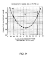
- FIG. 9 is a graph comparing cumulative divergence values of a multilayered phase difference plate according to a first embodiment and cumulative divergence values of a related-art multilayered phase difference plate;
- FIG. 10 is a main part configuration diagram of a PBS including a multilayered phase difference plate
- FIG. 11 is a main part configuration diagram of a projector including a multilayered phase difference plates
- FIG. 12 is a graph comparing cumulative divergence values of a multilayered phase difference plate according to a second embodiment and cumulative divergence values of a related-art multilayered phase difference plate;
- FIG. 13 is a graph comparing cumulative divergence values of a multilayered phase difference plate according to a third embodiment and cumulative divergence values of a related-art multilayered phase difference plate.
- F represents a phase difference
- d represents a plate thickness
- Ne represents an extraordinary ray refractive index
- No represents an ordinary ray refractive index
- ⁇ represents a wavelength
- T represents a polarization conversion efficiency
- ⁇ represents an optical axis azimuth.
- the polarization conversion efficiency is obtained for each of the selected wavelengths at intervals of 5 nm.
- the differences between the obtained polarization conversion efficiencies and the ideal value 1.00 are defined as divergence values.
- the divergence values with respect to the wavelengths in a target wavelength range are accumulated to obtain a cumulative divergence value.
- FIG. 1 is an explanatory drawing showing a multilayered phase difference plate according to a first embodiment.
- FIG. 1 is a drawing showing polarization conversion of incident light.
- FIG. 2 is a drawing showing optical axis azimuths.
- a multilayered phase difference plate 1 includes a first phase difference plate 10 and a second phase difference plate 20 .
- the first and second phase difference plates 10 and 20 are bonded together in a manner that optical axes 11 and 21 intersect each other.
- the start point is the coordinates PO as an intersection of an S 1 axis and the spherical surface.
- a rotation axis R 1 is set in a position reached by rotating the S 1 axis by 2 ⁇ a counterclockwise.
- a position reached by rotating PO by 180° clockwise with the R 1 axis used as a rotation axis is represented by P 1 .
- FIG. 4 shows a diagram of the Poincare sphere of FIG. 3 seen from an S 3 axis.
- the rotation axis R 1 used when the polarization plane is moved from the coordinates PO to the coordinates P 1 is located in a position reached by rotating the S 1 axis by 2 ⁇ a.
- the rotation axis R 2 used when the polarization plane is moved from the coordinates P 1 to the coordinates P 2 is located in a position reached by rotating the S 1 axis by 2 ⁇ b.
- FIG. 5 is a diagram linearly indicating phase differences in a case where the polarized light is moved from the coordinates PO to the coordinates P 2 on the equatorial plane of the Poincare sphere shown in FIG. 3 .
- the equatorial plane extending from the coordinates PO through the coordinates P 1 until the coordinates P 2 should be represented by a curve, it is represented as a straight line for the sake of clarity.
- rx is a turning radius in a case where the polarized light is moved from the coordinates PO to the coordinates P 1 with the R 1 axis used as the rotation axis.
- rz is a turning radius in a case where the polarized light is moved from the coordinates P 1 to the coordinates P 2 with the R 2 axis used as the rotation axis.
- the first phase difference plate is manufactured so that the polarized light is moved from the P 0 to P 1 using the turning radium r 1 on the Poincare sphere; however, if the manufacturing accuracy in thickness of the phase difference plate deviates from the designed value thereof, the polarized light cannot be moved to P 1 but is moved to P 1 x .
- the second phase difference plate is manufactured so that the polarized light is moved from the P 1 to P 2 using the turning radium rz.
- the deviation amount ⁇ b is derived from the formula below.
- ⁇ ⁇ ⁇ ⁇ ⁇ ⁇ ⁇ b cos - 1 ⁇ ( 1 - ( 1 - cos ⁇ ( 4 ⁇ ⁇ ⁇ ⁇ a ) ) ⁇ ( 1 - cos ⁇ ⁇ ⁇ ⁇ ⁇ a ) ( 1 - cos ⁇ ⁇ 4 ⁇ ( ⁇ - ⁇ ⁇ ⁇ a ) ) )
- Formula 1 is applied to a multilayered phase difference plate formed by combining and bonding together multiple phase difference plates, the multiple phase difference plates are combined so that these plates each have a phase difference ⁇ that is optimum for each other.
- the phase difference of the multilayered phase difference plate matches the target value, thereby increasing the polarization conversion efficiency most.
- the plate thicknesses of the first and second phase difference plates of the multilayered phase difference plate having the optimum phase difference obtained from Formula (1) are obtained from Formulas (2) and (3).
- the obtained plate thicknesses are represented as a graph in FIG. 6 .
- Table 1 shows the polarization conversion efficiencies of the multilayered phase difference plate formed by bonding together a phase difference plate having a first plate thickness T 1 and a phase difference plate having a second plate thickness T 2 .
- a multilayered phase difference plate preferably has a small polarization conversion efficiency loss. Specifically, it can be said that F, G, and H obtain smaller polarization conversion efficiency losses than J and K and therefore have higher polarization conversion efficiencies. In other words, a multilayered phase difference plate combined under the conditions matching the solid line shown in FIG. 7 , that is, using Formula (1), provide a higher polarization conversion efficiency.
- the multilayered phase difference plate 1 shown FIG. 1 is formed in a manner that the respective plate thicknesses of the first and second phase difference plates 10 and 20 are in the range of 23.80 ⁇ m to 31.39 ⁇ m.
- the first and second phase difference plates 10 and 20 are formed in approximately the same plate thicknesses.
- the first and second phase difference plates 10 and 20 are formed of Y-cut quartz crystal substrates having the optical axes 11 and 21 , respectively, along the plate surface.
- the optical axis azimuth ⁇ a of the first phase difference plate 10 and the optical axis azimuth ⁇ b of the second phase difference plate 20 are set according to Formulas (2) and (3), the Mueller matrix formula, and the like.
- the optical axis azimuths ⁇ a and ⁇ b represent the angles that the optical axes 11 and 12 form with vibration planes 13 and 14 horizontal to incident light, counterclockwise from the vibration planes 13 and 14 .
- the settable ranges of the optical axis azimuths ⁇ a and ⁇ b with respect to the range of the plate thicknesses of the first and second phase difference plates 10 and 20 are shown.
- Table 2 shows the settable ranges of the optical axis azimuths ⁇ a and ⁇ b with respect to the above-described three plate thicknesses of the first and second phase difference plates 10 and 20 .
- the optical axis azimuth ⁇ a is in the range of 21.7° to 23.3° and the optical axis azimuth ⁇ b is in the range of 66.7° to 68.3°.
- the optical axis azimuth ⁇ a is in the range of 12.0° to 33.0°
- the optical axis azimuth ⁇ b is in the range of 57.0° to 78.0°.
- the optical axis azimuth ⁇ a is in the range of 21.4° to 23.6° and the optical axis azimuth ⁇ b is in the range of 66.4° to 68.6°.
- the optical axis azimuth ⁇ b is a value obtained by adding a to the set value of the optical axis azimuth ⁇ a.
- the above-described optical axis azimuth ⁇ b is calculated on the assumption that the angle ⁇ formed by the optical axis azimuths ⁇ a and ⁇ b is 45°.
- the angle ⁇ formed by the optical axis azimuths ⁇ a and ⁇ b is not limited to 45° and may be set to an angle other than 45° according to the combination of the plate thickness and the optical axis azimuth ⁇ a.
- the multilayered phase difference plate 1 shown in FIG. 1 serves as a half-wavelength phase difference plate.
- linearly polarized light 30 as a p-polarization component of incident light enters the multilayered phase difference plate 1
- the phase of the linearly polarized light 30 is shifted by 180°, thereby rotating the polarization plane by 90°.
- the linearly polarized light 30 is polarization-converted into linearly polarized light 40 as an s-polarization component so that the linearly polarized light 40 goes out of the multilayered phase difference plate 1 .
- FIG. 8 is a graph used to determine the cumulative divergence value.
- the cumulative divergence value is obtained by determining the divergence values across the desired wavelength range and summing the results.
- the cumulative divergence value is represented by a rough area 56 in the graph of FIG. 8 . When the cumulative divergence value becomes smaller, the polarization conversion efficiency becomes higher.
- FIG. 9 is a graph comparing the polarization conversion efficiency of the multilayered phase difference plate according to the first embodiment and that of a related-art multilayered phase difference plate in the wavelength range of 400 nm to 700 nm using the cumulative divergence value with respect to the plate thickness of the phase difference plate.
- the cumulative divergence value is calculated on the assumption that the first and second phase difference plates are approximately the same thickness.
- the lateral axis of FIG. 9 represents the plate thickness of the phase difference plate and the vertical axis of FIG. 9 represents the cumulative divergence value.
- a curve 60 is a line obtained by linking the cumulative divergence values pursuant to the first embodiment and with respect to the plate thicknesses.
- a straight line 70 is a line obtained by plotting the cumulative divergence values of the related-art multilayered phase difference plate.
- the cumulative divergence value of the multilayered phase difference plate according to the first embodiment is smaller than that of the related-art multilayered phase difference plate.
- the cumulative divergence value of the multilayered phase difference plate 1 according to the first embodiment is smaller than that of the related-art multilayered phase difference plate when the plate thicknesses of the first and second phase difference plates 10 and 20 are in the range of 24 ⁇ m to 31 ⁇ m and therefore the polarization conversion efficiency of the multilayered phase difference plate 1 is higher than that of the related-art multilayered phase difference plate. If the first and second phase difference plates utilize this plate thickness range and are combined using Formula (1), the polarization conversion efficiency is further increased.
- the multilayered phase difference plate 1 having the above-described plate thickness obtains a higher polarization conversion efficiency than that of the related-art multilayered phase difference plate in the range of 400 nm to 700 nm. While the above-described optimization of the plate thickness range is on the assumption that the two phase plates are approximately the same, an even higher polarization conversion efficiency is obtained in the range of 400 nm to 700 nm by further optimizing the two plate thicknesses in view of Formula (1).
- FIG. 10 is a main part configuration diagram of a polarization beam splitter (hereafter referred to as a “PBS”) 2 capable of being used as a polarization conversion optical element and including the multilayered phase difference plate according to the first embodiment.
- a prism array 50 having polarization split films 52 formed on slopes of prisms 51 made of glass or the like includes the multiple multilayered phase difference plates 1 in predetermined positions on the side of outgoing light.
- the PBS 2 has the following polarization conversion function: when randomly polarized light beams enter the PBS 2 as incident light from the left side of FIG. 10 , the polarization components are directed to one direction in the PBS 2 and then go out to the right side of FIG. 10 .
- a p-polarization component of the incident light beam transmits through a polarization split film 52 according to an optical characteristic thereof and then enters the multilayered phase difference plate 1 . Then the p-polarization component is polarization-converted by the multilayered phase difference plate 1 so that the polarization plane is rotated by 90°. Thus, the p-polarization component goes out as an s-polarization component.
- an s-polarization component of an incident light beam is reflected by the polarization split film 52 toward a lower part of FIG. 10 and then reflected toward the right side by another polarization split film 52 located below the polarization split film 52 according to an optical characteristic thereof.
- the s-polarization component goes out while remaining as an s-polarization component.
- most of the randomly polarized light beams incident to the PBS 2 are polarization-converted into s-polarization components and then go out of the PBS 2 .
- FIG. 11 is a main part configuration diagram of one example of a projector including multiple light sources.
- the above-described PBS is used as a polarization conversion element 540 or a polarization conversion element 541 .
- This projector includes a lamp 501 serving as a white light source, and a reflector 511 .
- a light beam guided from this light source is dispersed or collected by a multi-lens 531 , a multi-lens 532 , and the like and then enters the polarization conversion element 540 including the above-described PBS.
- the above-described white light source is natural light in a wavelength range of approximately 400 nm to 700 nm. Therefore, by using the PBS including the multilayered phase difference plate 1 according to the first embodiment, the polarization conversion efficiency is increased, and the light beam from the light source is effectively used. As a result, a projector that provides excellent brightness is achieved.
- a light source 502 shown in FIG. 11 is a single-color light source made of a light-emitting diode.
- a light beam guided from this light source is dispersed or collected by a multi-lens 533 , a multi-lens 534 , and the like and then enters a polarization conversion element 541 including the above-described PBS.
- This single-color light source provides light beams in any one of, for example, a blue wavelength range (approximately 400 nm to 500 nm), a green wavelength range (approximately 500 nm to 600 nm), and a red wavelength range (approximately 600 nm to 700 nm).
- a blue wavelength range approximately 400 nm to 500 nm
- a green wavelength range approximately 500 nm to 600 nm
- a red wavelength range approximately 600 nm to 700 nm.
- FIG. 11 is shown for illustrative purpose only and the invention described in this application is also favorably applied to a projector including only a white light source, which is a lamp, as a light source or a projector including only single-color light sources as light sources.
- Multilayered phase difference plates according to embodiments below including a multilayered phase difference plate according to a second embodiment, differ in the plate thickness range of the first and second phase difference plates and the optical axis azimuth range thereof from the multilayered phase difference plate according to the first embodiment.
- the differences between these embodiments and the multilayered phase difference plate according to the first embodiment will be mainly described while commonly using FIGS. 1 and 2 .
- FIGS. 1 and 2 Note that the reference numerals corresponding to the similar elements as shown in the first embodiment, FIGS. 1 and 2 , are provided in parenthesis following the newly recited element numbers.
- a multilayered phase difference plate 101 ( 1 ) includes a first phase difference plate 110 ( 10 ) and a second phase difference plate 120 ( 20 ).
- the multilayered phase difference plate 101 is formed in a manner that the plate thicknesses of the first and second phase difference plates 110 and 120 are in the range of 20.73 ⁇ m to 26.34 ⁇ m.
- the first and second phase difference plates 110 and 120 are formed in approximately the same plate thicknesses.
- the first and second phase difference plates 110 and 120 of the multilayered phase difference plate 101 are formed of Y-cut quartz crystal substrates
- the optical axis azimuth ⁇ a of the first phase difference plate 110 and the optical axis azimuth ⁇ b of the second phase difference plate 120 are set according to Formulas (2) and (3), the Mueller matrix formula, and the like.
- the settable ranges of the optical axis azimuths ⁇ a and ⁇ b in the range of the plate thicknesses of the first and second phase difference plates 110 and 120 are shown.
- Table 3 shows the settable ranges of the optical axis azimuths ⁇ a and ⁇ b with respect to the above-described three plate thicknesses of the first and second phase difference plates 110 and 120 .
- the optical axis azimuth ⁇ a is in the range of 21.4° to 23.6° and the optical axis azimuth ⁇ b is in the range of 66.4° to 68.6°.
- the optical axis azimuth ⁇ a is in the range of 11.5° to 33.5° and the optical axis azimuth ⁇ b is in the range of 56.5° to 78.5°.
- the optical axis azimuth ⁇ a is in the range of 21.3° to 23.7° and the optical axis azimuth ⁇ b is in the range of 66.3° to 68.7°.
- the optical axis azimuth ⁇ b is a value obtained by adding a to the set value of the optical axis azimuth ⁇ a.
- the angle ⁇ formed by the optical axis azimuths ⁇ a and ⁇ b is not limited to 45° and may be set to an angle other than 45° according to the combination of the plate thickness and the optical axis azimuth ⁇ a.
- the multilayered phase difference plate 101 serves as a half-wavelength phase difference plate.
- the phase of the linearly polarized light 30 is shifted by 180°, thereby rotating the polarization plane by 90°.
- the linearly polarized light 30 is polarization-converted into the linearly polarized light 40 as an s-polarization component so that the linearly polarized light 40 goes out of the multilayered phase difference plate 101 .
- FIG. 12 A result of a comparison between the efficiency of polarization conversion from the p-polarization component to the s-polarization component performed by the multilayered phase difference plate 101 and that of a related-art multilayered phase difference plate is shown in FIG. 12 .
- FIG. 12 is a graph comparing the polarization conversion efficiency of the multilayered phase difference plate 101 and that of the related-art multilayered phase difference plate in the wavelength range of 400 nm to 500 nm using the cumulative divergence value with respect to each plate thickness.
- a curve 160 is a line obtained by linking the cumulative divergence values with respect to the plate thicknesses of the multilayered phase difference plate 101 .
- a straight line 170 is a line obtained by plotting the cumulative divergence values of the related-art multilayered phase difference plate.
- the cumulative divergence value of the multilayered phase difference plate 101 according to the second embodiment is smaller than that of the related-art multilayered phase difference plate when the respective plate thicknesses of the first and second phase difference plates 110 and 120 are in the range of 21 ⁇ m to 26 ⁇ m and therefore the multilayered phase difference plate 101 obtains a higher polarization conversion efficiency than that of the related-art multilayered phase difference plate.
- the multilayered phase difference plate 101 obtains a higher polarization conversion efficiency in the range of 400 nm to 500 nm than that of the related-art multilayered phase difference plate. While the above-described optimization of the plate thickness range is on the assumption that the two phase plates are approximately the same, an even higher polarization conversion efficiency is obtained in the range of 400 nm to 500 nm by further optimizing the two plate thicknesses in view of Formula (1).
- the multilayered phase difference plate 101 according to the second embodiment is used in an optical element such as a PBS, like in the exemplary discussion regarding the multilayered phase difference plate 1 according to the first embodiment, and if incident light is in a blue wavelength range (approximately 400 nm to 500 nm), the polarization conversion efficiency is favorably increased.
- a multilayered phase difference plate 201 ( 1 ) includes a first phase difference plate 210 ( 10 ) and a second phase difference plate 220 ( 20 ).
- the multilayered phase difference plate 201 is formed in a manner that the plate thicknesses of the first and second phase difference plates 210 and 220 are in the range of 24.04 ⁇ m to 35.28 ⁇ m.
- the first and second phase difference plates 210 and 220 are formed in approximately the same plate thicknesses.
- the first and second phase difference plates 210 and 220 of the multilayered phase difference plate 201 are formed of Y-cut quartz crystal substrates.
- the optical axis azimuth ⁇ a of the first phase difference plate 210 and the optical axis azimuth ⁇ b of the second phase difference plate 220 are set according to Formulas (2) and (3), the Mueller matrix formula, and the like.
- the settable ranges of the optical axis azimuths ⁇ a and ⁇ b in the range of the plate thicknesses of the first and second phase difference plates 210 and 220 are shown.
- Table 4 shows the settable ranges of the optical axis azimuths ⁇ a and ⁇ b with respect to the above-described three plate thicknesses of the first and second phase difference plates 210 and 220 .
- the optical axis azimuth ⁇ a is in the range of 21.2° to 23.8°
- the optical axis azimuth ⁇ b is in the range of 66.2° to 68.8°.
- the optical axis azimuth ⁇ a is in the range of ⁇ 4.2° to 49.2° and the optical axis azimuth ⁇ b is in the range of 40.8° to 94.2°.
- the optical axis azimuth ⁇ a is in the range of 22.2° to 22.8° and the optical axis azimuth ⁇ b is in the range of 67.2° to 67.8°.
- optical axis azimuth ⁇ b is calculated on the assumption that the angle ⁇ formed by the optical axis azimuths ⁇ a and ⁇ b is 45°.
- the optical axis azimuth ⁇ b is a value obtained by adding 45° to the set value of the optical axis azimuth ⁇ a.
- the angle ⁇ formed by the optical axis azimuths ⁇ a and ⁇ b is not limited to 45° and may be set to an angle other than 45° according to the combination of the plate thickness and the optical axis azimuth ⁇ a.
- the multilayered phase difference plate 201 serves as a half-wavelength phase difference plate.
- the phase of the linearly polarized light 30 is shifted by 180°, thereby rotating the polarization plane by 90°.
- the linearly polarized light 30 is polarization-converted into the linearly polarized light 40 as an s-polarization component so that the linearly polarized light 40 goes out of the multilayered phase difference plate 201 .
- FIG. 13 A result of a comparison between the efficiency of polarization conversion from the p-polarization component to the s-polarization component performed by the multilayered phase difference plate 201 and that of the related-art multilayered phase difference plate is shown in FIG. 13 .
- FIG. 13 is a graph comparing the polarization conversion efficiency of the multilayered phase difference plate 201 and that of the related-art multilayered phase difference plate in the wavelength range of 500 nm to 600 nm using the cumulative divergence value with respect to each plate thickness.
- a curve 260 is a line obtained by linking the cumulative divergence values with respect to the plate thicknesses of the multilayered phase difference plate 201 .
- a straight line 270 is a line obtained by plotting the cumulative divergence values of the related-art multilayered phase difference plate.
- the cumulative divergence value of the multilayered phase difference plate 201 according to the third embodiment is smaller than that of the related-art multilayered phase difference plate when the respective plate thicknesses of the first and second phase difference plates 210 and 220 are in the range of 25 ⁇ m to 35 ⁇ m and therefore the multilayered phase difference plate 201 obtains a higher polarization conversion efficiency than that of the related-art multilayered phase difference plate.
- the multilayered phase difference plate 201 obtains a higher polarization conversion efficiency in the range of 500 nm to 600 nm than that of the related-art multilayered phase difference plate. While the above-described optimization of the plate thickness range is on the assumption that the two phase plates are approximately the same, an even higher polarization conversion efficiency is obtained in the range of 500 nm to 600 nm by further optimizing the two plate thicknesses in view of Formula (1).
- the multilayered phase difference plate 201 according to the third embodiment is used in an optical element such as a PBS, like in the exemplary discussion regarding the multilayered phase difference plate 1 according to the first embodiment, and if incident light is in a green wavelength range (approximately 500 nm to 600 nm), the polarization conversion efficiency is favorably increased.
- a multilayered phase difference plate 301 ( 1 ) includes a first phase difference plate 310 ( 10 ) and a second phase difference plate 320 ( 20 ).
- the multilayered phase difference plate 301 is formed in a manner that the plate thicknesses of the first and second phase difference plates 310 and 320 are in the range of 23.98 ⁇ m to 47.41 ⁇ m.
- the first and second phase difference plates 310 and 320 are formed in approximately the same plate thicknesses.
- the first and second phase difference plates 310 and 320 of the multilayered phase difference plate 301 are formed of Y-cut quartz crystal substrates
- the optical axis azimuth ⁇ a of the first phase difference plate 310 and the optical axis azimuth ⁇ b of the second phase difference plate 320 are set according to Formulas (2) and (3), the Mueller matrix formula, and the like.
- the settable ranges of the optical axis azimuths ⁇ a and ⁇ b in the range of the plate thicknesses of the first and second phase difference plates 310 and 320 are shown.
- Table 5 shows the settable ranges of the optical axis azimuths ⁇ a and ⁇ b with respect to the above-described three plate thicknesses of the first and second phase difference plates 310 and 320 .
- the optical axis azimuth ⁇ a is in the range of 21.1° to 23.9° and the optical axis azimuth ⁇ b is in the range of 66.1° to 68.9°.
- the optical axis azimuth ⁇ a is in the range of 0.0° to 180.0° and the optical axis azimuth ⁇ b is in the range of 45.0° to 225.0°.
- the optical axis azimuth ⁇ a is in the range of 21.1° to 23.9° and the optical axis azimuth ⁇ b is in the range of 66.1° to 68.9°.
- optical axis azimuth ⁇ b is calculated on the assumption that the angle ⁇ formed by the optical axis azimuths ⁇ a and ⁇ b is 45°.
- the optical axis azimuth ⁇ b is a value obtained by adding 45° to the set value of the optical axis azimuth ⁇ a.
- the angle ⁇ formed by the optical axis azimuths ⁇ a and ⁇ b is not limited to 45° and may be set to an angle other than 45° according to the combination of the plate thickness and the optical axis azimuth ⁇ a.
- the multilayered phase difference plate 301 serves as a half-wavelength phase difference plate.
- the phase of the linearly polarized light 30 is shifted by 180°, thereby rotating the polarization plane by 90°.
- the linearly polarized light 30 is polarization-converted into the linearly polarized light 40 as an s-polarization component so that the linearly polarized light 40 goes out of the multilayered phase difference plate 301 .
- FIG. 14 A result of a comparison between the efficiency of polarization conversion from the p-polarization component to the s-polarization component performed by the multilayered phase difference plate 301 and that of the related-art multilayered phase difference plate is shown in FIG. 14 .
- FIG. 14 is a graph comparing the polarization conversion efficiency of the multilayered phase difference plate 301 and that of the related-art multilayered phase difference plate in the wavelength range of 600 nm to 700 nm using the cumulative divergence value with respect to each plate thickness.
- a curve 360 is a line obtained by linking the cumulative divergence values with respect to the plate thicknesses of the multilayered phase difference plate 301 .
- a straight line 370 is a line obtained by plotting the cumulative divergence values of the related-art multilayered phase difference plate.
- the cumulative divergence value of the multilayered phase difference plate 301 according to the fourth embodiment is smaller than that of the related-art multilayered phase difference plate when the respective plate thicknesses of the first and second phase difference plates 310 and 320 are in the range of 24 ⁇ m to 47 ⁇ m and therefore the multilayered phase difference plate 301 obtains a higher polarization conversion efficiency than that of the related-art multilayered phase difference plate.
- the multilayered phase difference plate 301 obtains a higher polarization conversion efficiency in the range of 600 nm to 700 nm than that of the related-art multilayered phase difference plate. While the above-described optimization of the plate thickness range is on the assumption that the two phase plates are approximately the same, an even higher polarization conversion efficiency is obtained in the range of 600 nm to 700 nm by further optimizing the two plate thicknesses in view of Formula (1).
- the multilayered phase difference plate 301 according to the fourth embodiment is used in an optical element such as a PBS, like in the exemplary discussion regarding the multilayered phase difference plate 1 according to the first embodiment, and if incident light is in a red wavelength range (approximately 600 nm to 700 nm), the polarization conversion efficiency is favorably increased.
- these multilayered phase difference plates may be used as a phase plate 572 , a phase plate 573 , or the like provided in the proximity of a cross prism 590 shown in FIG. 11 .
Landscapes
- Physics & Mathematics (AREA)
- General Physics & Mathematics (AREA)
- Optics & Photonics (AREA)
- Projection Apparatus (AREA)
- Polarising Elements (AREA)
Abstract
Description
Γ=2πd(Ne−No)/λ Formula (2)
T=4(sin2 θ)(cos2 θ)(sin2 Γ/2) Formula (3)
θb=θa+α Formula (4)
40°<α<50° Formula (5)
∠P0-O-P1=4θa Formula (6)
∠P1-O-P2=4α−4θa Formula (7)
L=2(rx)2(1−cos ΔΓa) Formula (8)
L=2(rz)2(1−cos ΔΓb) Formula (9)
2(rx)2(1−cos ΔΓa)=2(rz)2(1−cos ΔΓb) Formula (10)
(2rx)2=2k 2−2k 2 cos 4θa
2(rx)2 =k 2 −k 2 cos 4θa Formula (11)
(2rz)2=2k 2−2k 2 cos 4(α−θa)
2(rz)2 =k 2 −k 2 cos 4(α−θa) Formula (12)
(k 2 −k 2 cos 4θa)(1−cos ΔΓa)=(k 2 −k 2 cos 4(α−θa))(1−cos ΔΓb)
(1−cos 4θb)(1−cos ΔΓa)=(1−cos 4(α−θa))(1−cos ΔΓb)
1−cos ΔΓb=(1−cos 4θa)(1−cos ΔΓa)/(1−cos 4(α−θa))
| TABLE 1 | ||||
| Polarization conversion | ||||
| T2 (μm) | T1 (μm) | efficiency loss | ||
| F | 28.2 | 28.2 | 1.3% | ||
| G | 29.8 | 30.2 | 1.8% | ||
| H | 25.1 | 24.2 | 2.3% | ||
| J | 29.8 | 32.9 | 3.6% | ||
| K | 28.2 | 24.2 | 3.2% | ||
| TABLE 2 | ||
| Plate thickness (μm) | θa(°) | θb(°) |
| 23.80 | 21.7 to 23.3 | 66.7 to 68.3 |
| 27.73 | 12.0 to 33.0 | 57.0 to 78.0 |
| 31.39 | 21.4 to 23.6 | 66.4 to 68.6 |
| TABLE 3 | ||
| Plate thickness (μm) | θa(°) | θb(°) |
| 20.73 | 21.4 to 23.6 | 66.4 to 68.6 |
| 23.61 | 11.5 to 33.5 | 56.5 to 78.5 |
| 26.34 | 21.3 to 23.7 | 66.3 to 68.7 |
| TABLE 4 | ||
| Plate thickness (μm) | θa(°) | θb(°) |
| 24.04 | 21.2 to 23.8 | 66.2 to 68.8 |
| 29.77 | −4.2 to 49.2 | 40.8 to 94.2 |
| 35.28 | 22.2 to 22.8 | 67.2 to 67.8 |
| TABLE 5 | ||
| Plate thickness (μm) | θa(°) | θb(°) |
| 23.98 | 21.1 to 23.9 | 66.1 to 68.9 |
| 35.76 | 0.0 to 180.0 | 45.0 to 225.0 |
| 47.41 | 21.1 to 23.9 | 66.1 to 68.9 |
Claims (19)
Applications Claiming Priority (4)
| Application Number | Priority Date | Filing Date | Title |
|---|---|---|---|
| JP2007-080844 | 2007-03-27 | ||
| JP2007080844 | 2007-03-27 | ||
| JP2008-054444 | 2008-03-05 | ||
| JP2008054444A JP4557022B2 (en) | 2007-03-27 | 2008-03-05 | Laminated phase difference plate, projection type image device |
Publications (2)
| Publication Number | Publication Date |
|---|---|
| US20080239487A1 US20080239487A1 (en) | 2008-10-02 |
| US7855834B2 true US7855834B2 (en) | 2010-12-21 |
Family
ID=39793837
Family Applications (1)
| Application Number | Title | Priority Date | Filing Date |
|---|---|---|---|
| US12/051,339 Expired - Fee Related US7855834B2 (en) | 2007-03-27 | 2008-03-19 | Multilayered phase difference plate and projector |
Country Status (1)
| Country | Link |
|---|---|
| US (1) | US7855834B2 (en) |
Cited By (2)
| Publication number | Priority date | Publication date | Assignee | Title |
|---|---|---|---|---|
| US20100110543A1 (en) * | 2008-10-31 | 2010-05-06 | Epson Toyocom Corporation | Laminated quarter wave plate |
| US20110102746A1 (en) * | 2009-11-02 | 2011-05-05 | Seiko Epson Corporation | Half-wave plate, optical pickup device, polarization conversion element, and projection display device |
Families Citing this family (4)
| Publication number | Priority date | Publication date | Assignee | Title |
|---|---|---|---|---|
| JP5251671B2 (en) * | 2009-03-30 | 2013-07-31 | セイコーエプソン株式会社 | Laminated half-wave plate, optical pickup device, polarization conversion element, and projection display device |
| JP5251672B2 (en) * | 2009-03-30 | 2013-07-31 | セイコーエプソン株式会社 | Laminated half-wave plate, optical pickup device, polarization conversion element, and projection display device |
| US8224136B2 (en) * | 2010-04-01 | 2012-07-17 | Furukawa Electric Co., Ltd. | Optical multiplexer/demultiplexer module and prism using for the same |
| US20120307361A1 (en) * | 2011-03-15 | 2012-12-06 | Ruopeng Liu | Polarization converter made of meta material |
Citations (6)
| Publication number | Priority date | Publication date | Assignee | Title |
|---|---|---|---|---|
| JP2004170853A (en) | 2002-11-22 | 2004-06-17 | Toyo Commun Equip Co Ltd | Laminated wave plate |
| US6856304B1 (en) * | 1998-01-21 | 2005-02-15 | Semiconductor Energy Laboratory Co., Ltd. | Liquid crystal projector |
| JP2006201302A (en) | 2005-01-18 | 2006-08-03 | Epson Toyocom Corp | Ultra-thin wave plate, composite optical element and optical pickup device |
| JP2006330282A (en) | 2005-05-25 | 2006-12-07 | Sony Corp | Image projection apparatus and image projection method |
| US20080100759A1 (en) * | 2006-10-27 | 2008-05-01 | Seiko Epson Corporation | Projector, optical compensation method therefor, and liquid crystal device |
| US7618715B2 (en) * | 2003-12-01 | 2009-11-17 | Jsr Corporation | Wavelength plate |
-
2008
- 2008-03-19 US US12/051,339 patent/US7855834B2/en not_active Expired - Fee Related
Patent Citations (6)
| Publication number | Priority date | Publication date | Assignee | Title |
|---|---|---|---|---|
| US6856304B1 (en) * | 1998-01-21 | 2005-02-15 | Semiconductor Energy Laboratory Co., Ltd. | Liquid crystal projector |
| JP2004170853A (en) | 2002-11-22 | 2004-06-17 | Toyo Commun Equip Co Ltd | Laminated wave plate |
| US7618715B2 (en) * | 2003-12-01 | 2009-11-17 | Jsr Corporation | Wavelength plate |
| JP2006201302A (en) | 2005-01-18 | 2006-08-03 | Epson Toyocom Corp | Ultra-thin wave plate, composite optical element and optical pickup device |
| JP2006330282A (en) | 2005-05-25 | 2006-12-07 | Sony Corp | Image projection apparatus and image projection method |
| US20080100759A1 (en) * | 2006-10-27 | 2008-05-01 | Seiko Epson Corporation | Projector, optical compensation method therefor, and liquid crystal device |
Cited By (3)
| Publication number | Priority date | Publication date | Assignee | Title |
|---|---|---|---|---|
| US20100110543A1 (en) * | 2008-10-31 | 2010-05-06 | Epson Toyocom Corporation | Laminated quarter wave plate |
| US20110102746A1 (en) * | 2009-11-02 | 2011-05-05 | Seiko Epson Corporation | Half-wave plate, optical pickup device, polarization conversion element, and projection display device |
| US8398241B2 (en) * | 2009-11-02 | 2013-03-19 | Seiko Epson Corporation | Half-wave plate, optical pickup device, polarization conversion element, and projection display device |
Also Published As
| Publication number | Publication date |
|---|---|
| US20080239487A1 (en) | 2008-10-02 |
Similar Documents
| Publication | Publication Date | Title |
|---|---|---|
| US9235111B2 (en) | Projection display apparatus | |
| US6394607B1 (en) | Polarized light separation device, method of fabricating the same and projection display apparatus using the polarized light separation device | |
| US7553025B2 (en) | Projection type image display apparatus, and optical unit and polarization splitting unit each used for the apparatus | |
| US8764197B2 (en) | Polarization conversion element, polarization converting unit, and projecting apparatus | |
| US7855834B2 (en) | Multilayered phase difference plate and projector | |
| US20090086112A1 (en) | Projection type liquid crystal display and compensation plate | |
| US7562984B2 (en) | Polarizing beam splitter and projection apparatus having the same | |
| US8201946B2 (en) | Projection image display apparatus and polarization converter with optimally aligned phase difference plates | |
| US6991334B2 (en) | Polarization beam splitting optical system | |
| JP2013250561A (en) | Projection type video display device | |
| JP2010231135A (en) | Laminated half-wave plate, optical pickup device, polarization conversion element, and projection display device | |
| US6942345B2 (en) | Projection type image display apparatus and image display system | |
| US20120081622A1 (en) | Wave plate and polarization conversion element, illumination optical system, and image display device that use wave plate | |
| JP4557022B2 (en) | Laminated phase difference plate, projection type image device | |
| US8866977B2 (en) | Projector | |
| JPH05181135A (en) | Polarizing illuminating device and projection display device using it | |
| US8643793B2 (en) | Projector | |
| US20050041165A1 (en) | Image display apparatus | |
| US7198371B2 (en) | Image displaying apparatus | |
| US8562138B2 (en) | Projection display device | |
| US20240192579A1 (en) | Wavelength selective phase difference element and projection display apparatus | |
| JP2009103863A (en) | Retardation plate and projector | |
| US20050275807A1 (en) | Color combining optical system and image projection apparatus | |
| TW200537136A (en) | Projection type image display apparatus and optical system | |
| JP5109762B2 (en) | Laminated retardation plate, polarization conversion element, and projection type image device |
Legal Events
| Date | Code | Title | Description |
|---|---|---|---|
| AS | Assignment |
Owner name: EPSON TOYOCOM CORPORATION, JAPAN Free format text: ASSIGNMENT OF ASSIGNORS INTEREST;ASSIGNORS:KOBAYASHI, SHUHO;OTO, MASAYUKI;MATSUMOTO, HIROSHI;REEL/FRAME:021078/0124;SIGNING DATES FROM 20080509 TO 20080515 Owner name: EPSON TOYOCOM CORPORATION, JAPAN Free format text: ASSIGNMENT OF ASSIGNORS INTEREST;ASSIGNORS:KOBAYASHI, SHUHO;OTO, MASAYUKI;MATSUMOTO, HIROSHI;SIGNING DATES FROM 20080509 TO 20080515;REEL/FRAME:021078/0124 |
|
| FEPP | Fee payment procedure |
Free format text: PAYOR NUMBER ASSIGNED (ORIGINAL EVENT CODE: ASPN); ENTITY STATUS OF PATENT OWNER: LARGE ENTITY |
|
| AS | Assignment |
Owner name: SEIKO EPSON CORPORATION, JAPAN Free format text: ASSIGNMENT OF ASSIGNORS INTEREST;ASSIGNOR:EPSON TOYOCOM CORPORATION;REEL/FRAME:026717/0436 Effective date: 20110725 |
|
| FPAY | Fee payment |
Year of fee payment: 4 |
|
| FEPP | Fee payment procedure |
Free format text: MAINTENANCE FEE REMINDER MAILED (ORIGINAL EVENT CODE: REM.) |
|
| LAPS | Lapse for failure to pay maintenance fees |
Free format text: PATENT EXPIRED FOR FAILURE TO PAY MAINTENANCE FEES (ORIGINAL EVENT CODE: EXP.); ENTITY STATUS OF PATENT OWNER: LARGE ENTITY |
|
| STCH | Information on status: patent discontinuation |
Free format text: PATENT EXPIRED DUE TO NONPAYMENT OF MAINTENANCE FEES UNDER 37 CFR 1.362 |
|
| FP | Lapsed due to failure to pay maintenance fee |
Effective date: 20181221 |