JP5109762B2 - Laminated retardation plate, polarization conversion element, and projection type image device - Google Patents
Laminated retardation plate, polarization conversion element, and projection type image device Download PDFInfo
- Publication number
- JP5109762B2 JP5109762B2 JP2008089918A JP2008089918A JP5109762B2 JP 5109762 B2 JP5109762 B2 JP 5109762B2 JP 2008089918 A JP2008089918 A JP 2008089918A JP 2008089918 A JP2008089918 A JP 2008089918A JP 5109762 B2 JP5109762 B2 JP 5109762B2
- Authority
- JP
- Japan
- Prior art keywords
- light
- plate
- incident
- polarization conversion
- optical axis
- Prior art date
- Legal status (The legal status is an assumption and is not a legal conclusion. Google has not performed a legal analysis and makes no representation as to the accuracy of the status listed.)
- Active
Links
Images


Description
本発明は、積層位相差板、入射される光を偏光光に変換する偏光変換素子、及び投射型映像装置に関する。The present invention relates to a laminated phase difference plate, a polarization conversion element that converts incident light into polarized light, and a projection type video apparatus.
従来、複数の透光基材と、偏光分離変換層と、反射膜とで構成された偏光変換素子が知
られている(特許文献1)。
この偏光変換素子は、1/2波長板として機能する水晶板として、積層された第1水晶
板および第2水晶板により構成されたものを適用している。そして、入射面内にあり、か
つ水晶板中を伝播する光の進行方向に直交する方向をXとしたときに、第1水晶板のX方
向に対する光学軸方位角が17.5°〜27.5°となり、第2水晶板のX方向に対する
光学軸方位角が62.5°〜72.5°となるように、第1,第2水晶板を設けている。
Conventionally, a polarization conversion element including a plurality of translucent base materials, a polarization separation conversion layer, and a reflection film is known (Patent Document 1).
In this polarization conversion element, a crystal plate functioning as a half-wave plate is applied which is constituted by a laminated first crystal plate and second crystal plate. The optical axis azimuth with respect to the X direction of the first quartz plate is 17.5 ° to 27. 27, where X is the direction that is in the incident plane and orthogonal to the traveling direction of the light propagating in the quartz plate. The first and second crystal plates are provided so that the optical axis azimuth angle with respect to the X direction of the second crystal plate is 62.5 ° to 72.5 °.
ところで、偏光変換素子の1/2波長板は、十分な偏光変換効率を有し、例えばプロジ
ェクタに利用可能な実用性を備えている必要がある。この偏光変換効率とは、例えばP偏
光成分からS偏光成分に偏光する場合に変換される割合を示し、P偏光成分が全てS偏光
成分に偏光されたとすると、理想値の1.00として示される。この偏光変換効率が理想
値1.00に近いほど、1/2波長板を通過した光量の損失が少なく、明るい映像を投射
可能な液晶プロジェクタを生産するのに好適である。
特許文献1で示される従来例では、板厚の設定により偏光変換効率を優れたものにする
構成が開示されておらず、偏光変換効率が最も優れたものとなっていないおそれがある。
By the way, the half-wave plate of the polarization conversion element needs to have sufficient polarization conversion efficiency and be practical, for example, usable for a projector. This polarization conversion efficiency indicates, for example, the rate of conversion when polarized from the P-polarized component to the S-polarized component. If all the P-polarized components are polarized to the S-polarized component, it is shown as an ideal value of 1.00. . The closer the polarization conversion efficiency is to the ideal value of 1.00, the smaller the loss of the amount of light that has passed through the half-wave plate, and the better the production of a liquid crystal projector that can project a bright image.
In the conventional example shown in
本発明の目的は、偏光変換効率が優れ、実用性を有する積層位相差板、偏光変換素子及び投射型映像装置を提供することである。 An object of the present invention is to provide a laminated phase difference plate, a polarization conversion element, and a projection type video apparatus which have excellent polarization conversion efficiency and have practicality.
本発明は、上述の課題の少なくとも一部を解決するためになされたものであり、以下の形態または適用例として実現することが可能である。
本発明の第1の形態に係る積層位相差板は、入射面の法線に対して45°の方向から入射する波長λの光に対して位相差Γ’aの第1位相差板と位相差Γ’bの第2位相差板とを各々の光学軸が交差するように積層してなり、波長λ1〜λ2(但し、λ1<λ<λ2)の範囲において前記入射面の法線に対して45°の方向から入射する直線偏光の偏光面を90deg回転させた直線偏光に変換して出射する積層位相差板であって、前記第1位相差板に入射する直線偏光の振動面を前記入射面に投影した投影振動面と前記第1位相差板の第1結晶光学軸とのなす角度を第1光学軸方位角θaaとし、前記投影振動面と前記第2位相差板の第2結晶光学軸とのなす角度を第2光学軸方位角θbbとし、前記入射する直線偏光の光軸に垂直な面に前記第1結晶光学軸を投影した第1投影結晶光学軸と前記入射する直線偏光の振動面とのなす角度を第1投影光学軸方位角θaとし、前記垂直な面に前記第2結晶光学軸を投影した第2投影結晶光学軸と前記入射する直線偏光の振動面とのなす角度を第2投影光学軸方位角θbとしたとき、前記第1光学軸方位角θaaと前記第1投影光学軸方位角θaとの関係は、
θaa=Atan(tan(θa)/21/2)を満足し、
前記第2光学軸方位角θbbと前記第2投影光学軸方位角θbとの関係は、
θbb=Atan(tan(θb)/21/2)を満足し、
前記入射する直線偏光の光軸を前記入射面に投射したときの投射像と前記投影振動面とのなす角度を光線進行角度θ5とし、前記入射面の法線に対して45°の方向と、前記入射する直線偏光の光軸とのなす角度を入射角度θ6としたき、前記光線進行角度θ5と前記入射角度θ6は、θ5=0°、−10°≦θ6≦+10° を満足し、
前記第1投影光学軸方位角θaと前記第2投影光学軸方位角θbとの関係が、設定値をαとすると、 θb=θa+α 40°<α<50° の条件を満足し、
前記位相差Γ’aと前記位相差Γ’bは、前記第1水晶板の位相差Γaの設計目標値からのずれ量をΔΓaとし、前記第2水晶板の位相差Γbの設計目標値からのずれ量をΔΓbとすると、
Γ’a=Γa+ΔΓa、 Γ’b=Γb+ΔΓb、 Γa=180°、Γb=180°
を満足し、
前記ΔΓaと前記ΔΓbとの関係が、式(1)を満足することを特徴とする。

本発明の第3の形態に係る積層位相差板は、λ1=400nm、λ2=700nmとしたときに、前記第1位相差板の厚みd1が21.2μm〜50.0μmの範囲であり、前記第2位相差板の厚みd2が13.5μm〜31.9μmの範囲であることを特徴とする。
本発明の第4の形態に係る積層位相差板は、λ1=400nm、λ2=500nmとしたときに、前記第1位相差板の厚みd1が16.8μm〜43.7μmの範囲であり、前記第2位相差板の厚みd2が10.7μm〜27.8μmの範囲であることを特徴とする。
本発明の第5の形態に係る積層位相差板は、λ1=500nm、λ2=600nmとしたときに、前記第1位相差板の厚みd1が21.0μm〜55.6μmの範囲であり、
前記第2位相差板の厚みd2が13.4μm〜35.4μmの範囲であることを特徴とする。
本発明の第6の形態に係る積層位相差板は、λ1=600nm、λ2=700nmとしたときに、前記第1位相差板の厚みd1が25.3μm〜67.2μmの範囲であり、前記第2位相差板の厚みd2が16.1μm〜42.8μmの範囲であることを特徴とする。
本発明の第7の形態に係る偏光変換素子は、第1の主面を光入射面としかつ第2の主面を光出射面とする平板状の積層プリズムと、前記第1及び第2の主面に対し45°傾斜して間隔をおいて交互に平行配置された偏光分離変換層と反射部とを備え、前記偏光分離変換層は、前記第1の主面側から順に配置された偏光分離部と当該偏光分離部の光出射面側に設けられた波長板とからなり、前記偏光分離部は、前記第1の主面側から入射した光を互いに直交する第1の直線偏光と第2の直線偏光とに分離し、前記第1の直線偏光を透過させかつ前記第2の直線偏光を反射し、前記波長板は、前記偏光分離部を透過した前記第1の直線偏光の振動面を90°回転させることにより前記第2の直線偏光の振動面と平行な振動面を有する直線偏光に変換して出射させ、前記波長板が、前述の構成の積層位相差板であることを特徴とする。
本発明の第8の形態に係る投射型映像装置は、光源と、前記光源からの光を前記第2の直線偏光に変換して出射する偏光変換素子と、前記偏光変換素子からの出射光を、画像情報に応じて変調する変調手段と、前記変調手段により変調された光を投写する投写光学系と、を有し、前記偏光変換素子が前述の偏光変換素子であることを特徴とする。
本発明の第9の形態に係る投射型映像装置は、前記変調手段が液晶パネルであることを特徴とする。
本発明の第10の形態に係る投射型映像装置は、光源と、前記光源からの光を前記第2の直線偏光に変換して出射する偏光変換素子と、前記偏光変換素子からの出射光を、画像情報に応じて変調する変調手段と、前記変調手段により変調された光を投写する投写光学系と、を有する投射型映像装置であって、前述の積層位相差板を有することを特徴とする。
[適用例1]
本適用例に係わる偏光変換素子は、光入射面を有し一連に接合された複数の透光基材と、隣接する一対の前記透光基材の第1接合部分に沿って前記光入射面に対して45°傾斜した状態で挟み込まれた偏光分離変換層と、前記第1接合部分に隣り合う第2接合部分に沿って前記偏光分離変換層と略平行となる状態で挟み込まれた反射膜と、を備え、−10°〜+10°の入射角度で前記光入射面に入射される光を偏光光に変換して射出する偏光変換素子であって、前記偏光分離変換層は、入射される光を2個の偏光成分に分離して一方の偏光成分を透過させるとともに他方の偏光成分を反射させる偏光分離膜と、この偏光分離膜に対して前記光入射面と反対側に配置され前記偏光分離膜を透過した前記一方の偏光成分を他方の偏光成分に変換して透過させる1/2波長板と、を備え、この1/2波長板は、水晶からYカットで切り出した水晶により板状に形成された第1水晶板および第2水晶板を積層して構成され、前記第1水晶板は、板厚が21.2μm〜50.0μmであり、光学軸方位が前記一方の偏光成分の振動面に対してθaa°回転した方向となる状態で設けられ、前記第2水晶板は、板厚が13.5μm〜31.9μmであり、光学軸方位が前記一方の偏光成分の振動面に対してθbb°回転した方向となる状態で設けられ、前記第1水晶板の位相差Γaと、前記第1水晶板の位相差Γaのずれ量ΔΓaと、前記第2水晶板の位相差Γbと、前記第2水晶板の位相差Γbのずれ量ΔΓbと、が式(1)を満たすことを特徴とする。
SUMMARY An advantage of some aspects of the invention is to solve at least a part of the problems described above, and the invention can be implemented as the following forms or application examples.
The laminated phase difference plate according to the first aspect of the present invention is different from the first phase difference plate having the phase difference Γ′a with respect to the light having the wavelength λ incident from the direction of 45 ° with respect to the normal line of the incident surface. A second retardation plate having a phase difference Γ′b is laminated so that the optical axes intersect with each other, and is in a wavelength range of λ1 to λ2 (where λ1 <λ <λ2) with respect to the normal line of the incident surface. The polarization plane of the linearly polarized light incident from the direction of 45 ° is converted into the linearly polarized light rotated by 90 degrees and emitted, and the vibrating surface of the linearly polarized light incident on the first retardation plate is An angle formed between the projection vibration surface projected onto the incident surface and the first crystal optical axis of the first retardation plate is defined as a first optical axis azimuth angle θaa, and the projection vibration surface and the second crystal of the second retardation plate are included. An angle formed with the optical axis is a second optical axis azimuth angle θbb, and the first connection is made on a plane perpendicular to the optical axis of the incident linearly polarized light. An angle formed by the first projected crystal optical axis projected from the optical axis and the incident plane of the linearly polarized light is defined as a first projected optical axis azimuth angle θa, and the second crystal optical axis projected onto the perpendicular plane. When the angle formed between the two projection crystal optical axes and the vibration plane of the incident linearly polarized light is the second projection optical axis azimuth angle θb, the first optical axis azimuth angle θaa and the first projection optical axis azimuth angle θa The relationship
θaa = Atan (tan (θa) / 2 1/2 ) is satisfied,
The relationship between the second optical axis azimuth angle θbb and the second projection optical axis azimuth angle θb is
θbb = Atan (tan (θb) / 2 1/2 ) is satisfied,
The angle formed between the projection image when the optical axis of the incident linearly polarized light is projected onto the incident surface and the projection vibration surface is a light beam traveling angle θ5, and a direction of 45 ° with respect to the normal of the incident surface, The angle formed by the optical axis of the incident linearly polarized light is defined as an incident angle θ6, and the light ray traveling angle θ5 and the incident angle θ6 satisfy θ5 = 0 °, −10 ° ≦ θ6 ≦ + 10 °,
The relationship between the first projection optical axis azimuth angle θa and the second projection optical axis azimuth angle θb satisfies the condition of θb = θa +
The phase difference Γ′a and the phase difference Γ′b are set as ΔΓa as a deviation amount from the design target value of the phase difference Γa of the first crystal plate, and from the design target value of the phase difference Γb of the second crystal plate. If the amount of deviation is ΔΓb,
Γ′a = Γa + ΔΓa, Γ′b = Γb + ΔΓb, Γa = 180 °, Γb = 180 °
Satisfied,
The relationship between ΔΓa and ΔΓb satisfies the formula (1).
In the laminated retardation plate according to the third aspect of the present invention, when λ1 = 400 nm and λ2 = 700 nm, the thickness d1 of the first retardation plate is in the range of 21.2 μm to 50.0 μm, The thickness d2 of the second retardation plate is in the range of 13.5 μm to 31.9 μm.
In the laminated retardation plate according to the fourth aspect of the present invention, when λ1 = 400 nm and λ2 = 500 nm, the thickness d1 of the first retardation plate is in the range of 16.8 μm to 43.7 μm, The thickness d2 of the second retardation plate is in the range of 10.7 μm to 27.8 μm.
In the multilayer retardation plate according to the fifth aspect of the present invention, when λ1 = 500 nm and λ2 = 600 nm, the thickness d1 of the first retardation plate is in the range of 21.0 μm to 55.6 μm,
The thickness d2 of the second retardation plate is in the range of 13.4 μm to 35.4 μm.
In the laminated retardation plate according to the sixth aspect of the present invention, when λ1 = 600 nm and λ2 = 700 nm, the thickness d1 of the first retardation plate is in the range of 25.3 μm to 67.2 μm, The thickness d2 of the second retardation plate is in the range of 16.1 μm to 42.8 μm.
A polarization conversion element according to a seventh aspect of the present invention includes a flat plate-shaped prism having a first main surface as a light incident surface and a second main surface as a light output surface, and the first and second prisms. A polarization separation / conversion layer and a reflection part that are alternately arranged in parallel at an interval of 45 ° with respect to the main surface, and the polarization separation / conversion layer is polarized light that is sequentially arranged from the first main surface side. And a wave plate provided on the light exit surface side of the polarization separation unit. The polarization separation unit includes a first linearly polarized light orthogonal to the first linearly polarized light and the first light incident from the first main surface side. The first linearly polarized light is transmitted through the first linearly polarized light and the second linearly polarized light is reflected. The wave plate transmits the first linearly polarized light through the polarized light separating unit. Is converted into linearly polarized light having an oscillating plane parallel to the oscillating surface of the second linearly polarized light. The wave plate is a laminated phase difference plate having the above-described configuration.
A projection-type imaging device according to an eighth aspect of the present invention includes a light source, a polarization conversion element that converts the light from the light source into the second linearly polarized light and emits the light, and the light emitted from the polarization conversion element. And a modulation unit that modulates in accordance with image information, and a projection optical system that projects the light modulated by the modulation unit, wherein the polarization conversion element is the polarization conversion element described above.
A projection type video apparatus according to a ninth aspect of the present invention is characterized in that the modulation means is a liquid crystal panel.
A projection-type imaging device according to a tenth aspect of the present invention includes a light source, a polarization conversion element that converts the light from the light source into the second linearly polarized light and emits the light, and the light emitted from the polarization conversion element. A projection type video apparatus comprising: a modulation unit that modulates according to image information; and a projection optical system that projects light modulated by the modulation unit. To do.
[Application Example 1]
The polarization conversion element according to this application example includes a plurality of light-transmitting base materials that have a light incident surface and are joined in series, and the light incident surface along a first joint portion of a pair of adjacent light-transmitting substrates. A polarization separation / conversion layer sandwiched in a state inclined by 45 ° with respect to the first separation portion, and a reflection film sandwiched in a state substantially parallel to the polarization separation / conversion layer along a second junction portion adjacent to the first junction portion A polarization conversion element that converts light incident on the light incident surface at an incident angle of −10 ° to + 10 ° into a polarized light and emits the polarized light, and the polarization separation / conversion layer is incident A polarization separation film that separates light into two polarization components, transmits one polarization component and reflects the other polarization component, and is disposed on the opposite side of the light incident surface with respect to the polarization separation film. The one polarized component transmitted through the separation membrane is converted into the other polarized component. A half-wave plate that transmits light, and the half-wave plate is formed by laminating a first crystal plate and a second crystal plate that are formed in a plate shape from a crystal cut out from a crystal by a Y-cut. The first crystal plate has a plate thickness of 21.2 μm to 50.0 μm, and is provided in a state where the optical axis direction is a direction rotated by θaa ° with respect to the vibration surface of the one polarization component. The two quartz plates have a plate thickness of 13.5 μm to 31.9 μm, and are provided in a state where the optical axis direction is a direction rotated by θbb ° with respect to the vibration surface of the one polarization component, The phase difference Γa of the first crystal plate, the shift amount ΔΓa of the phase difference Γa of the first crystal plate, the phase difference Γb of the second crystal plate, and the shift amount ΔΓb of the phase difference Γb of the second crystal plate 1) is satisfied.
本適用例では、偏光変換素子の偏光分離変換層を構成する1/2波長板を、積層された
第1水晶板と第2水晶板とで構成している。また、第1水晶板の板厚を21.2μm〜5
0.0μmに設定するとともに、光学軸方位が例えばP偏光成分の振動面に対してθaa
°回転した方向となる状態(光学軸方位角がθaa°となる状態、以下、第1光学軸方位
角と称す)で設けている。さらに、第2水晶板の板厚を13.5μm〜31.9μmに設
定するとともに、光学軸方位角(以下、第2光学軸方位角と称す)をθbb°に設定して
いる。そして、この1/2波長板を透光基材の光入射面に対して45°傾斜した状態で設
けた場合はθaa°=16.3°、θbb°=59.6°としている。
このため、透光基材の光入射面と平行な光射出面に、光の入射方向から第1水晶板の光
学軸を投影したときの光学軸方位角(以下、第1水晶光学軸方位角と称す)を、22.5
°にすることができる。さらに、光射出面に、光の入射方向から第2水晶板の光学軸を投
影したときの光学軸方位角(以下、第2投影光学軸方位角と称す)を、67.5°にする
ことができる。よって、この偏光変換素子を光入射面に入射光が−10°〜+10°の入
射角度で入射される状態で、かつ、1/2波長板を第1,第2光学軸方位角が16.3°
,59.6°となる状態(以下、入射光対応状態と称す)で設置した場合、1/2波長板
における三色波長帯(波長が400nm〜700nm)での平均の偏光変換効率(以下、
三色偏光変換効率と称す)を0.8以上にすることができる。
In this application example, the half-wave plate constituting the polarization separation / conversion layer of the polarization conversion element is composed of the stacked first crystal plate and second crystal plate. The thickness of the first crystal plate is 21.2 μm to 5
The optical axis direction is set to 0.0 μm, for example, θaa with respect to the vibration plane of the P-polarized component
It is provided in a state in which it is rotated (a state in which the optical axis azimuth is θaa °, hereinafter referred to as a first optical axis azimuth). Further, the plate thickness of the second crystal plate is set to 13.5 μm to 31.9 μm, and the optical axis azimuth (hereinafter referred to as second optical axis azimuth) is set to θbb °. When this half-wave plate is provided in a state inclined by 45 ° with respect to the light incident surface of the translucent substrate, θaa ° = 16.3 ° and θbb ° = 59.6 °.
Therefore, the optical axis azimuth angle (hereinafter referred to as the first crystal optical axis azimuth angle) when the optical axis of the first crystal plate is projected from the light incident direction onto the light exit surface parallel to the light incident surface of the translucent substrate. 22.5)
° can be. Furthermore, the optical axis azimuth angle (hereinafter referred to as the second projection optical axis azimuth angle) when the optical axis of the second quartz plate is projected from the light incident direction on the light exit surface is set to 67.5 °. Can do. Therefore, in this polarization conversion element, the incident light is incident on the light incident surface at an incident angle of −10 ° to + 10 °, and the half-wave plate has the first and second optical axis azimuth angles of 16.6. 3 °
, 59.6 ° (hereinafter referred to as an incident light-corresponding state), the average polarization conversion efficiency (hereinafter referred to as the following) in the three-color wavelength band (wavelength: 400 nm to 700 nm) in the half-wave plate
(Referred to as three-color polarization conversion efficiency) can be 0.8 or more.
また、第1水晶板と第2水晶板は水晶原石から切断された水晶基材を研磨して、貼り合
わせ前の基板の厚みが設計上の厚みの目標値に加工される。この加工後の厚み値と設計上
の厚みの目標値とのずれ量は、第1水晶板と第2水晶板を透過した光線の位相差の目標値
とのずれ量に影響する。第1水晶板の位相差の目標値とのずれ量に対し、第2水晶板の位
相差を制御すれば、貼り合わせ後の偏光変換素子を透過した光線の位相差の目標値とのず
れ量を小さくでき、偏光変換効率を向上できる。
そこで、第2水晶板の位相差Γbの設計目標値からのずれ量ΔΓbを、第1水晶板の位
相差Γaの設計目標値からのずれ量ΔΓaと第2水晶板の光学軸方位角θbから求める手
段として、上記式(1)を見出した。そして、この手段により、水晶板の貼り合わせにお
いて、位相差Γaの設計目標値からのずれ量ΔΓaを有する第1水晶板と、これに最適な
位相差Γbの設計目標値からのずれ量ΔΓbを有する第2水晶板と、を貼りあわせて積層
できる。この手段で得られた偏光変換素子は、位相差Γaの設計目標値からのずれ量ΔΓ
aを位相差Γbの設計目標値からのずれ量ΔΓbで相殺するので、高い偏光変換効率を有
することができる。
In addition, the first crystal plate and the second crystal plate polish the crystal base material cut from the quartz crystal, and the thickness of the substrate before bonding is processed to the target value of the designed thickness. The deviation amount between the processed thickness value and the designed thickness target value affects the deviation amount between the first crystal plate and the target value of the phase difference of the light beam transmitted through the second crystal plate. If the phase difference of the second crystal plate is controlled with respect to the amount of deviation from the target value of the phase difference of the first crystal plate, the amount of deviation from the target value of the phase difference of the light beam transmitted through the polarization conversion element after bonding. The polarization conversion efficiency can be improved.
Therefore, the amount of deviation ΔΓb from the design target value of the phase difference Γb of the second crystal plate is calculated from the amount of deviation ΔΓa from the design target value of the phase difference Γa of the first crystal plate and the optical axis azimuth angle θb of the second crystal plate. As a means for obtaining, the above formula (1) was found. By this means, when the quartz plates are bonded, the first quartz plate having the deviation ΔΓa from the design target value of the phase difference Γa and the deviation ΔΓb from the design target value of the optimum phase difference Γb are obtained. And a second crystal plate having the same. The polarization conversion element obtained by this means has a deviation amount ΔΓ from the design target value of the phase difference Γa.
Since a is offset by the amount of deviation ΔΓb from the design target value of the phase difference Γb, high polarization conversion efficiency can be achieved.
ここで、偏光変換素子をプロジェクタに用いる場合、一般的に、この偏光変換素子をレ
ンズアレイの光射出側において、プロジェクタの設計上の照明光軸と、偏光変換素子の光
入射面とが直交するように、つまりレンズアレイから射出される入射光が透光基材の光入
射面に0°の入射角度で入射され、1/2波長板に45°の入射角度で入射されるように
設置する。このような構成では、レンズアレイの焦点位置などにより、レンズアレイから
の射出光が偏光変換素子に−10°〜+10°の入射角度で入射される。
さらに、1/2波長板の三色偏光変換効率と、この1/2波長板を用いたプロジェクタ
による映像の投射状態との関係を調べたところ、三色偏光変換効率が0.8以上であれば
、実用的に問題がないレベルの青色成分、緑色成分、赤色成分の再現性を有し、かつ、問
題がない明るさの映像を投射できることが確認できている。
以上のことから、本発明の偏光変換素子をプロジェクタにおけるレンズアレイの光射出
側に設置した場合でも、つまり−10°〜+10°の入射角度で入射光が入射される場合
であっても、1/2波長板において三色波長帯の入射光を0.8以上の三色偏光変換効率
で偏光光に変換することができ、実用性を有する偏光変換素子を提供できる。
Here, when the polarization conversion element is used for a projector, generally, the illumination optical axis in the design of the projector and the light incident surface of the polarization conversion element are orthogonal to each other on the light exit side of the lens array. That is, the incident light emitted from the lens array is incident on the light incident surface of the translucent substrate at an incident angle of 0 ° and is incident on the half-wave plate at an incident angle of 45 °. . In such a configuration, the light emitted from the lens array is incident on the polarization conversion element at an incident angle of −10 ° to + 10 ° depending on the focal position of the lens array.
Furthermore, when the relationship between the three-color polarization conversion efficiency of the half-wave plate and the projection state of the image by the projector using this half-wave plate is examined, the three-color polarization conversion efficiency is 0.8 or more. For example, it has been confirmed that an image having a reproducibility of a blue component, a green component, and a red component at a level having no practical problem can be projected without causing a problem.
From the above, even when the polarization conversion element of the present invention is installed on the light exit side of the lens array in the projector, that is, when incident light is incident at an incident angle of −10 ° to + 10 °, 1 In the / 2 wavelength plate, incident light in the three-color wavelength band can be converted into polarized light with a three-color polarization conversion efficiency of 0.8 or more, and a practical polarization conversion element can be provided.
[適用例2]
本適用例に係わる偏光変換素子は、光入射面を有し一連に接合された複数の透光基材と
、隣接する一対の前記透光基材の第1接合部分に沿って前記光入射面に対して45°傾斜
した状態で挟み込まれた偏光分離変換層と、前記第1接合部分に隣り合う第2接合部分に
沿って前記偏光分離変換層と略平行となる状態で挟み込まれた反射膜と、を備え、−10
°〜+10°の入射角度で前記光入射面に入射される波長が400nm〜500nmの光
を偏光光に変換して射出する偏光変換素子であって、前記偏光分離変換層は、入射される
光を2個の偏光成分に分離して一方の偏光成分を透過させるとともに他方の偏光成分を反
射させる偏光分離膜と、この偏光分離膜に対して前記光入射面と反対側に配置され前記偏
光分離膜を透過した前記一方の偏光成分を他方の偏光成分に変換して透過させる1/2波
長板と、を備え、この1/2波長板は、水晶からYカットで切り出した水晶により板状に
形成された第1水晶板および第2水晶板を積層して構成され、前記第1水晶板は、板厚が
16.8μm〜43.7μmであり、光学軸方位が前記一方の偏光成分の振動面に対して
θaa°回転した方向となる状態で設けられ、前記第2水晶板は、板厚が10.7μm〜
27.8μmであり、光学軸方位が前記一方の偏光成分の振動面に対してθbb°回転し
た方向となる状態で設けられ、前記第1水晶板の位相差Γaと、前記第1水晶板の位相差
Γaのずれ量ΔΓaと、前記第2水晶板の位相差Γbと、前記第2水晶板の位相差Γbの
ずれ量ΔΓbと、が上記の式(1)を満たすことを特徴とする。
[Application Example 2]
The polarization conversion element according to this application example includes a plurality of light-transmitting base materials that have a light incident surface and are joined in series, and the light incident surface along a first joint portion of a pair of adjacent light-transmitting substrates. A polarization separation / conversion layer sandwiched in a state inclined by 45 ° with respect to the first separation portion, and a reflection film sandwiched in a state substantially parallel to the polarization separation / conversion layer along a second junction portion adjacent to the first junction portion And −10
A polarization conversion element that converts light having a wavelength of 400 nm to 500 nm, which is incident on the light incident surface at an incident angle of ° to + 10 °, into polarized light and emits the light, and the polarization separation / conversion layer includes incident light Is separated into two polarization components, one polarization component is transmitted and the other polarization component is reflected, and a polarization separation film disposed on the opposite side of the light incident surface with respect to the polarization separation film. A half-wave plate that converts the one polarization component transmitted through the film into the other polarization component and transmits the other polarization component, and the half-wave plate is formed into a plate shape by a crystal cut from a crystal by a Y-cut. The first crystal plate and the second crystal plate that are formed are laminated, and the first crystal plate has a plate thickness of 16.8 μm to 43.7 μm, and the optical axis direction is vibration of the one polarization component. State rotated by θaa ° relative to the surface Provided, said second quartz plate, the plate thickness 10.7μm~
27.8 μm, the optical axis direction is provided in a state rotated by θbb ° with respect to the vibration plane of the one polarization component, the phase difference Γa of the first crystal plate, and the first crystal plate The shift amount ΔΓa of the phase difference Γa, the phase difference Γb of the second crystal plate, and the shift amount ΔΓb of the phase difference Γb of the second crystal plate satisfy the above formula (1).
本適用例では、1/2波長板を構成する第1水晶板の板厚および第1光学軸方位角をそ
れぞれ16.8μm〜43.7μm、θaa°=16.3°に設定するとともに、第2水
晶板の板厚および第2光学軸方位角をそれぞれ10.7μm〜27.8μm、θbb°=
59.6°に設定しているので、第1,第2投影光学軸方位角をそれぞれ22.5°,6
7.5°にすることができる。従って、偏光変換素子を入射光対応状態(この1/2波長
板を透光基材の光入射面に対して45°傾斜した状態)で設置した場合、1/2波長板に
おける青色波長帯(波長が400nm〜500nm)での平均の偏光変換効率(以下、青
色偏光変換効率と称す)を0.8以上にすることができる。また、上記式(1)に基づき
偏光変換素子を製造することで、高い偏光変換効率の偏光変換素子を得ることができる。
ここで、1/2波長板の青色偏光変換効率と、映像の投射状態との関係を調べたところ
、青色偏光変換効率が0.8以上であれば、実用的に問題がないレベルの青色成分の再現
性を有し、かつ、問題がない明るさの映像を投射できることが確認できている。
以上のことから、本発明の偏光変換素子をプロジェクタにおけるレンズアレイの光射出
側に設置して、−10°〜+10°の入射角度で入射光が入射される場合であっても、1
/2波長板において青色波長帯の入射光を0.8以上の青色偏光変換効率で偏光光に変換
することができ、実用性を有する偏光変換素子を提供できる。
In this application example, the thickness and the first optical axis azimuth of the first crystal plate constituting the half-wave plate are set to 16.8 μm to 43.7 μm and θaa ° = 16.3 °, respectively. 2 The thickness of the quartz plate and the second optical axis azimuth are 10.7 μm to 27.8 μm, θbb ° =
Since the angle is set to 59.6 °, the azimuth angles of the first and second projection optical axes are 22.5 ° and 6 °, respectively.
It can be 7.5 °. Therefore, when the polarization conversion element is installed in a state corresponding to incident light (this half-wave plate is inclined by 45 ° with respect to the light incident surface of the translucent substrate), the blue wavelength band ( The average polarization conversion efficiency (hereinafter referred to as blue polarization conversion efficiency) at a wavelength of 400 nm to 500 nm) can be 0.8 or more. Moreover, a polarization conversion element with high polarization conversion efficiency can be obtained by manufacturing a polarization conversion element based on the formula (1).
Here, when the relationship between the blue polarization conversion efficiency of the half-wave plate and the projection state of the image was examined, if the blue polarization conversion efficiency is 0.8 or more, a blue component at a level that is not practically problematic. It has been confirmed that it is possible to project an image having a reproducibility and brightness with no problem.
From the above, even when the polarization conversion element of the present invention is installed on the light exit side of the lens array in the projector and incident light is incident at an incident angle of −10 ° to + 10 °, 1
In the / 2 wavelength plate, incident light in the blue wavelength band can be converted to polarized light with a blue polarization conversion efficiency of 0.8 or more, and a practical polarization conversion element can be provided.
[適用例3]
本適用例に係わる偏光変換素子は、光入射面を有し一連に接合された複数の透光基材と
、隣接する一対の前記透光基材の第1接合部分に沿って前記光入射面に対して45°傾斜
した状態で挟み込まれた偏光分離変換層と、前記第1接合部分に隣り合う第2接合部分に
沿って前記偏光分離変換層と略平行となる状態で挟み込まれた反射膜と、を備え、−10
°〜+10°の入射角度で前記光入射面に入射される波長が500nm〜600nmの光
を偏光光に変換して射出する偏光変換素子であって、前記偏光分離変換層は、入射される
光を2個の偏光成分に分離して一方の偏光成分を透過させるとともに他方の偏光成分を反
射させる偏光分離膜と、この偏光分離膜に対して前記光入射面と反対側に配置され前記偏
光分離膜を透過した前記一方の偏光成分を他方の偏光成分に変換して透過させる1/2波
長板と、を備え、この1/2波長板は、水晶からYカットで切り出した水晶により板状に
形成された第1水晶板および第2水晶板を積層して構成され、前記第1水晶板は、板厚が
21.0μm〜55.6μmであり、光学軸方位が前記一方の偏光成分の振動面に対して
θaa°回転した方向となる状態で設けられ、前記第2水晶板は、板厚が13.4μm〜
35.4μmであり、光学軸方位が前記一方の偏光成分の振動面に対してθbb°回転し
た方向となる状態で設けられ、前記第1水晶板の位相差Γaと、前記第1水晶板の位相差
Γaのずれ量ΔΓaと、前記第2水晶板の位相差Γbと、前記第2水晶板の位相差Γbの
ずれ量ΔΓbと、が上記の式(1)を満たすことを特徴とする。
[Application Example 3]
The polarization conversion element according to this application example includes a plurality of light-transmitting base materials that have a light incident surface and are joined in series, and the light incident surface along a first joint portion of a pair of adjacent light-transmitting substrates. A polarization separation / conversion layer sandwiched in a state inclined by 45 ° with respect to the first separation portion, and a reflection film sandwiched in a state substantially parallel to the polarization separation / conversion layer along a second junction portion adjacent to the first junction portion And −10
A polarization conversion element that converts light having a wavelength of 500 nm to 600 nm, which is incident on the light incident surface at an incident angle of ° to + 10 °, into polarized light, and emits the polarized light. Is separated into two polarization components, one polarization component is transmitted and the other polarization component is reflected, and a polarization separation film disposed on the opposite side of the light incident surface with respect to the polarization separation film. A half-wave plate that converts the one polarization component transmitted through the film into the other polarization component and transmits the other polarization component, and the half-wave plate is formed into a plate shape by a crystal cut from a crystal by a Y-cut. The first crystal plate and the second crystal plate thus formed are laminated, and the first crystal plate has a plate thickness of 21.0 μm to 55.6 μm, and the optical axis direction is vibration of the one polarization component. State rotated by θaa ° relative to the surface Provided, said second quartz plate, the plate thickness 13.4μm~
35.4 μm, and the optical axis direction is provided in a state rotated by θbb ° with respect to the vibration plane of the one polarization component, the phase difference Γa of the first crystal plate, and the first crystal plate The shift amount ΔΓa of the phase difference Γa, the phase difference Γb of the second crystal plate, and the shift amount ΔΓb of the phase difference Γb of the second crystal plate satisfy the above formula (1).
本適用例では、1/2波長板を構成する第1水晶板の板厚および第1光学軸方位角をそ
れぞれ21.0μm〜55.6μm、θaa°=16.3°に設定するとともに、第2水
晶板の板厚および第2光学軸方位角をそれぞれ13.4μm〜35.4μm、θbb°=
59.6°に設定しているので、第1,第2投影光学軸方位角をそれぞれ22.5°,6
7.5°にすることができる。従って、偏光変換素子を入射光対応状態(この1/2波長
板を透光基材の光入射面に対して45°傾斜した状態)で設置した場合、1/2波長板に
おける緑色波長帯(波長が500nm〜600nm)での平均の偏光変換効率(以下、緑
色偏光変換効率と称す)を0.8以上にすることができる。また、上記式(1)に基づき
偏光変換素子を製造することで、高い偏光変換効率の偏光変換素子を得ることができる。
ここで、1/2波長板の緑色偏光変換効率と、映像の投射状態との関係を調べたところ
、緑色偏光変換効率が0.8以上であれば、実用的に問題がないレベルの緑色成分の再現
性を有し、かつ、問題がない明るさの映像を投射できることが確認できている。
以上のことから、本発明の偏光変換素子をプロジェクタにおけるレンズアレイの光射出
側に設置して、−10°〜+10°の入射角度で入射光が入射される場合であっても、1
/2波長板において緑色波長帯の入射光を0.8以上の緑色偏光変換効率で偏光光に変換
することができ、実用性を有する偏光変換素子を提供できる。
In this application example, the thickness and the first optical axis azimuth of the first crystal plate constituting the half-wave plate are set to 21.0 μm to 55.6 μm and θaa ° = 16.3 °, respectively. 2 The thickness of the quartz plate and the second optical axis azimuth are 13.4 μm to 35.4 μm, θbb ° =
Since the angle is set to 59.6 °, the azimuth angles of the first and second projection optical axes are 22.5 ° and 6 °, respectively.
It can be 7.5 °. Accordingly, when the polarization conversion element is installed in a state corresponding to incident light (this half-wave plate is inclined by 45 ° with respect to the light incident surface of the translucent substrate), the green wavelength band ( The average polarization conversion efficiency (hereinafter referred to as green polarization conversion efficiency) at a wavelength of 500 nm to 600 nm can be 0.8 or more. Moreover, a polarization conversion element with high polarization conversion efficiency can be obtained by manufacturing a polarization conversion element based on the formula (1).
Here, when the relationship between the green polarization conversion efficiency of the half-wave plate and the projection state of the image was examined, if the green polarization conversion efficiency is 0.8 or more, a green component at a level that is practically not problematic. It has been confirmed that it is possible to project an image having a reproducibility and brightness with no problem.
From the above, even when the polarization conversion element of the present invention is installed on the light exit side of the lens array in the projector and incident light is incident at an incident angle of −10 ° to + 10 °, 1
In the / 2 wavelength plate, incident light in the green wavelength band can be converted to polarized light with a green polarization conversion efficiency of 0.8 or more, and a practical polarization conversion element can be provided.
[適用例4]
本適用例に係わる偏光変換素子は、光入射面を有し一連に接合された複数の透光基材と
、隣接する一対の前記透光基材の第1接合部分に沿って前記光入射面に対して45°傾斜
した状態で挟み込まれた偏光分離変換層と、前記第1接合部分に隣り合う第2接合部分に
沿って前記偏光分離変換層と略平行となる状態で挟み込まれた反射膜と、を備え、−10
°〜+10°の入射角度で前記光入射面に入射される波長が600nm〜700nmの光
を偏光光に変換して射出する偏光変換素子であって、前記偏光分離変換層は、入射される
光を2個の偏光成分に分離して一方の偏光成分を透過させるとともに他方の偏光成分を反
射させる偏光分離膜と、この偏光分離膜に対して前記光入射面と反対側に配置され前記偏
光分離膜を透過した前記一方の偏光成分を他方の偏光成分に変換して透過させる1/2波
長板と、を備え、この1/2波長板は、水晶からYカットで切り出した水晶により板状に
形成された第1水晶板および第2水晶板を積層して構成され、前記第1水晶板は、板厚が
25.3μm〜67.2μmであり、光学軸方位が前記一方の偏光成分の振動面に対して
θaa°回転した方向となる状態で設けられ、前記第2水晶板は、板厚が16.1μm〜
42.8μmであり、光学軸方位が前記一方の偏光成分の振動面に対してθbb°回転し
た方向となる状態で設けられ、前記第1水晶板の位相差Γaと、前記第1水晶板の位相差
Γaのずれ量ΔΓaと、前記第2水晶板の位相差Γbと、前記第2水晶板の位相差Γbの
ずれ量ΔΓbと、が上記の式(1)を満たすことを特徴とする。
[Application Example 4]
The polarization conversion element according to this application example includes a plurality of light-transmitting base materials that have a light incident surface and are joined in series, and the light incident surface along a first joint portion of a pair of adjacent light-transmitting substrates. A polarization separation / conversion layer sandwiched in a state inclined by 45 ° with respect to the first separation portion, and a reflection film sandwiched in a state substantially parallel to the polarization separation / conversion layer along a second junction portion adjacent to the first junction portion And −10
A polarization conversion element that converts light having a wavelength of 600 nm to 700 nm incident on the light incident surface at an incident angle of 0 to + 10 ° into polarized light and emits the polarized light, and the polarization separation / conversion layer includes incident light. Is separated into two polarization components, one polarization component is transmitted and the other polarization component is reflected, and a polarization separation film disposed on the opposite side of the light incident surface with respect to the polarization separation film. A half-wave plate that converts the one polarization component transmitted through the film into the other polarization component and transmits the other polarization component, and the half-wave plate is formed into a plate shape by a crystal cut from a crystal by a Y-cut. The formed first crystal plate and second crystal plate are laminated, and the first crystal plate has a thickness of 25.3 μm to 67.2 μm, and the optical axis direction is vibration of the one polarization component. State rotated by θaa ° relative to the surface Provided, said second quartz plate, the plate thickness 16.1μm~
42.8 μm, and the optical axis direction is provided in a state rotated by θbb ° with respect to the vibration plane of the one polarization component, the phase difference Γa of the first crystal plate, and the first crystal plate The shift amount ΔΓa of the phase difference Γa, the phase difference Γb of the second crystal plate, and the shift amount ΔΓb of the phase difference Γb of the second crystal plate satisfy the above formula (1).
本適用例では、1/2波長板を構成する第1水晶板の板厚および第1光学軸方位角をそ
れぞれ25.3μm〜67.2μm、θaa°=16.3°に設定するとともに、第2水
晶板の板厚および第2光学軸方位角をそれぞれ16.1μm〜42.8μm、θbb°=
59.6°に設定しているので、第1,第2投影光学軸方位角をそれぞれ22.5°,6
7.5°にすることができる。従って、偏光変換素子を入射光対応状態(この1/2波長
板を透光基材の光入射面に対して45°傾斜した状態)で設置した場合、1/2波長板に
おける赤色波長帯(波長が600nm〜700nm)での平均の偏光変換効率(以下、赤
色偏光変換効率と称す)を0.8以上にすることができる。また、上記式(1)に基づき
偏光変換素子を製造することで、高い偏光変換効率の偏光変換素子を得ることができる。
ここで、1/2波長板の赤色偏光変換効率と、映像の投射状態との関係を調べたところ
、赤色偏光変換効率が0.8以上であれば、実用的に問題がないレベルの赤色成分の再現
性を有し、かつ、問題がない明るさの映像を投射できることが確認できている。
以上のことから、本発明の偏光変換素子をプロジェクタにおけるレンズアレイの光射出
側に設置して、−10°〜+10°の入射角度で入射光が入射される場合であっても、1
/2波長板において赤色波長帯の入射光を0.8以上の赤色偏光変換効率で偏光光に変換
することができ、実用性を有する偏光変換素子を提供できる。
In this application example, the thickness and the first optical axis azimuth of the first crystal plate constituting the half-wave plate are set to 25.3 μm to 67.2 μm and θaa ° = 16.3 °, respectively. 2 The thickness of the quartz plate and the second optical axis azimuth are 16.1 μm to 42.8 μm, θbb ° =
Since the angle is set to 59.6 °, the azimuth angles of the first and second projection optical axes are 22.5 ° and 6 °, respectively.
It can be 7.5 °. Therefore, when the polarization conversion element is installed in a state corresponding to incident light (this half-wave plate is inclined by 45 ° with respect to the light incident surface of the translucent substrate), the red wavelength band ( The average polarization conversion efficiency (hereinafter referred to as red polarization conversion efficiency) at a wavelength of 600 nm to 700 nm can be made 0.8 or more. Moreover, a polarization conversion element with high polarization conversion efficiency can be obtained by manufacturing a polarization conversion element based on the formula (1).
Here, when the relationship between the red polarization conversion efficiency of the half-wave plate and the projection state of the image was examined, if the red polarization conversion efficiency is 0.8 or more, a red component at a level that has no practical problem. It has been confirmed that it is possible to project an image having a reproducibility and brightness with no problem.
From the above, even when the polarization conversion element of the present invention is installed on the light exit side of the lens array in the projector and incident light is incident at an incident angle of −10 ° to + 10 °, 1
In the / 2 wavelength plate, incident light in the red wavelength band can be converted to polarized light with a red polarization conversion efficiency of 0.8 or more, and a practical polarization conversion element can be provided.
[適用例5]
本適用例に係わるプロジェクタは、光源装置と、この光源装置から射出された光を偏光
光に変換して射出する請求項1から請求項4のいずれかに記載の偏光変換素子と、この偏
光変換素子で形成された偏光光を画像情報に応じて変調して光学像を形成する光変調装置
と、この光変調装置にて形成された光学像を拡大投射する投射光学装置とを備えたことを
特徴とする。
本適用例では、前述の効果を奏することができるプロジェクタを提供することができる
。
[Application Example 5]
The projector according to this application example includes a light source device, the polarization conversion element according to any one of
In this application example, it is possible to provide a projector that can achieve the above-described effects.
以下、本発明の第1実施形態を図面に基づいて説明する。この第1実施形態では、三色
偏光変換効率が0.8以上の1/2波長板を有する偏光変換素子について説明する。
図1は、第1実施形態及び後述する第2〜第4実施形態の偏光変換素子の構成を示す模
式図であり、(A)は断面図、(B)は(A)のQ部分を拡大した断面図である。
DESCRIPTION OF EXEMPLARY EMBODIMENTS Hereinafter, a first embodiment of the invention will be described with reference to the drawings. In the first embodiment, a polarization conversion element having a half-wave plate having a three-color polarization conversion efficiency of 0.8 or more will be described.
1A and 1B are schematic views showing configurations of polarization conversion elements according to the first embodiment and second to fourth embodiments to be described later. FIG. 1A is a cross-sectional view, and FIG. 1B is an enlarged view of a Q portion of FIG. FIG.
図1(A)に示すように、偏光変換素子6は、略直方体形状を有している。この偏光変
換素子6は、複数の第1透光基材61と、複数の第2透光基材62と、複数の偏光分離変
換層63と、複数の反射膜65とを備えている。
As shown in FIG. 1A, the
第1,第2透光基材61,62は、透光性の材料を用いて略平行四辺形ブロック状に形
成されている。この第1,第2透光基材61,62の材料としては、ホウケイ酸ガラス、
BK7、白板ガラス、青板ガラス、石英ガラス、サファイヤガラス等の無機材料を用いて
形成されたガラスが例示できる。
第1透光基材61は、互いに略平行な第1光入射面611及び第1光射出面612と、
互いに略平行な状態でかつ第1光入射面611とのなす角度が45°となる状態で設けら
れた第1傾斜端面613及び第2傾斜端面614とを備えている。第2透光基材62も、
第1透光基材61と同様の構成を有し、第2光入射面621と、第2光射出面622と、
第3傾斜端面623と、第4傾斜端面624とを備えている。
そして、第1,第2透光基材61,62は、略直方体形状の長手方向(図1(A)の左
右方向)に沿って交互に配置され、第1,第4傾斜端面613,624が対向し、第2,
第3傾斜端面614,623が対向する状態で接合される。
The 1st, 2nd
Examples thereof include glass formed using an inorganic material such as BK7, white plate glass, blue plate glass, quartz glass, and sapphire glass.
The first
There are provided a first
Having the same configuration as the first
A third
And the 1st, 2nd
The third inclined end surfaces 614 and 623 are joined in a state of facing each other.
偏光分離変換層63は、第1傾斜端面613と第4傾斜端面624との第1接合部分に
第1,第2光入射面611,621に対して45°傾斜した状態で挟み込まれている。こ
の偏光分離変換層63は、図1(B)に示すように、偏光分離膜631と、この偏光分離
膜631に対して第2光射出面622側に設けられた1/2波長板632とを備えている
。
偏光分離膜631は、Al2O3、SiO2、MgF2、及びメルク株式会社製のSubs
tanceM2からなる多層膜であり、第1傾斜端面613上に形成されている。この偏光分離
膜631は、入射光LをP偏光成分及びS偏光成分に分離して、P偏光成分を透過させ、
S偏光成分を反射させて進行方向を90°曲げる。
1/2波長板632は、偏光分離膜631および第4傾斜端面624の間に固着されて
いる。1/2波長板632を固着する方法としては、アクリル系光硬化性の接着剤で固着
する方法、シランカップリング剤の薄膜を用いた直接接合法で固着する方法が例示できる
。
この1/2波長板632は、偏光分離膜631を透過したP偏光成分をS偏光成分に変
換して透過させ、第2光射出面622から射出させる。そして、1/2波長板632は、
偏光分離膜631側に設けられた第1水晶板633と、第4傾斜端面624側に設けられ
た第2水晶板634とを積層することで構成されている。なお、第1,第2水晶板633
,634の詳細な構成については後述する。
The polarization separation /
The polarization separation film 631 is made of Al 2 O 3 , SiO 2 , MgF 2 , and Subs made by Merck Co., Ltd.
It is a multilayer film made of tanceM2, and is formed on the first
The traveling direction is bent by 90 ° by reflecting the S-polarized light component.
The half-
The half-
The
, 634 will be described later in detail.
反射膜65は、図1(A)に示すように、屈折率が異なる誘電体の多層膜であり、第2
傾斜端面614と第3傾斜端面623との第2接合部分に第1,第2光入射面611,6
21に対して45°傾斜した状態で挟み込まれている。この反射膜65は、第3傾斜端面
623上に形成され、例えば1/2波長板632と同様の固着方法により第2傾斜端面6
14に固着されている。そして、反射膜65は、偏光分離膜631で反射されたS偏光成
分を反射させて進行方向を90°曲げ、第1光射出面612から射出させる。
As shown in FIG. 1A, the
First and second light incident surfaces 611 and 6 are formed at the second joint portion between the inclined end surface 614 and the third
21 is sandwiched at an angle of 45 ° with respect to 21. The
14 is fixed. The
次に、第1,第2水晶板633,634の詳細な構成について説明する。
図2(A)に示すように、第1,第2水晶板633,634は、板厚d1,d2が21
.2μm〜50.0μm,13.5μm〜31.9μmの板状に形成されている。この第
1,第2水晶板633,634は、光学軸633A,634Aが板面に沿って存在するY
カット水晶基板から形成されている。ここで、第1,第2水晶板633,634を形成す
る方法としては、水晶からYカットで切り出した水晶板を研磨処理することにより、板厚
d1,d2が上記の範囲となるように形成する方法が例示できる。
Next, the detailed configuration of the first and
As shown in FIG. 2A, the first and
. It is formed in a plate shape of 2 μm to 50.0 μm and 13.5 μm to 31.9 μm. In the first and
It is formed from a cut quartz substrate. Here, as a method of forming the first and
第1,第2水晶板633,634は、入射面633B,634Bに45°の入射角度で
入射光LのP偏光成分が入射される状態で、かつ、第1,第2光学軸方位角が16.3°
,59.6°となる状態で第2水晶板634、第4傾斜端面624に設けられる。この第
1,第2光学軸方位角は、P偏光成分の振動面(水平な振動面)633C,634Cに対
する光学軸633A,634Aの方位を、振動面633C,634Cから反時計回りに表
したものである。このように、第1,第2水晶板633,634を第1,第2光学軸方位
角が16.3°,59.6°となる状態で設けることにより、図2(B)に示すように、
P偏光成分の入射方向から光学軸633A,634Aを第2光射出面622に投影した投
影光学軸633F,634Fと、振動面633C,634Cとのなす角度、つまり投影光
学軸633F,634Fの第1,第2投影光学軸方位角を22.5°,67.5°に設定
することができる。
The first and
, 59.6 °, the
The angle formed by the projection
ここで、光学軸633Aの第1光学軸方位角を16.3°にすることにより、投影光学
軸633Fの第1水晶光学軸方位角を22.5°にできることを、図3に基づいて説明す
る。
図3において、平面OABは第2透光基材62の第2光射出面622を表し、平面OC
Dは第1水晶板633の入射面633Bを表す。また、平面OABと平面OCDは、同一
形状を有している。
まず、投影光学軸633Fの第1結晶軸方位角をθaとすると、以下の式(2)が成り
立つ。また、第1水晶板633は、第2光射出面622に対して45°傾斜した状態で設
けられるので、式(3)が成り立つ。さらに、光学軸633Aの第1光学軸方位角をθa
aとすると、式(4)が成り立つ。
Here, it will be described with reference to FIG. 3 that the first crystal optical axis azimuth of the projection
In FIG. 3, the plane OAB represents the second
D represents the
First, when the first crystal axis azimuth angle of the projection
Assuming that “a”, Expression (4) is established.
また、式(4)を式(3)に代入すると、式(5)が得られる。さらに、CDとABの
長さは等しいので、この関係を式(2)に代入すると式(6)が得られる。
Further, when Expression (4) is substituted into Expression (3), Expression (5) is obtained. Further, since the lengths of CD and AB are equal, if this relationship is substituted into equation (2), equation (6) is obtained.
そして、式(6)を式(5)に代入すると、式(7)が得られる。さらに、式(7)を
展開すると、式(8)、(9)が得られる。第1結晶軸方位角θaおよび第2結晶軸方位
角θbは、式(8)、(9)から求めることができる。
Substituting equation (6) into equation (5) yields equation (7). Further, when Expression (7) is expanded, Expressions (8) and (9) are obtained. The first crystal axis azimuth angle θa and the second crystal axis azimuth angle θb can be obtained from the equations (8) and (9).
次に、図4に示すポアンカレ球を用いて、1/2波長板632の位相差のずれを極小に
する方法を説明する。
先ず、設定条件を以下の通りにすると、第1水晶板633、第2水晶板634を透過す
る光の偏光状態は、以下のように考察することができる。
入射偏光面:図4中、水平方向
第1水晶板:位相差Γa=180°
:第1結晶軸方位角=θa
第2水晶板:位相差Γb=180°
:第2結晶軸方位角=θb
Next, a method of minimizing the phase difference shift of the half-
First, when the setting conditions are as follows, the polarization state of light transmitted through the
Incident polarization plane: horizontal direction in FIG. 4 First crystal plate: phase difference Γa = 180 °
: First crystal axis orientation angle = θa
Second crystal plate: phase difference Γb = 180 °
: Second crystal axis orientation angle = θb
1/2波長板632の機能は、偏光面を概ね90°回転させることにあり、これをポア
ンカレ球にて表すと座標P0(S1,S2,S3)=(1,0,0)の位置から座標P2
(−1,0,0)に移動させることである。そこで、開始点をS1軸と球面の交点として
の座標P0とする。次に、S1軸を2θa反時計回りに回転させた位置に回転軸R1を設
定する。R1軸を回転軸としてP0を位相差180°時計方向に回転させ、到達した地点
をP1とする。次に、S1軸を2θb反時計回りに回転させた位置に回転軸R2を設定す
る。R2軸を回転軸としてP1を位相差180deg時計方向に回転させ、到達した地点
をP2とする。
The function of the half-
It is to move to (-1, 0, 0). Therefore, the start point is set as a coordinate P0 as an intersection of the S1 axis and the spherical surface. Next, the rotation axis R1 is set at a position where the S1 axis is rotated counterclockwise by 2θa. P0 is rotated clockwise by phase difference 180 ° with the R1 axis as the rotation axis, and the point reached is defined as P1. Next, the rotation axis R2 is set at a position obtained by rotating the S1 axis counterclockwise by 2θb. P1 is rotated in the clockwise direction by 180 degrees around the R2 axis as a rotation axis, and the point reached is defined as P2.
上記によると、P2が(−1,0,0)に到達するためには、第1結晶軸方位角θa、
及び第2結晶軸方位角θbが次式(10),(11)の条件を満足すればよい。なお、位
相差αは貼り合わせ精度を考慮して設定値の±5°とした。
According to the above, in order for P2 to reach (−1, 0, 0), the first crystal axis orientation angle θa,
And the second crystal axis orientation angle θb only needs to satisfy the conditions of the following expressions (10) and (11). The phase difference α is set to ± 5 ° of the set value in consideration of the bonding accuracy.
図5は、図4のポアンカレ球を、S3軸から見た図を示す。座標P0から座標P1に移
動する場合の回転軸R1は、S1軸から2θa回転させた位置にある。また、座標P1か
ら座標P2に移動する場合の回転軸R2は、S1軸から2θb回転させた位置にある。
よって、ポアンカレ球の中心をOとし、座標P0と座標P1と中心Oとからなる角度を
∠P0−O−P1、また、座標P1と座標P2と中心Oとからなる角度を∠P1−O−P
2とすると、以下の式(12)、(13)が得られる。
FIG. 5 shows a view of the Poincare sphere of FIG. 4 viewed from the S3 axis. The rotation axis R1 when moving from the coordinate P0 to the coordinate P1 is at a position rotated by 2θa from the S1 axis. The rotation axis R2 when moving from the coordinate P1 to the coordinate P2 is at a position rotated by 2θb from the S1 axis.
Therefore, the center of the Poincare sphere is O, the angle formed by the coordinates P0, P1, and the center O is ∠P0-O-P1, and the angle formed by the coordinates P1, the coordinates P2, and the center O is ∠P1-O-. P
Assuming 2, the following equations (12) and (13) are obtained.
図6は、図4のポアンカレ球の赤道面において、偏光が座標P0から座標P2へ移動す
る場合の位相差を直線的に表した図を示す。座標P0から座標P1を通過してP2に至る
赤道面は曲線で表すべきであるが、わかりやすくする為に直線状で表した。rxは座標P
0から座標P1へ、R1軸を回転軸として移動する場合の回転半径である。また、rzは
座標P1から座標P2に、R2軸を回転軸として移動する場合の回転半径である。ポアン
カレ球での回転半径r1でP0からP1に移動するように加工した第1水晶板633にお
いて、水晶板の厚みの加工精度が設計値からずれると、P1に移動できずにP1xとなる
。P1からP2へ回転半径rzで移動するように加工する第2水晶板634において、P
1をP1zになるように加工すれば、P1−P1x=P1−P1zとなり、P2の位置に
移動できて正確な1/2波長板の機能を有する1/2波長板632を提供できる。
FIG. 6 shows a diagram linearly representing the phase difference when the polarized light moves from the coordinate P0 to the coordinate P2 on the equator plane of the Poincare sphere of FIG. The equator plane from the coordinate P0 through the coordinate P1 to P2 should be represented by a curve, but is represented by a straight line for easy understanding. rx is the coordinate P
This is the rotation radius when moving from 0 to the coordinate P1 with the R1 axis as the rotation axis. Further, rz is a rotation radius when moving from the coordinate P1 to the coordinate P2 using the R2 axis as a rotation axis. In the
If 1 is processed to be P1z, P1−P1x = P1−P1z, and the half-
L=P1−P1x=P1−P1zとすると、以下の式(14)、(15)が得られる。 When L = P1-P1x = P1-P1z, the following equations (14) and (15) are obtained.
そして、式(14)、(15)より、以下の式(16)が得られる。 And from the formulas (14) and (15), the following formula (16) is obtained.
さらに、ポアンカレ球の半径をkとすると、以下の式(17)、(18)が得られる。 Furthermore, if the radius of the Poincare sphere is k, the following equations (17) and (18) are obtained.
そして、式(16)、(17)、(18)より、以下の式(19)が得られる。 From the equations (16), (17), and (18), the following equation (19) is obtained.
式(19)より、ずれ量ΔΓbは以下の式(1)に導かれる。 From the equation (19), the shift amount ΔΓb is derived to the following equation (1).
複数の水晶板を組み合わせて貼り合わせる1/2波長板において、式(1)を用いれば
、互いに最適な位相差ΔΓを有する水晶板を組み合わせることができる。この式(1)の
選択によって、1/2波長板632としての位相差は上記のポアンカレ球で説明したよう
に目標値通りとなり、偏光変換効率が最も良くなる。
In the half-wave plate in which a plurality of quartz plates are bonded in combination, quartz plates having the optimum phase difference ΔΓ can be combined with each other by using the equation (1). By selecting this equation (1), the phase difference as the half-
次に、第1,第2水晶板633,634の板厚d1,d2の最適化の方法を説明する。
式(1)より求められた最適な位相差を有する1/2波長板632の第1,第2水晶板
633,634の板厚d1,d2を、以下の式(20)、(21)、及びミューラ行列式
などから求めた。具体的には、入射光の入射角度を45°に固定して、第1光学軸方位角
を7.1°、10.7°、16.3°、22.2°、26.3°に設定したときの第1,
第2水晶板633,634の板厚d1,d2を求めた。図7にその結果を示す。
Next, a method for optimizing the plate thicknesses d1 and d2 of the first and
The thicknesses d1 and d2 of the first and
The plate thicknesses d1 and d2 of the
次に、1/2波長板632のP偏光成分のS偏光成分への偏光変換効率について説明す
る。1/2波長板632の偏光変換効率は、上記式(20)、式(21)、及びミューラ
行列式などに基づいて得た。
Next, the polarization conversion efficiency of the P-polarized component of the half-
具体的には、図8に示すような光線進行角度θ5を0°に、45°で入射される入射光
Lの光路を基準(θ6=0°)とした入射角度θ6を+10°(入射面633Bに対して
55°)にそれぞれ固定して、三色波長帯(400nm〜700nm)の範囲における5
nm間隔ごとの偏光変換効率を、上記の式(20)、(21)などに基づいて得た。光線
進行角度θ5は、入射角度θ6で入射される入射光Lの光路を入射面633Bに投射した
ときの投射像Mと、P偏光成分の振動面633Cとのなす角度を、振動面633Cから反
時計回りに表したものである。つまり、P偏光成分の光線進行角度θ5は、0°として表
される。
さらに、光線進行角度θ5を0°に固定したままで、入射光Lの入射角度θ6を+8°
、+6°、+4°、+2°、0°、−2°、−4°、−6°、−8°、−10°にしたと
きの三色波長帯の偏光変換効率を得た。そして、入射角度θ6が−10°〜+10°のと
きの偏光変換効率を波長ごとに平均したものを、光線進行角度θ5が0°の平均偏光変換
効率として求めた。
そして、この光線進行角度θ5が0°の平均偏光変換効率を三色波長帯全域において平
均したものを、1/2波長板632の三色偏光変換効率として求めた。
More specifically, the incident angle θ6 is + 10 ° (incident surface) with the light beam traveling angle θ5 as shown in FIG. 8 as 0 ° and the optical path of the incident light L incident at 45 ° as a reference (θ6 = 0 °). 5 in the range of the three-color wavelength band (400 nm to 700 nm).
The polarization conversion efficiency for each nm interval was obtained based on the above formulas (20) and (21). The light beam traveling angle θ5 is an angle between the projection surface M when the optical path of the incident light L incident at the incident angle θ6 is projected on the
Further, the incident angle θ6 of the incident light L is set to + 8 ° while the ray traveling angle θ5 is fixed at 0 °.
, + 6 °, + 4 °, + 2 °, 0 °, −2 °, −4 °, −6 °, −8 °, and −10 °, the polarization conversion efficiencies of the three color wavelength bands were obtained. And what averaged the polarization conversion efficiency for every wavelength when incident angle (theta) 6 is -10 degrees-+10 degrees was calculated | required as an average polarization conversion efficiency with 0 degree of light advancing angles (theta) 5.
Then, the average polarization conversion efficiency with the light beam traveling angle θ5 of 0 ° was averaged over the entire three-color wavelength band to obtain the three-color polarization conversion efficiency of the half-
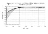
具体的に、第1,第2光学軸方位角が16.3°,59.6°に設定された第1,第2
水晶板633,634の板厚d1,d2を図7の関係に基づいて設定し、かつ、光線進行
角度θ5を0°に設定した場合、1/2波長板632の三色偏光変換効率は、図9に示す
ようになった。
この図9から、第1水晶板633の板厚d1が21.2μm〜50.0μmの場合、三
色変換効率が0.8以上となることがわかる。そして、図7から、三色変換効率を0.8
以上にするための第2水晶板634の板厚d2は、13.5μm〜31.9μmであるこ
とがわかる。
そして、第1,第2水晶板633,634の板厚d1,d2が下限値(21.2μm,
13.5μm)、上限値(50.0μm,31.9μm)の場合、三色偏光変換効率は、
以下のようになった。
Specifically, the first and second azimuth angles of the first and second optical axes are set to 16.3 ° and 59.6 °, respectively.
When the plate thicknesses d1 and d2 of the
From FIG. 9, it can be seen that when the plate thickness d1 of the
It can be seen that the plate thickness d2 of the
The plate thicknesses d1 and d2 of the first and
13.5 μm) and upper limit values (50.0 μm, 31.9 μm), the trichromatic polarization conversion efficiency is
It became as follows.
板厚d1,d2が下限値、光線進行角度θ5が0°、入射角度θ6が−10°〜+10
°のときの偏光変換効率は、図10に示すようになった。
ここで、図10のグラフにおいて、各入射角度θ6での偏光変換効率に大きな差異がな
いため、数本の線しか描かれていないように示されているが、実際には11本の線が描か
れている。
さらに、板厚d1,d2が下限値、光線進行角度θ5が90°、入射角度θ6が−10
°〜+10°のときの偏光変換効率は、図11に示すようになった。また、板厚d1,d
2が上限値、光線進行角度θ5が0°,+90°、入射角度θ6が−10°〜+10°の
ときの偏光変換効率は、図12、図13に示すようになった。
そして、図10〜図13の関係に基づいて、板厚d1,d2が下限値、上限値の1/2
波長板632における三色偏光変換効率、つまり図10〜図13に示すような三色波長帯
領域Aaで囲まれる部分において平均したものを求めた。また、板厚d1,d2が下限値
よりも小さい12.5μm,7.9μmの場合、上限値よりも大きい69.6μm,44
.4μmの場合の三色偏光変換効率を求めた。さらに、三色偏光変換効率が最大となる板
厚d1,d2を求めた。それらの結果を表1に示す。
The plate thicknesses d1 and d2 are lower limit values, the light beam traveling angle θ5 is 0 °, and the incident angle θ6 is −10 ° to +10.
The polarization conversion efficiency at ° was as shown in FIG.
Here, in the graph of FIG. 10, since there is no great difference in the polarization conversion efficiency at each incident angle θ6, only a few lines are drawn, but in reality, 11 lines are shown. It is drawn.
Further, the plate thicknesses d1 and d2 are lower limit values, the light beam traveling angle θ5 is 90 °, and the incident angle θ6 is −10.
FIG. 11 shows the polarization conversion efficiency when the angle is from .degree. To + 10.degree. Moreover, plate thickness d1, d
The polarization conversion efficiencies when 2 is the upper limit value, the light beam traveling angle θ5 is 0 °, + 90 °, and the incident angle θ6 is −10 ° to + 10 ° are as shown in FIGS.
And based on the relationship of FIGS. 10-13, plate | board thickness d1, d2 is a lower limit and 1/2 of an upper limit.
The three-color polarization conversion efficiency in the
. The trichromatic polarization conversion efficiency in the case of 4 μm was determined. Further, plate thicknesses d1 and d2 that maximize the three-color polarization conversion efficiency were obtained. The results are shown in Table 1.
表1に示すように、板厚d1,d2が下限値、上限値の1/2波長板632における三
色偏光変換効率は、いずれも0.8以上となっていることがわかる。また、板厚d1,d
2が下限値よりも小さい、あるいは、上限値よりも大きい場合、三色偏光変換効率は、0
.8未満となっていることがわかる。つまり、偏光変換素子6が入射光対応状態で設置さ
れることで、板厚d1,d2が21.2μm〜50.0μm,13.5μm〜31.9μ
mの第1,第2水晶板633,634から構成される1/2波長板632が第1光入射面
611に対して45°傾斜した状態となる場合、1/2波長板632の三色偏光変換効率
は、0.8以上になる。
As shown in Table 1, it can be seen that the trichromatic polarization conversion efficiencies in the half-
When 2 is smaller than the lower limit value or larger than the upper limit value, the trichromatic polarization conversion efficiency is 0
. It turns out that it is less than 8. That is, when the
When the half-
次に、第1実施形態の偏光変換素子6を用いたプロジェクタの一例を図14に基づいて
説明する。
プロジェクタ1は、外装筺体2と、投射光学装置としての投射レンズ3と、光学ユニッ
ト4等を備える。
光学ユニット4は、光源装置41と、均一照明光学装置42と、色分離光学装置43と
、リレー光学装置44と、光学装置45と、これら光学部品42〜45を内部に収納配置
する光学部品用筐体46とを備える。
光源装置41は、光源ランプ411と、リフレクタ412と、平行化レンズ413とを
有しており、光源ランプ411から射出された放射状の光束をリフレクタ412にて反射
させ、平行化レンズ413を介して平行光として射出する。
Next, an example of a projector using the
The
The optical unit 4 includes a
The
均一照明光学装置42は、第1レンズアレイ421と、第2レンズアレイ422と、上
述の偏光変換素子6と、重畳レンズ424とを備える。
第1レンズアレイ421は、入射光軸方向から見て略矩形状の輪郭を有する第1小レン
ズが、入射光軸に対し略直交する面内においてマトリクス状に配列された構成を有してい
る。各第1小レンズは、光源装置41から射出される光束を複数の部分光束に分割してい
る。
第2レンズアレイ422は、第1レンズアレイ421と略同様な構成を有しており、第
2小レンズがマトリクス状に配列された構成を有している。この第2レンズアレイ422
は、重畳レンズ424とともに、第1レンズアレイ421の各第1小レンズの像を光学装
置45の後述する液晶パネル上に結像させる機能を有している。
The uniform illumination
The
The
Has a function of forming an image of each first small lens of the
偏光変換素子6は、第2レンズアレイ422と重畳レンズ424との間に、プロジェク
タ1の設計上の照明光軸と、第1,第2光入射面611,621とが直交し、かつ、第1
,第2水晶板633,634の第1,第2光学軸方位角が16.3°,59.6°となる
ように設置されている。ここで、第2レンズアレイ422の焦点位置などにより、第2レ
ンズアレイ422からの射出光が第1,第2光入射面611,621に−10°〜+10
°の入射角度で入射される。つまり、偏光変換素子6は、入射光対応状態で設置されてい
る。
この偏光変換素子6は、第2レンズアレイ422からの三色波長帯の光のS偏光成分を
偏光分離膜631および反射膜65で反射して射出するとともに、偏光分離膜631を透
過したP偏光成分を1/2波長板632により0.8以上の三色偏光変換効率でS偏光成
分に変換して射出する。つまり、偏光変換素子6は、略1種類の偏光光に変換する。
具体的に、偏光変換素子6によって略1種類の偏光光に変換された各部分光は、重畳レ
ンズ424によって最終的に光学装置45の後述する液晶パネル上にほぼ重畳される。偏
光光を変調するタイプの液晶パネルを用いたプロジェクタでは、1種類の偏光光しか利用
できないため、ランダムな偏光光を発する光源装置41からの光の略半分を利用できない
。このため、偏光変換素子6を用いることで、光源装置41からの射出光を略1種類の偏
光光に変換し、光学装置45での光の利用効率を高めている。
In the
The first and second optical axis azimuth angles of the
Incident at an incident angle of °. That is, the
The
Specifically, each partial light converted into approximately one type of polarized light by the
色分離光学装置43は、2枚のダイクロイックミラー431,432と、反射ミラー4
33とを備え、ダイクロイックミラー431,432により均一照明光学装置42から射
出された複数の部分光束を、赤、緑、青の3色の色光に分離する機能を有している。
リレー光学装置44は、入射側レンズ441、リレーレンズ443、及び反射ミラー4
42,444を備え、色分離光学装置43で分離された赤色光を光学装置45の後述する
赤色光用の液晶パネルまで導く機能を有している。
The color separation
33, and has a function of separating a plurality of partial light beams emitted from the uniform illumination
The relay
42 and 444, and has a function of guiding the red light separated by the color separation
この際、色分離光学装置43のダイクロイックミラー431では、均一照明光学装置4
2から射出された光束の青色光成分が反射するとともに、赤色光成分と緑色光成分とが透
過する。ダイクロイックミラー431によって反射した青色光は、反射ミラー433で反
射し、フィールドレンズ425を通って光学装置45の後述する青色光用の液晶パネルに
達する。
このフィールドレンズ425は、第2レンズアレイ422から射出された各部分光束を
その中心軸(主光線)に対して平行な光束に変換する。他の緑色光用、赤色光用の液晶パ
ネルの光束入射側に設けられたフィールドレンズ425も同様である。
At this time, in the
The blue light component of the light beam emitted from 2 is reflected, and the red light component and the green light component are transmitted. The blue light reflected by the
The
ダイクロイックミラー431を透過した赤色光と緑色光のうちで、緑色光はダイクロイ
ックミラー432によって反射し、フィールドレンズ425を通って光学装置45の後述
する緑色光用の液晶パネルに達する。一方、赤色光はダイクロイックミラー432を透過
してリレー光学装置44を通り、さらにフィールドレンズ425を通って光学装置45の
後述する赤色光用の液晶パネルに達する。
Of the red light and green light transmitted through the
光学装置45は、光変調装置としての3枚の液晶パネル451(赤色光用の液晶パネル
を451R、緑色光用の液晶パネルを451G、青色光用の液晶パネルを451Bとする
)と、これら液晶パネル451の光束入射側及び光束射出側にそれぞれ配置される偏光素
子5と、クロスダイクロイックプリズム454とを備える。
The
偏光素子5は、各液晶パネル451の光束入射側にそれぞれ配置される入射側偏光板5
Aと、各液晶パネル451の光束射出側にそれぞれ配置される射出側偏光板5Bとを備え
る。
入射側偏光板5Aは、色分離光学装置43で分離された各色光のうち、偏光変換素子6
で揃えられた偏光方向と略同一方向の偏光方向を有する偏光光のみ透過させ、その他の光
束を吸収するものである。
液晶パネル451は、入射側偏光板5Aから射出された偏光光束の偏光方向を変調する
。
射出側偏光板5Bは、入射側偏光板5Aと略同様の構成を有し、液晶パネル451の画
像形成領域から射出された光束のうち、入射側偏光板5Aにおける光束の透過軸と直交す
る偏光方向を有する光束のみ透過させ、その他の光束を吸収する。
The
A and an exit-side
The incident-side
Only the polarized light having a polarization direction substantially the same as the polarization direction aligned in (1) is transmitted, and other light beams are absorbed.
The
The exit-side
クロスダイクロイックプリズム454は、射出側偏光板5Bから射出された色光毎に変
調された光学像を合成してカラー画像を形成する。このクロスダイクロイックプリズム4
54で形成されたカラー画像は、上述した投射レンズ3によりスクリーン等へ拡大投射さ
れる。
The cross
The color image formed at 54 is enlarged and projected onto the screen or the like by the
従って、第1実施形態では、次の作用効果を奏することができる。
偏光変換素子6の1/2波長板632を構成する第1,第2水晶板633,634の板
厚d1,d2を21.2μm〜50.0μm,13.5μm〜31.9μmに設定してい
るので、偏光変換素子6を入射光対応状態で設置したときの1/2波長板632での三色
偏光変換効率を0.8以上にすることができる。従って、偏光変換素子6をプロジェクタ
1における第2レンズアレイ422の光射出側に設置した場合でも、つまり−10°〜+
10°の入射角度で入射光が入射される場合であっても、1/2波長板632で三色波長
帯の入射光を0.8以上の三色偏光変換効率で偏光光に変換することができ、実用性を有
する偏光変換素子6を提供できる。さらに、1/2波長板632を上記式(1)に基づく
性能を有する第1,第2水晶板633,634で構成しているので、高い偏光変換効率を
有する偏光変換素子6を提供できる。
また、偏光変換素子6をプロジェクタ1に使用すると、実用的に問題がない青色成分、
緑色成分、赤色成分の再現性を有し、かつ、問題がない明るさの映像を投射できる。
Therefore, in the first embodiment, the following operational effects can be achieved.
The plate thicknesses d1 and d2 of the first and
Even when incident light is incident at an incident angle of 10 °, incident light in the three-color wavelength band is converted into polarized light with a three-color polarization conversion efficiency of 0.8 or more by the half-
Further, when the
A reproducible green component and a red component can be projected, and an image having brightness with no problem can be projected.
次に、本発明の第2実施形態を図面に基づいて説明する。この第2実施形態では、青色
偏光変換効率が0.8以上の1/2波長板を有する偏光変換素子について説明する。
図1、図2に示すように、偏光変換素子6Aを構成する1/2波長板636は、Yカッ
ト水晶基板を基にして、板厚d11,d12が16.8μm〜43.7μm,10.7μ
m〜27.8μmの板状に形成された第1,第2水晶板637,638から構成されてい
る。この1/2波長板636は、入射面633Bに45°の入射角度で入射光LのP偏光
成分が入射される状態で、かつ、第1,第2水晶板637,638の第1,第2光学軸方
位角が16.3°,59.6°となる状態で設けられる。また、1/2波長板636は、
上記式(1)に基づく性能を有する第1,第2水晶板637,638から構成されている
。
Next, 2nd Embodiment of this invention is described based on drawing. In the second embodiment, a polarization conversion element having a half-wave plate with a blue polarization conversion efficiency of 0.8 or more will be described.
As shown in FIGS. 1 and 2, the half-wave plate 636 constituting the polarization conversion element 6A is based on a Y-cut quartz substrate and has plate thicknesses d11 and d12 of 16.8 μm to 43.7 μm, 10. 7μ
The first and second crystal plates 637 and 638 are formed in a plate shape of m to 27.8 μm. The half-wave plate 636 is in a state in which the P-polarized component of the incident light L is incident on the
It consists of first and second quartz plates 637 and 638 having performance based on the above formula (1).
そして、第1実施形態の1/2波長板632と同様の方法により、光線進行角度θ5が
0°、入射光Lの入射角度θ6が−10°〜+10°のときの青色波長帯(400nm〜
500nm)における平均偏光変換効率を求め、青色波長帯全域において平均したものを
、1/2波長板636の青色偏光変換効率として求めた。
Then, by the same method as the half-
The average polarization conversion efficiency at 500 nm) was obtained and averaged over the entire blue wavelength band was obtained as the blue polarization conversion efficiency of the half-wave plate 636.
具体的に、第1,第2光学軸方位角が16.3°,59.6°に設定された第1,第2
水晶板637,638の板厚d11,d12を図7の関係に基づいて設定し、かつ、光線
進行角度θ5を0°に設定した場合の1/2波長板636の青色偏光変換効率は、図9に
示すようになった。
この図9および図7から、第1,第2水晶板637,638の板厚d11,d12が1
6.8μm〜43.7μm,10.7μm〜27.8μmの場合、青色変換効率が0.8
以上となることがわかる。
そして、第1,第2水晶板637,638の板厚d11,d12が下限値(16.8μ
m,10.7μm)、上限値(43.7μm,27.8μm)の場合、青色偏光変換効率
は、以下のようになった。
Specifically, the first and second azimuth angles of the first and second optical axes are set to 16.3 ° and 59.6 °, respectively.
The blue polarization conversion efficiency of the half-wave plate 636 when the plate thicknesses d11 and d12 of the quartz plates 637 and 638 are set based on the relationship of FIG. 7 and the light beam traveling angle θ5 is set to 0 ° is shown in FIG. It came to show in 9.
From FIG. 9 and FIG. 7, the plate thicknesses d11 and d12 of the first and second crystal plates 637 and 638 are 1.
In the case of 6.8 μm to 43.7 μm and 10.7 μm to 27.8 μm, the blue conversion efficiency is 0.8.
It turns out that it becomes the above.
The plate thicknesses d11 and d12 of the first and second crystal plates 637 and 638 are lower limit values (16.8 μm).
m, 10.7 μm) and upper limit values (43.7 μm, 27.8 μm), the blue polarization conversion efficiency was as follows.
板厚d11,d12が下限値の場合、光線進行角度θ5が−0°、+90°のときの偏
光変換効率は、図15、図16に示すようになった。さらに、板厚d11,d12が上限
値の場合、光線進行角度θ5が0°、+90°のときの偏光変換効率は、図17、図18
に示すようになった。
そして、図15〜図18に示すような青色波長帯領域Abで囲まれる部分の偏光変換効
率を平均したものを、板厚d11,d12が下限値、上限値の1/2波長板636におけ
る青色偏光変換効率として求めた。また、板厚d11,d12が12.5μm,7.9μ
mの場合、69.6μm,44.4μmの場合のそれぞれにおける青色偏光変換効率を求
めた。さらに、青色偏光変換効率が最大となる板厚d11,d12を求めた。それらの結
果を表2に示す。
When the plate thicknesses d11 and d12 are the lower limit values, the polarization conversion efficiencies when the light beam traveling angle θ5 is −0 ° and + 90 ° are as shown in FIGS. Further, when the plate thicknesses d11 and d12 are the upper limit values, the polarization conversion efficiencies when the light beam traveling angle θ5 is 0 ° and + 90 ° are shown in FIGS.
It came to show in.
Then, the average of the polarization conversion efficiencies of the portions surrounded by the blue wavelength band region Ab as shown in FIGS. 15 to 18 is the blue color in the half-wave plate 636 in which the plate thicknesses d11 and d12 are the lower limit value and the upper limit value. The polarization conversion efficiency was obtained. Further, the plate thicknesses d11 and d12 are 12.5 μm and 7.9 μm.
In the case of m, the blue polarization conversion efficiency in each of the cases of 69.6 μm and 44.4 μm was obtained. Further, plate thicknesses d11 and d12 that maximize the blue polarization conversion efficiency were obtained. The results are shown in Table 2.
表2に示すように、板厚d11,d12が下限値、上限値の1/2波長板636におけ
る青色偏光変換効率は、いずれも0.8以上となっていることがわかる。また、板厚d1
1,d12が下限値よりも小さい場合、上限値よりも大きい場合、青色偏光変換効率は、
0.8未満となっていることがわかる。つまり、偏光変換素子6Aが入射光対応状態で設
置されることで、板厚d11,d12が16.8μm〜43.7μm,10.7μm〜2
7.8μmの第1,第2水晶板637,638から構成される1/2波長板636が第1
光入射面611に対して45°傾斜した状態となる場合、1/2波長板636の青色偏光
変換効率は、0.8以上になる。
As shown in Table 2, it can be seen that the blue polarization conversion efficiencies of the half-wave plates 636 with the plate thicknesses d11 and d12 being the lower limit value and the upper limit value are both 0.8 or more. Also, the plate thickness d1
1, d12 is smaller than the lower limit value, if larger than the upper limit value, the blue polarization conversion efficiency is
It turns out that it is less than 0.8. That is, by installing the polarization conversion element 6A in a state corresponding to incident light, the plate thicknesses d11 and d12 are 16.8 μm to 43.7 μm and 10.7 μm to 2 respectively.
A half-wave plate 636 composed of 7.8 μm first and second crystal plates 637 and 638 is the first.
In a state where the
この第2実施形態の偏光変換素子6Aは、例えば図14に示すようなプロジェクタ1の
光源装置41の代わりに、青色波長帯のみの光を射出する青色光源装置、緑色波長帯のみ
の光を射出する緑色光源装置、赤色波長帯のみの光を射出する赤色光源装置を備えたプロ
ジェクタ(以下、RGB光源プロジェクタと称す)に適用することができる。具体的には
、偏光変換素子6Aは、RGB光源プロジェクタの青色光源装置の設計上の照明光軸と、
第1,第2光入射面611,621とが直交し、かつ、第1,第2水晶板637,638
の第1,第2光学軸方位角が16.3°,59.6°となるように、つまり入射光対応状
態で設置される。
また、偏光変換素子6Aは、図14に示すような構成のうち偏光変換素子6が設けられ
ていないプロジェクタ1において、ダイクロイックミラー431と、入射側偏光板5Aと
の間の光路中に、上述の入射光対応状態で設置される。
この偏光変換素子6Aは、入射される青色波長帯の入射光を0.8以上の青色偏光変換
効率でS偏光成分に変換して射出する。
The polarization conversion element 6A according to the second embodiment emits light of only a blue wavelength band, and emits light of only a green wavelength band, for example, instead of the
The first and second light incident surfaces 611 and 621 are orthogonal to each other, and the first and second crystal plates 637 and 638 are used.
The first and second optical axis azimuth angles are set to 16.3 ° and 59.6 °, that is, in a state corresponding to incident light.
Further, in the
This polarization conversion element 6A converts incident light in the blue wavelength band into an S-polarized component with a blue polarization conversion efficiency of 0.8 or more and emits it.
従って、第2実施形態では、次の作用効果を奏することができる。
偏光変換素子6Aの1/2波長板636を構成する第1,第2水晶板637,638の
板厚d11,d12を16.8μm〜43.7μm,10.7μm〜27.8μmに設定
しているので、偏光変換素子6Aを入射光対応状態で設置したときの1/2波長板636
での青色偏光変換効率を0.8以上にすることができ、実用性を有する偏光変換素子6A
を提供できる。さらに、1/2波長板636を上記式(1)に基づく性能を有する第1,
第2水晶板637,638で構成しているので、高い偏光変換効率を有する偏光変換素子
6Aを提供できる。
また、偏光変換素子6AをRGB光源プロジェクタに使用すると、実用的に問題がない
青色成分の再現性を有し、かつ、問題がない明るさの映像を投射できる。
Therefore, in the second embodiment, the following operational effects can be achieved.
The plate thicknesses d11 and d12 of the first and second crystal plates 637 and 638 constituting the half-wave plate 636 of the polarization conversion element 6A are set to 16.8 μm to 43.7 μm and 10.7 μm to 27.8 μm, respectively. Therefore, the half-wave plate 636 when the polarization conversion element 6A is installed in a state corresponding to incident light.
The polarization conversion element 6A having blue light conversion efficiency at 0.8 can be made 0.8 or more and has practicality
Can provide. Further, the half-wave plate 636 has the first performance having the performance based on the above formula (1).
Since the second crystal plates 637 and 638 are used, the polarization conversion element 6A having high polarization conversion efficiency can be provided.
Further, when the polarization conversion element 6A is used for an RGB light source projector, it is possible to project an image having a reproducibility of a blue component that has no practical problem and brightness with no problem.
次に、本発明の第3実施形態を図面に基づいて説明する。この第3実施形態では、緑色
偏光変換効率が0.8以上の1/2波長板を有する偏光変換素子について説明する。
図1、図2に示すように、偏光変換素子6Bを構成する1/2波長板640は、Yカッ
ト水晶基板を基にして、板厚d21,d22が21.0μm〜55.6μm,13.4μ
m〜35.4μmの板状に形成された第1,第2水晶板641,642から構成されてい
る。この1/2波長板640は、入射面633Bに45°の入射角度で入射光LのP偏光
成分が入射される状態で、かつ、第1,第2水晶板641,642の第1,第2光学軸方
位角が16.3°,59.6°となる状態で設けられる。また、1/2波長板640は、
上記式(1)に基づく性能を有する第1,第2水晶板641,642から構成されている
。
Next, 3rd Embodiment of this invention is described based on drawing. In the third embodiment, a polarization conversion element having a half-wave plate with a green polarization conversion efficiency of 0.8 or more will be described.
As shown in FIGS. 1 and 2, the half-wave plate 640 constituting the polarization conversion element 6B is based on a Y-cut quartz substrate and has thicknesses d21 and d22 of 21.0 μm to 55.6 μm, 13. 4μ
The first and second crystal plates 641 and 642 are formed in a plate shape of m to 35.4 μm. The half-wave plate 640 is in a state in which the P-polarized component of the incident light L is incident on the
It consists of first and second crystal plates 641 and 642 having performance based on the above formula (1).
そして、第1実施形態の1/2波長板632と同様の方法により、光線進行角度θ5が
0°、入射光Lの入射角度θ6が−10°〜+10°のときの緑色波長帯(500nm〜
600nm)における平均偏光変換効率を求め、緑色波長帯全域において平均したものを
、1/2波長板640の緑色偏光変換効率として求めた。
Then, by the same method as that of the half-
The average polarization conversion efficiency at 600 nm) was obtained and averaged over the entire green wavelength band was obtained as the green polarization conversion efficiency of the half-wave plate 640.
具体的に、第1,第2光学軸方位角が16.3°,59.6°に設定された第1,第2
水晶板641,642の板厚d21,d22を図7の関係に基づいて設定し、かつ、光線
進行角度θ5を0°に設定した場合の1/2波長板640の緑色偏光変換効率は、図9に
示すようになった。
この図9および図7から、第1,第2水晶板641,642の板厚d21,d22が2
1.0μm〜55.6μm,13.4μm〜35.4μmの場合、緑色変換効率が0.8
以上となることがわかる。
そして、第1,第2水晶板641,642の板厚d21,d22が下限値(16.8μ
m,10.7μm)、上限値(43.7μm,27.8μm)の場合、緑色偏光変換効率
は、以下のようになった。
Specifically, the first and second azimuth angles of the first and second optical axes are set to 16.3 ° and 59.6 °, respectively.
The green polarization conversion efficiency of the half-wave plate 640 when the plate thicknesses d21 and d22 of the quartz plates 641 and 642 are set based on the relationship of FIG. 7 and the light beam traveling angle θ5 is set to 0 ° is shown in FIG. It came to show in 9.
9 and 7, the thicknesses d21 and d22 of the first and second crystal plates 641 and 642 are 2 respectively.
In the case of 1.0 μm to 55.6 μm and 13.4 μm to 35.4 μm, the green conversion efficiency is 0.8.
It turns out that it becomes the above.
The plate thicknesses d21 and d22 of the first and second crystal plates 641 and 642 are lower limit values (16.8 μm).
m, 10.7 μm) and upper limit values (43.7 μm, 27.8 μm), the green polarization conversion efficiency was as follows.
板厚d21,d22が下限値の場合、光線進行角度θ5が−0°、+90°のときの偏
光変換効率は、図19、図20に示すようになった。さらに、板厚d21,d22が上限
値の場合、光線進行角度θ5が0°、+90°のときの偏光変換効率は、図21、図22
に示すようになった。
そして、図19〜図22に示すような緑色波長帯領域Agで囲まれる部分の偏光変換効
率を平均したものを、板厚d21,d22が下限値、上限値の1/2波長板640におけ
る緑色偏光変換効率として求めた。また、板厚d21,d22が12.5μm,7.9μ
mの場合、69.6μm,44.4μmの場合のそれぞれにおける緑色偏光変換効率を求
めた。さらに、緑色偏光変換効率が最大となる板厚d21,d22を求めた。それらの結
果を表3に示す。
When the plate thicknesses d21 and d22 are the lower limit values, the polarization conversion efficiencies when the light beam traveling angle θ5 is −0 ° and + 90 ° are as shown in FIGS. Furthermore, when the plate thicknesses d21 and d22 are the upper limit values, the polarization conversion efficiencies when the light beam traveling angle θ5 is 0 ° and + 90 ° are shown in FIGS.
It came to show in.
Then, the average of the polarization conversion efficiencies of the portions surrounded by the green wavelength band region Ag as shown in FIGS. 19 to 22 is the green color in the half-wave plate 640 with the plate thicknesses d21 and d22 being the lower limit value and the upper limit value. The polarization conversion efficiency was obtained. The plate thicknesses d21 and d22 are 12.5 μm and 7.9 μm.
In the case of m, green polarization conversion efficiencies in the cases of 69.6 μm and 44.4 μm were obtained. Further, plate thicknesses d21 and d22 that maximize the green polarization conversion efficiency were obtained. The results are shown in Table 3.
表3に示すように、板厚d21,d22が下限値、上限値の1/2波長板640におけ
る緑色偏光変換効率は、いずれも0.8以上となっていることがわかる。また、板厚d2
1,d22が下限値よりも小さい場合、上限値よりも大きい場合、緑色偏光変換効率は、
0.8未満となっていることがわかる。つまり、偏光変換素子6Bが入射光対応状態で設
置されることで、板厚d21,d22が21.0μm〜55.6μm,13.4μm〜3
5.4μmの第1,第2水晶板641,642から構成される1/2波長板640が第1
光入射面611に対して45°傾斜した状態となる場合、1/2波長板640の緑色偏光
変換効率は、0.8以上になる。
As shown in Table 3, it can be seen that the green polarization conversion efficiencies of the half-wave plates 640 with the plate thicknesses d21 and d22 being the lower limit value and the upper limit value are both 0.8 or more. Also, the plate thickness d2
1, d22 is smaller than the lower limit value, if larger than the upper limit value, the green polarization conversion efficiency is
It turns out that it is less than 0.8. That is, when the polarization conversion element 6B is installed in a state corresponding to incident light, the plate thicknesses d21 and d22 are 21.0 μm to 55.6 μm, 13.4 μm to 3
A half-wave plate 640 composed of 5.4 μm first and second crystal plates 641 and 642 is the first.
When the state is inclined by 45 ° with respect to the
この第3実施形態の偏光変換素子6Bは、例えばRGB光源プロジェクタの緑色光源装
置の設計上の照明光軸上に、上述の入射光対応状態で設置される。
また、偏光変換素子6Bは、図14に示すような構成のうち偏光変換素子6が設けられ
ていないプロジェクタ1において、ダイクロイックミラー432と、入射側偏光板5Aと
の間の光路中に、上述の入射光対応状態で設置される。
この偏光変換素子6Bは、入射される緑色波長帯の入射光を0.8以上の緑色偏光変換
効率でS偏光成分に変換して射出する。
For example, the polarization conversion element 6B of the third embodiment is installed on the illumination optical axis in the design of the green light source device of the RGB light source projector in a state corresponding to the incident light described above.
Further, in the
This polarization conversion element 6B converts the incident light in the green wavelength band into an S-polarized component with a green polarization conversion efficiency of 0.8 or more and emits it.
従って、第3実施形態では、次の作用効果を奏することができる。
偏光変換素子6Bの1/2波長板640を構成する第1,第2水晶板641,642の
板厚d21,d22を21.0μm〜55.6μm,13.4μm〜35.4μmに設定
しているので、偏光変換素子6Bを入射光対応状態で設置したときの1/2波長板640
での緑色偏光変換効率を0.8以上にすることができ、実用性を有する偏光変換素子6B
を提供できる。さらに、1/2波長板640を上記式(1)に基づく性能を有する第1,
第2水晶板641,642で構成しているので、高い偏光変換効率を有する偏光変換素子
6Bを提供できる。
また、偏光変換素子6Bをプロジェクタ1に使用すると、実用的に問題がない緑色成分
の再現性を有し、かつ、問題がない明るさの映像を投射できる。
Therefore, in the third embodiment, the following operational effects can be achieved.
The plate thicknesses d21 and d22 of the first and second crystal plates 641 and 642 constituting the half-wave plate 640 of the polarization conversion element 6B are set to 21.0 μm to 55.6 μm and 13.4 μm to 35.4 μm, respectively. Therefore, the half-wave plate 640 when the polarization conversion element 6B is installed in a state corresponding to incident light.
The polarization conversion element 6B has a practicality that can make the green polarization conversion efficiency at 0.8 or more.
Can provide. Furthermore, the half-wave plate 640 has the first performance having the performance based on the above formula (1).
Since the second crystal plates 641 and 642 are used, the polarization conversion element 6B having high polarization conversion efficiency can be provided.
Further, when the polarization conversion element 6B is used in the
次に、本発明の第4実施形態を図面に基づいて説明する。この第4実施形態では、赤色
偏光変換効率が0.8以上の1/2波長板を有する偏光変換素子について説明する。
図1、図2に示すように、偏光変換素子6Cを構成する1/2波長板644は、Yカッ
ト水晶基板を基にして、板厚d31,d32が25.3μm〜67.2μm,16.1μ
m〜42.8μmの板状に形成された第1,第2水晶板645,646から構成されてい
る。この1/2波長板644は、入射面633Bに45°の入射角度で入射光LのP偏光
成分が入射される状態で、かつ、第1,第2水晶板645,646の第1,第2光学軸方
位角が16.3°,59.6°となる状態で設けられる。また、1/2波長板644は、
上記式(1)に基づく性能を有する第1,第2水晶板645,646から構成されている
。
Next, 4th Embodiment of this invention is described based on drawing. In the fourth embodiment, a polarization conversion element having a half-wave plate with a red polarization conversion efficiency of 0.8 or more will be described.
As shown in FIGS. 1 and 2, the half-wave plate 644 constituting the polarization conversion element 6C is based on a Y-cut quartz substrate and has plate thicknesses d31 and d32 of 25.3 μm to 67.2 μm, 16. 1μ
The first and second crystal plates 645 and 646 are formed in a plate shape of m to 42.8 μm. The half-wave plate 644 is in a state in which the P-polarized component of the incident light L is incident on the
The first and second quartz plates 645 and 646 having performance based on the above formula (1) are included.
そして、第1実施形態の1/2波長板632と同様の方法により、光線進行角度θ5が
0°、入射光Lの入射角度θ6が−10°〜+10°のときの赤色波長帯(600nm〜
700nm)における平均偏光変換効率を求め、赤色波長帯全域において平均したものを
、1/2波長板644の赤色偏光変換効率として求めた。
Then, by the same method as the half-
The average polarization conversion efficiency at 700 nm) was obtained, and the average polarization conversion efficiency over the entire red wavelength band was obtained as the red polarization conversion efficiency of the half-wave plate 644.
具体的に、第1,第2光学軸方位角が16.3°,59.6°に設定された第1,第2
水晶板645,646の板厚d31,d32を図7の関係に基づいて設定し、かつ、光線
進行角度θ5を0°に設定した場合の1/2波長板644の赤色偏光変換効率は、図9に
示すようになった。
この図9および図7から、第1,第2水晶板645,646の板厚d31,d32が2
5.3μm〜67.2μm,16.1μm〜42.8μmの場合、赤色変換効率が0.8
以上となることがわかる。
そして、第1,第2水晶板645,646の板厚d31,d32が下限値(25.3μ
m,16.1μm)、上限値(67.2μm,42.8μm)の場合、赤色偏光変換効率
は、以下のようになった。
Specifically, the first and second azimuth angles of the first and second optical axes are set to 16.3 ° and 59.6 °, respectively.
The red polarization conversion efficiency of the half-wave plate 644 when the plate thicknesses d31 and d32 of the quartz plates 645 and 646 are set based on the relationship of FIG. 7 and the light beam traveling angle θ5 is set to 0 ° is shown in FIG. It came to show in 9.
9 and 7, the thicknesses d31 and d32 of the first and second crystal plates 645 and 646 are 2 respectively.
In the case of 5.3 μm to 67.2 μm and 16.1 μm to 42.8 μm, the red conversion efficiency is 0.8.
It turns out that it becomes the above.
The plate thicknesses d31 and d32 of the first and second crystal plates 645 and 646 are lower limit values (25.3 μm).
m, 16.1 μm) and upper limit values (67.2 μm, 42.8 μm), the red polarization conversion efficiency was as follows.
板厚d31,d32が下限値の場合、光線進行角度θ5が−0°、+90°のときの偏
光変換効率は、図23、図24に示すようになった。さらに、板厚d31,d32が上限
値の場合、光線進行角度θ5が0°、+90°のときの偏光変換効率は、図25、図26
に示すようになった。
そして、図23〜図26に示すような赤色波長帯領域Arで囲まれる部分の偏光変換効
率を平均したものを、板厚d31,d32が下限値、上限値の1/2波長板644におけ
る赤色偏光変換効率として求めた。また、板厚d31,d32が25.3μm〜67.2
μmの場合、16.1μm〜42.8μmの場合のそれぞれにおける赤色偏光変換効率を
求めた。さらに、赤色偏光変換効率が最大となる板厚d31,d32を求めた。それらの
結果を表4に示す。
When the plate thicknesses d31 and d32 are the lower limit values, the polarization conversion efficiencies when the light beam traveling angle θ5 is −0 ° and + 90 ° are as shown in FIGS. Further, when the plate thicknesses d31 and d32 are the upper limit values, the polarization conversion efficiencies when the light beam traveling angle θ5 is 0 ° and + 90 ° are shown in FIGS.
It came to show in.
The average of the polarization conversion efficiencies of the portions surrounded by the red wavelength band region Ar as shown in FIGS. 23 to 26 is the red color in the half-wave plate 644 whose plate thicknesses d31 and d32 are the lower limit value and the upper limit value. The polarization conversion efficiency was obtained. Further, the plate thicknesses d31 and d32 are 25.3 μm to 67.2.
In the case of μm, the red polarization conversion efficiency in each of the case of 16.1 μm to 42.8 μm was obtained. Further, plate thicknesses d31 and d32 that maximize the red polarization conversion efficiency were obtained. The results are shown in Table 4.
表4に示すように、板厚d31,d32が下限値、上限値の1/2波長板644におけ
る赤色偏光変換効率は、いずれも0.8以上となっていることがわかる。また、板厚d3
1,d32が下限値よりも小さい場合、上限値よりも大きい場合、赤色偏光変換効率は、
0.8未満となっていることがわかる。つまり、偏光変換素子6Cが入射光対応状態で設
置されることで、板厚d31,d32が25.3μm〜67.2μm,16.1μm〜4
2.8μmの第1,第2水晶板645,646から構成される1/2波長板644が第1
光入射面611に対して45°傾斜した状態となる場合、1/2波長板644の赤色偏光
変換効率は、0.8以上になる。
As shown in Table 4, it can be seen that the red polarization conversion efficiencies of the half-wave plates 644 whose plate thicknesses d31 and d32 are the lower limit value and the upper limit value are both 0.8 or more. Also, the plate thickness d3
1, when d32 is smaller than the lower limit value and larger than the upper limit value, the red polarization conversion efficiency is
It turns out that it is less than 0.8. That is, when the polarization conversion element 6C is installed in a state corresponding to incident light, the plate thicknesses d31 and d32 are 25.3 μm to 67.2 μm and 16.1 μm to 4 respectively.
A half-wave plate 644 made up of 2.8 μm first and second crystal plates 645 and 646 is the first.
When the state is inclined by 45 ° with respect to the
この第4実施形態の偏光変換素子6Cは、例えばRGB光源プロジェクタの赤色光源装
置の設計上の照明光軸上に、上述の入射光対応状態で設置される。
また、偏光変換素子6Cは、図14に示すような構成のうち偏光変換素子6が設けられ
ていないプロジェクタ1において、反射ミラー442と、入射側偏光板5Aとの間の光路
中に、上述の入射光対応状態で設置される。
この偏光変換素子6Cは、入射される赤色波長帯の入射光を0.8以上の赤色偏光変換
効率でS偏光成分に変換して射出する。
The polarization conversion element 6C of the fourth embodiment is installed on the illumination optical axis in the design of the red light source device of the RGB light source projector, for example, in a state corresponding to the incident light described above.
Further, in the
The polarization conversion element 6C converts incident light in the red wavelength band into an S-polarized component with a red polarization conversion efficiency of 0.8 or more and emits it.
従って、第4実施形態では、次の作用効果を奏することができる。
偏光変換素子6Cの1/2波長板644を構成する第1,第2水晶板645,646の
板厚d31,d32を25.3μm〜67.2μm,16.1μm〜42.8μmに設定
しているので、偏光変換素子6Cを入射光対応状態で設置したときの1/2波長板644
での赤色偏光変換効率を0.8以上にすることができ、実用性を有する偏光変換素子6C
を提供できる。さらに、1/2波長板644を上記式(1)に基づく性能を有する第1,
第2水晶板645,646で構成しているので、高い偏光変換効率を有する偏光変換素子
6Cを提供できる。
また、偏光変換素子6Cをプロジェクタ1に使用すると、実用的に問題がない赤色成分
の再現性を有し、かつ、問題がない明るさの映像を投射できる。
Therefore, in the fourth embodiment, the following operational effects can be achieved.
The plate thicknesses d31 and d32 of the first and second crystal plates 645 and 646 constituting the half-wave plate 644 of the polarization conversion element 6C are set to 25.3 μm to 67.2 μm and 16.1 μm to 42.8 μm, respectively. Therefore, the half-wave plate 644 when the polarization conversion element 6C is installed in a state corresponding to incident light.
The polarization conversion efficiency of the polarization conversion element 6C can be made 0.8 or more and has practicality
Can provide. Further, the half-wave plate 644 has the first performance having the performance based on the above formula (1).
Since it comprises the second crystal plates 645 and 646, the polarization conversion element 6C having high polarization conversion efficiency can be provided.
Further, when the polarization conversion element 6C is used in the
プロジェクタ光源は例えば白色光の場合、波長帯による輝度分布を有する。しかし、プ
ロジェクタを観察する人間の視感度によって、上記輝度に反して一部の波長帯を明るくし
たい場合がある。また、R光(赤色光)、G光(緑色光)、B光(青色光)の単色波長帯
光源から合成された投射光を用いるプロジェクタも提案されている。
これらのプロジェクタに本願の偏光変換素子を用いれば、波長帯による偏光効率を最適
にでき、特定な波長帯の偏光光を強く得ることができるので、観察する人間は希望した色
合いが明るい映像を観察できる。
For example, in the case of white light, the projector light source has a luminance distribution according to the wavelength band. However, there are cases where it is desired to brighten some wavelength bands against the above luminance, depending on the visibility of the human observing the projector. A projector using projection light synthesized from monochromatic wavelength band light sources of R light (red light), G light (green light), and B light (blue light) has also been proposed.
If the polarization conversion element of this application is used for these projectors, the polarization efficiency in the wavelength band can be optimized, and polarized light in a specific wavelength band can be obtained strongly, so that the person observing observes an image with a desired hue. it can.
なお、本発明は前述の実施形態に限定されるものではなく、本発明の目的を達成できる
範囲での変形、改良等は本発明に含まれるものである。
例えば、偏光変換素子6、6A,6B,6Cの用途として、プロジェクタに用いる構成
を例示したが、これに限定されるものではなく、プロジェクタ以外の装置に用いてもよい
。
It should be noted that the present invention is not limited to the above-described embodiments, and modifications, improvements, and the like within the scope that can achieve the object of the present invention are included in the present invention.
For example, as the application of the
本発明は、プロジェクタ、その他の装置に用いられる偏光変換素子に利用できる。 The present invention can be used for polarization conversion elements used in projectors and other devices.
1…プロジェクタ、3…投射光学装置としての投射レンズ、6,6A,6B,6C…偏
光変換素子、41…光源装置、61,62…第1,第2透光基材、63…偏光分離変換層
、65…反射膜、451…光変調装置としての液晶パネル、611,621…第1,第2
光入射面、631…偏光分離膜、632,636,640,644…1/2波長板、63
3,637,641,645…第1水晶板、634,638,642,646…第2水晶
板、L…入射光
DESCRIPTION OF
Light incident surface, 631... Polarization separation film, 632, 636, 640, 644.
3, 637, 641, 645 ... first crystal plate, 634, 638, 642, 646 ... second crystal plate, L ... incident light
Claims (10)
前記第1位相差板に入射する直線偏光の振動面を前記入射面に投影した投影振動面と前記第1位相差板の第1結晶光学軸とのなす角度を第1光学軸方位角θaaとし、
前記投影振動面と前記第2位相差板の第2結晶光学軸とのなす角度を第2光学軸方位角θbbとし、
前記入射する直線偏光の光軸に垂直な面に前記第1結晶光学軸を投影した第1投影結晶光学軸と前記入射する直線偏光の振動面とのなす角度を第1投影光学軸方位角θaとし、
前記垂直な面に前記第2結晶光学軸を投影した第2投影結晶光学軸と前記入射する直線偏光の振動面とのなす角度を第2投影光学軸方位角θbとしたとき、
前記第1光学軸方位角θaaと前記第1投影光学軸方位角θaとの関係は、
θaa=Atan(tan(θa)/21/2)
を満足し、
前記第2光学軸方位角θbbと前記第2投影光学軸方位角θbとの関係は、
θbb=Atan(tan(θb)/21/2)
を満足し、
前記入射する直線偏光の光軸を前記入射面に投射したときの投射像と前記投影振動面とのなす角度を光線進行角度θ5とし、
前記入射面の法線に対して45°の方向と、前記入射する直線偏光の光軸とのなす角度を入射角度θ6としたき、
前記光線進行角度θ5と前記入射角度θ6は、
θ5=0°、
−10°≦θ6≦+10°
を満足し、
前記第1投影光学軸方位角θaと前記第2投影光学軸方位角θbとの関係が、設定値をαとすると、
θb=θa+α
40°<α<50°
の条件を満足し、
前記位相差Γ’aと前記位相差Γ’bは、前記第1水晶板の位相差Γaの設計目標値からのずれ量をΔΓaとし、前記第2水晶板の位相差Γbの設計目標値からのずれ量をΔΓbとすると、
Γ’a=Γa+ΔΓa、
Γ’b=Γb+ΔΓb、
Γa=180°、
Γb=180°
を満足し、
前記ΔΓaと前記ΔΓbとの関係が、式(1)を満足することを特徴とする積層位相差板。
An angle formed by a projection vibration surface obtained by projecting the vibration surface of linearly polarized light incident on the first retardation plate onto the incident surface and the first crystal optical axis of the first retardation plate is defined as a first optical axis azimuth angle θaa. ,
An angle formed by the projection vibration surface and the second crystal optical axis of the second retardation plate is a second optical axis azimuth angle θbb,
The angle formed between the first projected crystal optical axis obtained by projecting the first crystal optical axis on a plane perpendicular to the optical axis of the incident linearly polarized light and the vibrating surface of the incident linearly polarized light is the first projected optical axis azimuth angle θa. age,
When the angle formed between the second projected crystal optical axis obtained by projecting the second crystal optical axis on the vertical plane and the incident plane of the linearly polarized light is the second projected optical axis azimuth θb,
The relationship between the first optical axis azimuth angle θaa and the first projection optical axis azimuth angle θa is:
θaa = Atan (tan (θa) / 2 1/2 )
Satisfied,
The relationship between the second optical axis azimuth angle θbb and the second projection optical axis azimuth angle θb is
θbb = Atan (tan (θb) / 2 1/2 )
Satisfied,
The angle formed between the projection image when the optical axis of the incident linearly polarized light is projected onto the incident surface and the projection vibration surface is a light beam traveling angle θ5,
The angle formed between the direction of 45 ° with respect to the normal of the incident surface and the optical axis of the incident linearly polarized light is defined as an incident angle θ6.
The ray traveling angle θ5 and the incident angle θ6 are:
θ5 = 0 °,
−10 ° ≦ θ6 ≦ + 10 °
Satisfied,
When the relationship between the first projection optical axis azimuth angle θa and the second projection optical axis azimuth angle θb is set to α,
θb = θa + α
40 ° <α <50 °
Satisfy the conditions of
The phase difference Γ′a and the phase difference Γ′b are set as ΔΓa as a deviation amount from the design target value of the phase difference Γa of the first crystal plate, and from the design target value of the phase difference Γb of the second crystal plate. If the amount of deviation is ΔΓb,
Γ′a = Γa + ΔΓa,
Γ′b = Γb + ΔΓb,
Γa = 180 °,
Γb = 180 °
Satisfied,
A laminated phase difference plate, wherein the relationship between ΔΓa and ΔΓb satisfies the formula (1).
前記第1、第2位相差板の材料を水晶とし、
前記第1、第2結晶光学軸は前記入射面と平行であることを特徴とする積層位相差板。 In the laminated phase difference plate according to claim 1,
The material of the first and second retardation plates is quartz,
The laminated phase difference plate, wherein the first and second crystal optical axes are parallel to the incident surface .
λ1=400nm、λ2=700nmとしたときに、
前記第1位相差板の厚みd1が21.2μm〜50.0μmの範囲であり、
前記第2位相差板の厚みd2が13.5μm〜31.9μmの範囲であることを特徴とする積層位相差板。 In the laminated phase difference plate according to claim 2,
When λ1 = 400 nm and λ2 = 700 nm,
A thickness d1 of the first retardation plate is in a range of 21.2 μm to 50.0 μm;
A laminated retardation plate, wherein the thickness d2 of the second retardation plate is in the range of 13.5 μm to 31.9 μm .
λ1=400nm、λ2=500nmとしたときに、
前記第1位相差板の厚みd1が16.8μm〜43.7μmの範囲であり、
前記第2位相差板の厚みd2が10.7μm〜27.8μmの範囲であることを特徴とする積層位相差板。 In the laminated phase difference plate according to claim 2,
When λ1 = 400 nm and λ2 = 500 nm,
The thickness d1 of the first retardation plate is in the range of 16.8 μm to 43.7 μm,
A laminated retardation plate, wherein the thickness d2 of the second retardation plate is in the range of 10.7 μm to 27.8 μm .
λ1=500nm、λ2=600nmとしたときに、
前記第1位相差板の厚みd1が21.0μm〜55.6μmの範囲であり、
前記第2位相差板の厚みd2が13.4μm〜35.4μmの範囲であることを特徴とする積層位相差板。 In the laminated phase difference plate according to claim 2,
When λ1 = 500 nm and λ2 = 600 nm,
A thickness d1 of the first retardation plate is in a range of 21.0 μm to 55.6 μm;
The laminated retardation plate, wherein a thickness d2 of the second retardation plate is in a range of 13.4 μm to 35.4 μm .
λ1=600nm、λ2=700nmとしたときに、
前記第1位相差板の厚みd1が25.3μm〜67.2μmの範囲であり、
前記第2位相差板の厚みd2が16.1μm〜42.8μmの範囲であることを特徴とする積層位相差板。 In the laminated phase difference plate according to claim 2,
When λ1 = 600 nm and λ2 = 700 nm,
A thickness d1 of the first retardation plate is in a range of 25.3 μm to 67.2 μm;
The laminated phase difference plate, wherein a thickness d2 of the second phase difference plate is in a range of 16.1 μm to 42.8 μm .
前記第1及び第2の主面に対し45°傾斜して間隔をおいて交互に平行配置された偏光分離変換層と反射部とを備え、
前記偏光分離変換層は、前記第1の主面側から順に配置された偏光分離部と当該偏光分離部の光出射面側に設けられた波長板とからなり、
前記偏光分離部は、前記第1の主面側から入射した光を互いに直交する第1の直線偏光と第2の直線偏光とに分離し、前記第1の直線偏光を透過させかつ前記第2の直線偏光を反射し、
前記波長板は、前記偏光分離部を透過した前記第1の直線偏光の振動面を90°回転させることにより前記第2の直線偏光の振動面と平行な振動面を有する直線偏光に変換して出射させ、
前記波長板が、請求項1ないし請求項6の何れか一項に記載の積層位相差板であることを特徴とする偏光変換素子。 A plate-like laminated prism having a first main surface as a light incident surface and a second main surface as a light output surface;
A polarization separation / conversion layer and a reflective portion alternately arranged in parallel at an interval of 45 ° with respect to the first and second main surfaces;
The polarization separation conversion layer is composed of a polarization separation unit disposed in order from the first main surface side and a wave plate provided on the light exit surface side of the polarization separation unit,
The polarization separation unit separates light incident from the first main surface side into first linearly polarized light and second linearly polarized light that are orthogonal to each other, transmits the first linearly polarized light, and transmits the second linearly polarized light. Reflects the linearly polarized light of
The wave plate is converted into linearly polarized light having a vibration surface parallel to the vibration surface of the second linearly polarized light by rotating the vibration surface of the first linearly polarized light transmitted through the polarization separating unit by 90 °. Let out,
The polarization plate according to claim 1, wherein the wave plate is the laminated phase difference plate according to claim 1 .
前記光源からの光を前記第2の直線偏光に変換して出射する偏光変換素子と、
前記偏光変換素子からの出射光を、画像情報に応じて変調する変調手段と、
前記変調手段により変調された光を投写する投写光学系と、
を有し、
前記偏光変換素子が請求項7に記載された偏光変換素子であることを特徴とする投射型映像装置。 A light source;
A polarization conversion element that converts the light from the light source into the second linearly polarized light and emits it;
Modulation means for modulating the light emitted from the polarization conversion element according to image information;
A projection optical system that projects the light modulated by the modulation means;
Have
The projection type image apparatus, wherein the polarization conversion element is the polarization conversion element according to claim 7 .
前記変調手段が液晶パネルであることを特徴とする投射型映像装置。 In the projection type video device according to claim 8,
A projection type video apparatus, wherein the modulation means is a liquid crystal panel .
前記光源からの光を前記第2の直線偏光に変換して出射する偏光変換素子と、
前記偏光変換素子からの出射光を、画像情報に応じて変調する変調手段と、
前記変調手段により変調された光を投写する投写光学系と、
を有する投射型映像装置であって、
請求項1ないし請求項6の何れか一項に記載の積層位相差板を有することを特徴とする投射型映像装置。 A light source;
A polarization conversion element that converts the light from the light source into the second linearly polarized light and emits it;
Modulation means for modulating the light emitted from the polarization conversion element according to image information;
A projection optical system that projects the light modulated by the modulation means;
A projection type video apparatus comprising:
A projection type video apparatus comprising the laminated phase difference plate according to any one of claims 1 to 6 .
Priority Applications (1)
| Application Number | Priority Date | Filing Date | Title |
|---|---|---|---|
| JP2008089918A JP5109762B2 (en) | 2008-03-31 | 2008-03-31 | Laminated retardation plate, polarization conversion element, and projection type image device |
Applications Claiming Priority (1)
| Application Number | Priority Date | Filing Date | Title |
|---|---|---|---|
| JP2008089918A JP5109762B2 (en) | 2008-03-31 | 2008-03-31 | Laminated retardation plate, polarization conversion element, and projection type image device |
Publications (3)
| Publication Number | Publication Date |
|---|---|
| JP2009244520A JP2009244520A (en) | 2009-10-22 |
| JP2009244520A5 JP2009244520A5 (en) | 2011-05-19 |
| JP5109762B2 true JP5109762B2 (en) | 2012-12-26 |
Family
ID=41306487
Family Applications (1)
| Application Number | Title | Priority Date | Filing Date |
|---|---|---|---|
| JP2008089918A Active JP5109762B2 (en) | 2008-03-31 | 2008-03-31 | Laminated retardation plate, polarization conversion element, and projection type image device |
Country Status (1)
| Country | Link |
|---|---|
| JP (1) | JP5109762B2 (en) |
Families Citing this family (1)
| Publication number | Priority date | Publication date | Assignee | Title |
|---|---|---|---|---|
| JP2012247705A (en) | 2011-05-30 | 2012-12-13 | Seiko Epson Corp | Polarization conversion element, polarization conversion unit, and projection type video device |
Family Cites Families (3)
| Publication number | Priority date | Publication date | Assignee | Title |
|---|---|---|---|---|
| JP2002031782A (en) * | 2000-07-18 | 2002-01-31 | Seiko Epson Corp | Projector |
| JP2007206225A (en) * | 2006-01-31 | 2007-08-16 | Citizen Fine Tech Co Ltd | Polarization conversion element |
| JP4623042B2 (en) * | 2006-04-10 | 2011-02-02 | エプソントヨコム株式会社 | Laminated wave plate, polarization converter, polarization illumination device, and optical pickup device |
-
2008
- 2008-03-31 JP JP2008089918A patent/JP5109762B2/en active Active
Also Published As
| Publication number | Publication date |
|---|---|
| JP2009244520A (en) | 2009-10-22 |
Similar Documents
| Publication | Publication Date | Title |
|---|---|---|
| US7568805B2 (en) | Illumination unit and image projecting apparatus employing the same | |
| US20060098283A1 (en) | Polarization beam splitter and liquid crystal projector apparatus | |
| TWI432874B (en) | Projection type liquid crystal display and compensation plate | |
| JP2008077056A (en) | Projector equipped with optical device | |
| WO2002001289A1 (en) | Projector | |
| JP7200984B2 (en) | OPTICAL COMPENSATION ELEMENT, LIQUID CRYSTAL DISPLAY AND PROJECTION DISPLAY | |
| US7855834B2 (en) | Multilayered phase difference plate and projector | |
| JP2008070690A (en) | Wavelength plate and projector | |
| JP5768428B2 (en) | projector | |
| JP2010146020A (en) | Laminated retardation plate, polarization converting element, and projection type video imaging apparatus | |
| US8643793B2 (en) | Projector | |
| JP5663891B2 (en) | Reflective liquid crystal device and projector | |
| JP2009103863A (en) | Retardation plate and projector | |
| JP5109762B2 (en) | Laminated retardation plate, polarization conversion element, and projection type image device | |
| JP2007025572A (en) | Polarization beam splitter and reflection type liquid crystal projector | |
| JP2004233961A (en) | Projection type display apparatus | |
| JP2003195223A (en) | Prism, projection device and optical component | |
| JP4967253B2 (en) | Optical device and projection device | |
| JP2007233208A (en) | Optical element, projection type projector, and method for manufacturing optical element | |
| JP2009128568A (en) | Polarization conversion element and projector | |
| US6612702B1 (en) | Projection display device | |
| JP4513321B2 (en) | Color separation / synthesis optical system | |
| JP2004233931A (en) | Color synthesis optical system | |
| JP5605144B2 (en) | Color composition unit and projection display device | |
| JP2005258058A (en) | Three-wavelength synthesis device and projection type projector using the same |
Legal Events
| Date | Code | Title | Description |
|---|---|---|---|
| A521 | Written amendment |
Free format text: JAPANESE INTERMEDIATE CODE: A523 Effective date: 20110331 |
|
| A621 | Written request for application examination |
Free format text: JAPANESE INTERMEDIATE CODE: A621 Effective date: 20110331 |
|
| RD02 | Notification of acceptance of power of attorney |
Free format text: JAPANESE INTERMEDIATE CODE: A7422 Effective date: 20110331 |
|
| A711 | Notification of change in applicant |
Free format text: JAPANESE INTERMEDIATE CODE: A712 Effective date: 20110729 |
|
| RD03 | Notification of appointment of power of attorney |
Free format text: JAPANESE INTERMEDIATE CODE: A7423 Effective date: 20110729 |
|
| A521 | Written amendment |
Free format text: JAPANESE INTERMEDIATE CODE: A821 Effective date: 20110729 |
|
| A521 | Written amendment |
Free format text: JAPANESE INTERMEDIATE CODE: A523 Effective date: 20110819 |
|
| A977 | Report on retrieval |
Free format text: JAPANESE INTERMEDIATE CODE: A971007 Effective date: 20120613 |
|
| A131 | Notification of reasons for refusal |
Free format text: JAPANESE INTERMEDIATE CODE: A131 Effective date: 20120619 |
|
| A521 | Written amendment |
Free format text: JAPANESE INTERMEDIATE CODE: A523 Effective date: 20120816 |
|
| TRDD | Decision of grant or rejection written | ||
| A01 | Written decision to grant a patent or to grant a registration (utility model) |
Free format text: JAPANESE INTERMEDIATE CODE: A01 Effective date: 20120911 |
|
| A01 | Written decision to grant a patent or to grant a registration (utility model) |
Free format text: JAPANESE INTERMEDIATE CODE: A01 |
|
| A61 | First payment of annual fees (during grant procedure) |
Free format text: JAPANESE INTERMEDIATE CODE: A61 Effective date: 20120924 |
|
| FPAY | Renewal fee payment (event date is renewal date of database) |
Free format text: PAYMENT UNTIL: 20151019 Year of fee payment: 3 |
|
| R150 | Certificate of patent or registration of utility model |
Ref document number: 5109762 Country of ref document: JP Free format text: JAPANESE INTERMEDIATE CODE: R150 Free format text: JAPANESE INTERMEDIATE CODE: R150 |
|
| S531 | Written request for registration of change of domicile |
Free format text: JAPANESE INTERMEDIATE CODE: R313531 |
|
| R350 | Written notification of registration of transfer |
Free format text: JAPANESE INTERMEDIATE CODE: R350 |