【0001】
【発明の属する技術分野】
本発明は、色合成光学系に関し、特に色合成において光量損失の低減化を図るようにした色合成光学系、およびそれらを用いた画像投射装置等に関する。
【0002】
【従来の技術】
従来例における反射型液晶表示素子と偏光ビームスプリッターを組み合わせた画像投影装置は、特許文献1等に開示されている。
この特許文献1には、図11に示すように白色光源1001と反射型液晶表示素子1002R,1002G,1002Bと投射光学系1003からなる画像投射装置において,白色光源1001と反射型液晶表示素子1002R,1002G,1002Bの間にダイクロイックミラー1004が設けられている。さらに、ダイクロイックミラー1004と反射型液晶表示素子1002R,1002G,1002Bの間に偏光ビームスプリッター1005,1006を設けた色分解系と、反射型液晶表示素子と投射光学系の間に第1,第2,第3偏光ビームスプリッター1005,1006,1007を設けた色合成系を有している。
【0003】
ここで色分解系は、ダイクロイックミラー1004により第1の色光(G)と第2第3の色光(RB)に分解され、第1の色光は第1の偏光ビームスプリッター1005に至る。また、第2第3の色光は、前記ダイクロイックミラー1004と第2の偏光ビームスプリッター1006の間に設けられた所定の波長領域の光の偏光方向を90度回転させることができる第1の色選択性位相差板1008により色成分(R,B)と偏光方向(P,S)を関連付けられる。そして、第1の色選択性位相差板1008によりBの色光の偏光方向が90度回転し、Bの色光がP偏光光、Rの色光がS偏光光として、第2の偏光ビームスプリッター1006に入射し、偏光ビームスプリッターにおける色分解としてそれぞれ第2の色光(R)と第3の色光(B)に分割される構成となっている。
【0004】
また、色合成系は、第1の偏光ビームスプリッター1005を反射した光は第1の反射型液晶表示素子1002Gで偏光方向を90度回転して反射し、第1の偏光ビームスプリッター1005を透過し、1/2位相板1012で偏光方向を90度回転し、第3の偏光ビームスプリッター1007を反射して投射光学系1003へ至る。また、第2の光路の光は第2の反射型液晶表示素子1002Rで偏光方向を90度回転して反射し、第2の偏光ビームスプリッター1006を透過し、第3の光路の光は第3の反射型液晶表示装置1002Bで偏光方向を90度回転して反射し、第2の偏光ビームスプリッター1006を反射し、2つの色光(R,B)は一つの光路に合成される。そして、第2の偏光ビームスプリッター1006と第3の偏光ビームスプリッター1007の間に設けられた第2の色選択性位相差板1009によりBの色光の偏光方向が90度回転し、R,Bの色光ともにP偏光光になり、第3の偏光ビームスプリッター1007を透過して投射光学系1003に至ることで、3つの色光が合成される構成となっている。
【特許文献1】特開2001−154268号公報
【0005】
【発明が解決しようとする課題】
しかしながら、従来例に示したような画像投射装置の色合成系において第1の色光と第2第3の色光を合成する色合成手段として偏光ビームスプリッターを使用しているため偏光ビームスプリッターに設けられた偏光分離膜の入射角度特性により、P偏光の透過率が低下し、光量の損失と色バランスがくずれるという問題があった。
図12に、偏光分離膜のP偏光の透過率特性を示す。偏光分離膜は偏光分離膜を透過するP偏光光がブリュースター角を満足することで100%近い透過率を得ているので、入射角度が変動すると偏光分離膜における入射角度がブリュースター角からずれることになる。これにより、透過率が大幅に低下するので、図12のような角度変動が起きるという問題が生じる。
【0006】
また、従来例では偏光ビームスプリッター1007の代わりに色合成手段としてダイクロイックプリズムを用いる例も示されているが、このときには透過、反射の波長を分離する半値波長が入射角度特性によりシフトし分光特性が変化することになる。これにより、光量の損失と色バランスがくずれるという問題があった。
図13に、偏光分離膜のS偏光の反射率特性を示す。ダイクロ膜は屈折率の異なる交互層を繰り返して構成し、等価屈折率を同一とすることで、光を透過する透過(波長)帯と光を反射する反射(波長)帯を交互に発生させることで、特定の波長帯域を透過させ、それ以外の波長域を反射するダイクロ特性を得ている。
【0007】
このとき、反射帯の中心波長λ0は図14に示すように交互層を形成する膜材の屈折率nと膜厚dと屈折面に対する光線角度θにより、
λ0=4×n1×d1×cos(θ1)=4×n2×d2×cos(θ2)
の関係が成り立つ。
ここで
n1×d1×cos(θ1)、n2×d2×cos(θ2)
が等価膜厚である。
入射角度が変化し、屈折面に対する光線角度θが変化すると反射帯の中心波長が変化するため、ダイクロ特性が波長方向にシフトし、図13のような角度変動が起きてしまうこととなる。
【0008】
そこで、本発明は、入射角度の変動による光量の損失を低減して合成することができ、それにより明るい画像を得ることが可能となる画像投射装置等を提供することを目的とするものである。
【0009】
【課題を解決するための手段】
本発明は、少なくとも2つの異なる色光を合成する色偏光合成手段を含む色合成光学系において、該色偏光合成手段が、第1の色光の第1の偏光成分と、該第1の偏光成分に直交する前記第1の色光とは異なる第2の色光の第2の偏光成分を、所定の入射角度範囲において入射角度による特性の変動を抑制して、具体的には90%以上の効率で合成するように構成したものであり、これにより色合成における光量の損失が低減し、明るい画像投射装置等を提供を可能にすることができる。
【0010】
【発明の実施の形態】
本発明の実施の形態について、以下の実施例により説明する。
【0011】
【実施例】
[実施例1]
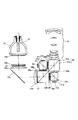
図1に、本発明の実施例1における画像投射装置の構成例を示す。
図1において、1は連続スペクトルで白色光を発光する光源、2は光を所定の方向に集光するリフレクター、3aは矩形のレンズをマトリックス状に配置した第1のフライアイレンズ、3bは第1のフライアイレンズにおける個々のレンズに対応したレンズアレイからなる第2のフライアイレンズある。
また、4は無偏光光を所定の偏光光に揃える偏光変換素子、5a,5bはコンデンサーレンズ、5cは反射ミラーである。また、6aはBの光の偏光方向を90度変換し、Rの光の偏光方向は変換しない第1の色選択性位相差板、6bはRの光の偏光方向を90度変換し、Bの光の偏光方向は変換しない第2の色選択性位相差板である。
【0012】
7は青(B)と赤(R)の波長領域の光を反射し、緑(G)の波長領域の光を透過するダイクロイックミラー、8aと8bはP偏光を透過し、S偏光を反射する第1の偏光ビームスプリッターと第2の偏光ビームスプリッターであり、13はGのP偏光光を透過し、RBのS偏光光を反射する色偏光合成プリズムである。
また、9r、9g、9bは光を反射し、画像変調して画像を表示する赤用の反射型液晶表示素子、緑用の反射型液晶表示素子、青用の反射型液晶表示素子、10r、10g、10bは赤用の1/4波長板、緑用の1/4波長板、青用の1/4波長板、11は投射レンズ、12a,12b,12c,12dはそれぞれ偏光板である。
【0013】
次に光学的な作用について説明する。光源1から発した光はリフレクター2により所定の方向に集光される。ここでリフレクター2は放物面形状をなしており、放物面の焦点位置からの光は放物面の対称軸に平行な光束となる。ただし、光源1は理想的な点光源ではなく有限の大きさを有しているので、集光する光束には放物面の対称軸に平行でない光の成分も多く含まれている。
これらの集光光束は第1のフライアイレンズ3aに入射する。第1のフライアイレンズ3aは外形が矩形の正の屈折力を有するレンズをマトリックス状に組み合わせて構成されており、入射した光束はそれぞれのレンズに応じた複数の光束に分割され、かつ集光され、第2のフライアイレンズ3bを経て、マトリックス状に複数の光源像を偏光変換素子の近傍に形成する。
偏光変換素子4は偏光分離面と反射面と1/2波長板からなり、マトリックス状に集光する複数の光束はその列に対応した偏光分離面に入射し、透過するP偏光成分の光と反射するS偏光成分の光に分割される。
【0014】
反射されたS偏光成分の光は反射面で反射し、P偏光成分と同じ方向に出射し、P偏光成分は1/2波長板を透過しS偏光成分と同じ偏光成分に変換され、偏光方向が揃った光として射出する。偏光変換された複数の光束は偏光変換素子の近傍で集光した後、発散光束として集光光学系に至る。
集光光学系は、コンデンサーレンズ5a、5bからなる。複数の光束は集光光学系によりフライアイレンズの矩形形状の像ができる位置でそれぞれ重なり、矩形の均一な照明エリアを形成する。この照明エリアに反射型液晶表示素子9r、9g、9bを配置する。
【0015】
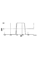
照明光路中に設けられたダイクロミラー7は図2の実線で示すような特性を有している。
ダイクロミラー7において色分離されたGの光は、偏光板12aによりダイクロミラーなどによる偏光の乱れを整えられた後、第1の偏光ビームスプリッター8aに対してS偏光として入射し、偏光分離面を反射し、G用の反射型液晶表示素子9gへと至る。
G用の反射型液晶表示素子9gにおいてGの光が画像変調されて反射される。画像変調されたGの反射光のS偏光成分は再び偏光分離面を反射し、光源側に戻され投射光から除去される。画像変調されたGの反射光のP偏光成分は偏光分離面を透過し投射光となる。
【0016】
第1の偏光ビームスプリッター8aを透過した光は、偏光板12bでさらに不要な偏光成分を除去されて、色偏光合成プリズム13へと至る。
ダイクロイックミラー7を反射したRとBの光は、偏光板12cによりダイクロイックミラーなどによる偏光の乱れを整えられた後、第1の色選択性位相差板6aに入射する。第1の色選択性位相差板6aの特性を図3に示す。
図3は入射する光の偏光方向に対して90度(直交する)方向に偏光方向が変換される変換率を表わしており,これによりRの光は変換されずS偏光のままで、Bの光は変換されてP偏光になる。
これによりBの光はP偏光として、Rの光はS偏光として第2の偏光ビームスプリッター8bに入射する。よって第2の偏光ビームスプリッター8bにおいてBの光は偏光分離面を透過してB用の反射型液晶表示素子9bに至り、Rの光は偏光分離面を反射してR用の反射型液晶表示素子9rに至る。
【0017】
B用の反射型液晶表示素子9bにおいてBの光が画像変調されて反射される。
変調されたBの反射光のP偏光成分は再び偏光分離面を透過し、光源側に戻され投射光から除去される。変調されたBの反射光のS偏光成分は第2の偏光ビームスプリッター8bの偏光分離面で反射し色偏光合成プリズム13へと至る。同様にR用の反射型液晶表示素子9rにおいてRの光が画像変調されて反射される。
変調されたRの反射光のS偏光成分は再び偏光分離面を反射し、光源側に戻され投射光から除去される。変調されたRの反射光のP偏光成分は偏光ビームスプリッター8bの偏光分離面を透過し、BとRの投射光は一つの光束に合成される
。
【0018】
合成されたRとBの投射光は第2の色選択性位相差板6bに入射する。第2の色選択性位相差板は図4に示すような特性を有しており、Bの光はS偏光のままで、Rの光はS偏光に変換され、偏光板12dでさらに不要な偏光成分を除去されて、色偏光合成プリズム13にS偏光として入射し、色偏光合成膜を反射することで色偏光合成膜を透過したP偏光のGの投射光と合成される。
合成されたRGBの投射光は投射レンズ11によりスクリーンなどに投影される。
【0019】
本実施例における色偏光合成プリズム13は2つの三角プリズム13a、13bを接合する構成でできており、一方の三角プリズム13aの接合面に色偏光合成膜を設け、もう一方の三角プリズム13bと接着剤により接合している。
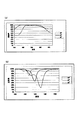
ここで、表1に本実施例に用いる色偏光合成膜の設計例を示す。図5a,図5bはその特性図である。図5aには偏光分離膜に入射する角度が40,45,50度のときのP偏光の透過率、図5bには偏光分離膜に入射する角度が40,45,50度のときのS偏光の透過率を示している。
【0020】
【表1】
このとき緑(G)の波長範囲を500〜570nm、赤(R)の波長範囲を590〜650nm、青(B)の波長範囲を430〜480nmとするとき、基準の入射角度45度に対して所定の角度範囲(±5度)における平均透過率、平均反射率を求めると、
ここで所定の角度範囲の平均透過率は、入射角度45度におけるGの波長範囲に対する平均透過率をTpg45とし、±5度のGの波長範囲に対する平均透過率をTpg40,Tpg50とするとき、
Tpg=(Tpg40+Tpg45+Tpg50)/3
で求められる。他の波長範囲および反射率も同様にして求める。
これよりGの波長範囲におけるP偏光の平均透過率は、
Tpg=94.7%>90%
Rの波長範囲においてS偏光の平均反射率は、
Rsr=97.2%>90%
Bの波長範囲においてS偏光の平均反射率は、
Rsb=96.7%>90%
である。
【0021】
この膜構成において屈折率の高い材質の屈折率nHが2.3で屈折率が低い材質の屈折率nLが1.46であるので、膜に対して45度で入射する光がブリュースター角となるようにプリズムのガラスの屈折率nBをもとめると、
nB=√(2×nH2+nL2/(nH2+nL2))=1.74
となるが、ここでは基板の屈折率として1.52のガラスを用いているので、P偏光の光に対してはブリュースター条件を満足していないが、Gの波長範囲に対してのみ低反射特性が得られるような膜構成となっている。
また、膜構成は屈折率の高い材質と屈折率が低い材質の交互層になっているが、繰り返される膜厚をそれぞれ異なる膜厚になるように構成することで,交互層の周期性を低減させ、反射帯と透過帯が交互に発生しないようにしている。
これにより角度特性に左右されない高効率の透過率と反射率を所定の波長範囲で得ている。
【0022】
ここで可視光の波長範囲を430〜650nmとすると、
可視光の波長範囲におけるP偏光の平均透過率は、
Tpw=84.5%>75%
可視光の波長範囲におけるS偏光の平均反射率は、
Rsw=86.8%>75%
となり、大部分のP偏光光を透過し、S偏光光を反射する特性であるが、通常の偏光分離膜とは異なり、入射角度45度±5度の角度範囲において各波長範囲の特性は均一ではない。
【0023】
Gの波長範囲においてP偏光の平均反射率は、
Rpg=2.6%
Rの波長範囲においてP偏光の平均反射率は、
Rpr=25.9%
Bの波長範囲においてP偏光の平均反射率は、
Rpb=23.6%
Gの波長範囲におけるS偏光の平均透過率は、
Tsg=30.4%
Rの波長範囲におけるS偏光の平均透過率は、
Tsr=2.8%
Bの波長範囲におけるS偏光の平均透過率は、
Tsb=3.3%
となる。
【0024】
R,Bの波長範囲のP偏光の平均反射率に対するGの波長範囲のP偏光の平均反射率の比は、
Rpg/Rpr=0.099<0.5
Rpg/Rpb=0.108<0.5
Gの波長範囲のS偏光の平均透過率に対するR,Bの波長範囲のS偏光の平均透過率の比は、
Tsr/Tsg=0.091<0.5
Tsb/Tsg=0.108<0.5
であり、色合成として利用する波長範囲のみを高効率になるように膜特性を設定することで、角度変動を少なくできている。
【0025】
[実施例2]
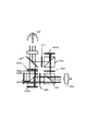
図6に、本発明の実施例2における画像投射装置の構成例を示す。
図6において、21は連続スペクトルで白色光を発光する光源、22は光を所定の方向に集光するリフレクター、23aは矩形のレンズをマトリックス状に配置した第1のフライアイレンズ、23bは第1のフライアイレンズの個々のレンズに対応したレンズアレイからなる第2のフライアイレンズであり、24は無偏光光を所定の偏光光に揃える偏光変換素子、25a,25bはコンデンサーレンズ、25cは反射ミラーである。
また、26aはBの光の偏光方向を90度変換し、Rの光の偏光方向は変換しない第1の色選択性位相差板で、26bはRの光の偏光方向を90度変換し、Bの光の偏光方向は変換しない第2の色選択性位相差板で、27はGの光の偏光方向を90度変換し、B,Rの光の偏光方向は変換しない第3の色選択性位相差板である。
【0026】
28は1/2位相板であり、29a、29b、29cはP偏光を透過し、S偏光を反射する第1の偏光ビームスプリッター、第2の偏光ビームスプリッター、第3の偏光ビームスプリッターである。
また、34はGのP偏光光を透過し、RBのS偏光光を反射する色偏光合成プリズムであり、30r、30g、30bは光を反射し、画像変調して画像を表示する赤用の反射型液晶表示素子、緑用の反射型液晶表示素子、青用の反射型液晶表示素子である。
31r、31g、31bは赤用の1/4波長板、緑用の1/4波長板、青用の1/4波長板であり、32は投射レンズ、33a,33b,33c,33dはそれぞれ偏光板である。
【0027】
ここで偏光変換素子24は偏光分離面と反射面と1/2波長板からなりS偏光成分に揃った偏光光として射出する構成としている。照明光路中に設けられた第3の色選択性位相差板27は図7の実線で示すような特性を有しており、BとRの光はS偏光のままで、Gの光はP偏光に変換される。
第3の色選択性位相差板27において偏光方向を調整された光は第1の偏光ビームスプリッター29aに入射する。P偏光であるGの光は偏光分離面を透過し、S偏光であるR,Bの光は偏光面を反射することで色分離が行われる。
【0028】
色分離されたGの光は、1/2位相板28により偏光方向を変換され,偏光板33aにより変更を整えられたのち、第2の偏光ビームスプリッター29bに対してS偏光として入射し、偏光分離面を反射し、G用の反射型液晶表示素子30gへと至る。
G用の反射型液晶表示素子30gにおいてGの光が画像変調されて反射される。画像変調されたGの反射光のS偏光成分は再び偏光分離面を反射し、光源側に戻され投射光から除去される。
画像変調されたGの反射光のP偏光成分は第2の偏光ビームスプリッターの偏光分離面を透過し、偏光板33bによりさらに不要な偏光成分を除去されて、色偏光合成プリズムに対してP偏光として入射し、色偏光合成面を透過し、投射レンズ32へと至る。
【0029】
第1の偏光ビームスプリッター28aを反射したRとBの光は、第1の色選択性位相差板26aに入射する。第1の色選択性位相差板26aは図3で示したような特性を有しており、Rの光はP偏光のままで、Bの光はS偏光に変換される。
これによりBの光はP偏光として、Rの光はS偏光として第3の偏光ビームスプリッター29cに入射する。よって第3の偏光ビームスプリッター29cにおいてBの光は偏光分離面を透過してB用の反射型液晶表示素子30bに至り、Rの光は偏光分離面を反射してR用の反射型液晶表示素子30rに至る。
【0030】
B用の反射型液晶表示素子30bにおいてBの光が画像変調されて反射される。変調されたBの反射光のP偏光成分は再び偏光分離面を透過し、光源側に戻され投射光から除去される。
変調されたBの反射光のS偏光成分は偏光分離面で反射し投射光となる。同様にR用の反射型液晶表示素子30rにおいてRの光が画像変調されて反射される。変調されたRの反射光のS偏光成分は再び偏光分離面を反射し、光源側に戻され投射光から除去される。変調されたRの反射光のP偏光成分は偏光分離面を透過し投射光となる。これによりBとRの投射光は一つの光束に合成される。
【0031】
合成されたRとBの投射光は第2の色選択性位相差板26bに入射する。第2の色選択性位相差板は図4で示したような特性を有しており、Rの偏光方向のみを90度回転し、R、BともにS偏光に変換され、色偏光合成プリズムに至り、色偏光合成面を反射することでGの投射光と合成される。
【0032】
本実施例における色偏光合成プリズム34は2つの三角プリズム34a、34bを接合する構成でできており、一方の三角プリズム34aの接合面に色偏光合成膜を設け、もう一方の三角プリズム34bと接着剤により接合している。
ここで、表2に本実施例に用いる色偏光合成膜の設計例を示す。図8a,8bはその特性図である。図8aには偏光分離膜に入射する角度が40,45,50度のときのP偏光の透過率、図8bには偏光分離膜に入射する角度が40,45,50度のときのS偏光の透過率を示している。
【0033】
【表2】
ここで、接着剤の屈折率が1.51で、基板の屈折率が1.61であるので接着剤と三角プリズム34bの接合面においてフレネル反射が発生し光量がわずかに損失するので、三角プリズム34bの接合面に反射防止膜を設けて色偏光合成膜と反射防止膜を接着剤で接合する構成でもよい。
【0034】
色偏光合成膜の特性は、緑(G)の波長範囲を500〜570nm、赤(R)の波長範囲を590〜650nm、青(B)の波長範囲を430〜480nmとするとき、
Gの範囲におけるP偏光の平均透過率は、
Tpg=99.0%>90%
Rの波長範囲においてS偏光の平均反射率は、
Rsr=98.2%>90%
Bの波長範囲においてS偏光の平均反射率は、
Rsb=97.8%>90%
である。
【0035】
ここで可視光の波長範囲を430〜650nmとすると、
可視光の波長範囲におけるP偏光の平均透過率は、
Tpw=90.7%>75%
可視光の波長範囲におけるS偏光の平均反射率は、
Rsw=90.3%>75%
となり、大部分のP偏光光を透過し、S偏光光を反射する特性であるが、通常の偏光分離膜とは異なり、入射角度45度±5度の角度範囲において各波長範囲の特性は均一ではない。
【0036】
Gの波長範囲においてP偏光の平均反射率は、
Rpg=1.0%
Rの波長範囲においてP偏光の平均反射率は、
Rpr=14.4%
Bの波長範囲においてP偏光の平均反射率は、
Rpb=16.4%
Gの波長範囲におけるS偏光の平均透過率は、
Tsg=22.6%
Rの波長範囲におけるS偏光の平均透過率は、
Tsr=1.8%
Bの波長範囲におけるS偏光の平均透過率は、
Tsb=2.2%
となる。
【0037】
また、R,Bの波長範囲のP偏光の平均反射率に対するGの波長範囲のP偏光の平均反射率の比は、
Rpg/Rpr=0.073<0.5
Rpg/Rpb=0.064<0.5
Gの波長範囲のS偏光の平均透過率に対するR,Bの波長範囲のS偏光の平均透過率の比は、
Tsr/Tsg=0.080<0.5
Tsb/Tsg=0.097<0.5
である。
【0038】
[実施例3]
表3は本発明の実施例3における実施例1または実施例2に用いる色偏光合成プリズム13または34における色偏光合成膜の設計例で、図9a,9bはその特性図である。図9aには偏光分離膜に入射する角度が40,45,50度のときのP偏光の透過率、図9bには偏光分離膜に入射する角度が40,45,50度のときのS偏光の透過率を示している。
【0039】
【表3】
緑(G)の波長範囲を500〜570nm、赤(R)の波長範囲を590〜650nm、青(B)の波長範囲を430〜480nmとするとき、
Gの範囲におけるP偏光の平均透過率は、
Tpg=96.6%>90%
Rの波長範囲においてS偏光の平均反射率は、
Rsr=97.8%>90%
Bの波長範囲においてS偏光の平均反射率は、
Rsb=97.5%>90%
である。
【0040】
本実施例では色偏光合成プリズムを構成するガラスの屈折率はブリュースターをほぼ満足する屈折率となるが、あえて膜厚を狭帯域の反射防止になるように調整することにより実施例1、実施例2と同様な効果が得られている。このとき、設計としては基準となる入射角度(45度)からずれた入射角度(40,50度)において狭帯域の反射防止になるように調整する。
ここで、可視光の波長範囲を430〜650nmとすると、可視光の波長範囲におけるP偏光の平均透過率は、
Tpw=92.2%>75%
可視光の波長範囲におけるS偏光の平均反射率は、
Rsw=94.6%>75%
となり、大部分のP偏光光を透過し、S偏光光を反射する特性であるが、通常の偏光分離膜とは異なり、入射角度45度±5度の角度範囲において各波長範囲の特性は均一ではない。
【0041】
Gの波長範囲においてP偏光の平均反射率は、
Rpg=3.4%
Rの波長範囲においてP偏光の平均反射率は、
Rpr=7.7%
Bの波長範囲においてP偏光の平均反射率は、
Rpb=14.3%
Gの波長範囲におけるS偏光の平均透過率は、
Tsg=10.5%
Rの波長範囲におけるS偏光の平均透過率は、
Tsr=2.2%
Bの波長範囲におけるS偏光の平均透過率は、
Tsb=2.5%
となる。
また、R,Bの波長範囲のP偏光の平均反射率に対するGの波長範囲のP偏光の平均反射率の比は、
Rpg/Rpr=0.441<0.5
Rpg/Rpb=0.236<0.5
Gの波長範囲のS偏光の平均透過率に対するR,Bの波長範囲のS偏光の平均透過率の比は、
Tsr/Tsg=0.204<0.5
Tsb/Tsg=0.234<0.5
である。
【0042】
[実施例4]
表4は、本発明の実施例4における実施例1または実施例2に用いる色偏光合成プリズム13または34における色偏光合成膜の設計例である。
これまでに示した本発明による色偏光合成膜の実施例は、2種類の材質の薄膜を積層する構造であるが、さらに本実施例のように多数の種類の材料を用いても本発明の効果を得ることができる。
【0043】
【表4】
図10a,図10bはその特性図である。図10aには偏光分離膜に入射する角度が40,45,50度のときのP偏光の透過率、図10bには偏光分離膜に入射する角度が40,45,50度のときのS偏光の透過率を示している。
緑(G)の波長範囲を500〜570nm、赤(R)の波長範囲を590〜650nm、青(B)の波長範囲を430〜480nmとするとき、Gの範囲におけるP偏光の平均透過率は、
Tpg=99.6%>90%
Rの波長範囲においてS偏光の平均反射率は、
Rsr=98.2%>90%
Bの波長範囲においてS偏光の平均反射率は、
Rsb=98.0%>90%
である。
【0044】
可視光の波長範囲におけるP偏光の平均透過率は、
Tpw=87.7%>75%
可視光の波長範囲におけるS偏光の平均反射率は、
Rsw=84.5%>75%
となり、大部分のP偏光光を透過し、S偏光光を反射する特性であるが、通常の偏光分離膜とは異なり、入射角度45度±5度の角度範囲において各波長範囲の特性は均一ではない。
【0045】
Gの波長範囲においてP偏光の平均反射率は、
Rpg=0.4%
Rの波長範囲においてP偏光の平均反射率は、
Rpr=18.9%
Bの波長範囲においてP偏光の平均反射率は、
Rpb=23.7%
Gの波長範囲におけるS偏光の平均透過率は、
Tsg=35.4%
Rの波長範囲におけるS偏光の平均透過率は、
Tsr=1.8%
Bの波長範囲におけるS偏光の平均透過率は、
Tsb=2.0%
となる。
【0046】
また、R,Bの波長範囲のP偏光の平均反射率に対するGの波長範囲のP偏光の平均反射率の比は、
Rpg/Rpr=0.023<0.5
Rpg/Rpb=0.018<0.5
Gの波長範囲のS偏光の平均透過率に対するR,Bの波長範囲のS偏光の平均透過率の比は、
Tsr/Tsg=0.051<0.5
Tsb/Tsg=0.057<0.5
である。
【0047】
実施例1、実施例2に示した光学系と色偏光合成プリズムの膜構成は、この組合せに限られるものではなく、ここで示した光学系以外にもGのP偏光光とRBのS偏光光を1つの反射面で合成する色合成系において用いることもできる。
また、色偏光合成プリズムの膜構成も実施例3、実施例4に示した膜構成も含めて組み合わせることが可能である。
また、色偏光合成膜も本発明で示した数値条件を満足する特性の色偏光合成膜を用いれば、ここに示した膜設計値に限定されるものではなく、それ以外においても同様な効果が得られる。
また、GのS偏光光とRBのP偏光光を1つの反射面で合成する色合成系では、ここまでに示した透過と反射の関係を逆にした膜特性の色偏光合成膜を用いればよい。
【0048】
[実施例5]
表5は、本発明の実施例5の色偏光合成膜の設計例である。
これまでに示した本発明による色偏光合成膜の実施例は、Gの光を透過し、マゼンダの光を反射する構成であったが,さらに本実施例のようにGの光を反射し、マゼンダの光を透過する構成を用いても本発明の効果を得ることができる。
【0049】
【表5】
図15a,図15bはその特性図である。図15aには偏光分離膜に入射する角度が40,45,50度のときのP偏光の透過率、図15bには偏光分離膜に入射する角度が40,45,50度のときのS偏光の透過率を示している。
緑(G)の波長範囲を500〜570nm、赤(R)の波長範囲を590〜650nm、青(B)の波長範囲を430〜480nmとするとき、Gの範囲におけるS偏光の平均透過率は、
Rsg=99.7%>90%
Rの波長範囲においてS偏光の平均反射率は、
Tpr=99.3%>90%
Bの波長範囲においてS偏光の平均反射率は、
Tpb=99.1%>90%
である。
【0050】
Gの波長範囲においてP偏光の平均反射率は、
Rpg=30.8%
Rの波長範囲においてP偏光の平均反射率は、
Rpr=0.7%
Bの波長範囲においてP偏光の平均反射率は、
Rpb=0.9%
Gの波長範囲におけるS偏光の平均透過率は、
Tsg=0.3%
Rの波長範囲におけるS偏光の平均透過率は、
Tsr=51.9%
Bの波長範囲におけるS偏光の平均透過率は、
Tsb=61.8%
となる。
【0051】
また、R,Bの波長範囲のP偏光の平均反射率に対するGの波長範囲のP偏光の平均反射率の比は、
Rpr/Rpg=0.022<0.5
Rpb/Rpg=0.029<0.5
Gの波長範囲のS偏光の平均透過率に対するR,Bの波長範囲のS偏光の平均透過率の比は、
Tsg/Tsr=0.004<0.5
Tsg/Tsb=0.005<0.5
である。
【0052】
ただし、
可視光の波長範囲におけるP偏光の平均透過率は、
Tpw=67.2%
可視光の波長範囲におけるS偏光の平均反射率は、
Rsw=88.0
となり、P偏光光において偏光分離の割合が低くなっている。このため若干ダイクロイック特性が残存し角度により反射、透過の範囲が変動が起きているが変動範囲が狭いので効率よい色合成が可能である。
【0053】
本願発明の実施の態様は以下のように書き表すことができる。
【実施態様1】少なくとも2つの異なる色光を合成する色合成光学系であって、該色合成光学系は色偏光合成手段を含み、該色偏光合成手段が、第1の色光の第1の偏光成分と、該第1の偏光成分に略直交する前記第1の色光とは異なる第2の色光の第2の偏光成分を、所定の入射角度範囲において入射角度による特性の変動を抑制して合成する構成を有することを特徴とする色合成光学系。
【実施態様2】前記色偏光合成手段は、前記少なくとも2つの異なる色光を90%以上の効率で合成することを特徴とする実施態様1に記載の色合成光学系。
【実施態様3】前記色偏光合成手段は、色偏光合成面を有し、前記色偏光合成面には薄膜からなる色偏光合成膜が設けられていることを特徴とする実施態様1または実施態様2に記載の色合成光学系。
【実施態様4】前記第1の色光と第2の色光が入射する所定の角度範囲は、前記色偏光合成面に対して±5度であることを特徴とする実施態様1〜3のいずれか1項に記載の色合成光学系。
【実施態様5】前記色合成手段は、少なくとも2つの画像表示素子と、該画像表示素子からの光を検光する検光手段と、色合成手段により色合成した光を拡大投射する画像投射手段とを有し、これらを前記画像表示素子から、検光手段、色偏光合成手段、画像投射手段の順に配して構成されていることを特徴とする実施態様1〜4のいずれか1項に記載の色合成光学系。
【実施態様6】前記検光手段は、第1の検光手段と第2の検光手段を有し、画像表示素子から、第1の検光手段、第2の検光手段の順に配して構成されていることを特徴とする実施態様5に記載の色合成光学系。
【実施態様7】前記色偏光合成手段は、プリズムで構成され、該プリズム内に設けられた1つの面で色合成することを特徴とする実施態様1〜6のいずれか1項に記載の色合成光学系。
【実施態様8】前記第1の色光は緑で、第2の色光はマゼンタであることを特徴とする実施態様1〜7のいずれか1項に記載の色合成光学系。
【実施態様9】前記第1の偏光成分は色偏光合成面に対してP偏光であり、前記第2の偏光成分は色偏光合成面に対してS偏光であることを特徴とする実施態様1〜8のいずれか1項に記載の色合成光学系。
【実施態様10】前記第1の偏光成分は色偏光合成面に対してS偏光であり、前記第2の偏光成分は色偏光合成面に対してP偏光であることを特徴とする実施態様1〜8のいずれか1項に記載の色合成光学系。
【実施態様11】前記色合成手段は、第1、第2及び第3の画像表示素子を有し、前記第1の画像表示素子からの光は、第1の検光手段、色偏光合成プリズム、画像投射手段を経て投射され、前記第2及び第3の画像表示素子からの光は色合成プリズム、第2の検光手段、色偏光合成プリズム、画像投射手段を経て投射されることを特徴とする実施態様1〜10のいずれか1項に記載の色合成光学系。
【実施態様12】前記色合成プリズムと前記第2の検光手段は、一つの偏光ビームスプリッターからなり、偏光ビームスプリッターと色偏光合成プリズムの間に色選択性位相差板を設けることを特徴とする実施態様11に記載の色合成光学系。
【実施態様13】前記第1の検光手段は第1の偏光ビームスプリッターと第1の偏光板からなり、前記色合成プリズムと前記第2の検光手段は第2の偏光ビームスプリッターからなり、前記第2の偏光ビームスプリッターと前記色偏光合成プリズムの間には色選択性位相差板を設け、色選択性位相差板と色偏光合成プリズムの間には第2の偏光板を設けることを特徴とする実施態様11に記載の色合成光学系。
【実施態様14】第1の偏光ビームスプリッターと第2の偏光ビームスプリッターには、同じ偏光分離膜が設けられていることを特徴とする実施態様13に記載の色合成光学系。
【実施態様15】前記第1の色光は500〜570nmの第1の波長範囲からなり、前記第2の色光は430〜480nmの第2の波長範囲と590〜650nmの第3の波長範囲からなることを特徴とする実施態様11〜14のいずれか1項に記載の色合成光学系。
【実施態様16】前記色偏光合成膜に入射する光の入射角度を45度±5度としたとき、該色偏光合成膜における前記第1の波長範囲の透過率が90%以上であり、前記第2及び前記第3の波長範囲の反射率が90%以上であることを特徴とする実施態様15に記載の色合成光学系。
【実施態様17】前記色偏光合成膜が、前記所定の入射角度で入射する可視の波長範囲の光のP偏光を65%以上透過し、S偏光を65%以上反射する特性で、かつ、前記第1の波長範囲におけるP偏光の平均反射率をRp1、前記第2の波長範囲におけるP偏光の平均反射率をRp2、前記第3の波長範囲におけるP偏光の平均反射率をRp3とするとき、
Rp1/Rp2<0.5
Rp1/Rp3<0.5
とし、
前記第1の波長範囲におけるS偏光の平均透過率をTs1、前記第2の波長範囲におけるS偏光の平均透過率をTsr、前記第3の波長範囲におけるS偏光の平均透過率をTsbとするとき、R,Bの波長範囲のP偏光の平均反射率に対するGの波長範囲のP偏光の平均反射率の比が、
Ts2/Ts1<0.5
Ts3/Ts1<0.5
とする条件を満足することを特徴とする実施態様16に記載の色合成光学系。
【実施態様18】前記色偏光合成膜が、前記所定の入射角度で入射する可視の波長範囲の光のP偏光を75%以上透過する特性を有することを特徴とする実施態様17記載の色合成光学系。
【実施態様19】前記色偏光合成膜が、前記所定の入射角度で入射する可視の波長範囲の光のS偏光を75%以上反射する特性を有することを特徴とする実施態様17または実施態様18に記載の色合成光学系。
【実施態様20】前記色偏光合成膜に入射する光の入射角度を45度±5度としたとき該色偏光合成膜における前記第1の波長範囲の反射率が90%以上であり、前記第2及び前記第3の波長範囲の透過率が90%以上であることを特徴とする実施態様15に記載の色合成光学系。
【実施態様21】前記色偏光合成膜が、前記所定の入射角度で入射する光のP偏光を65%以上透過し、S偏光を65%以上反射する特性で、かつ、前記第1の波長範囲におけるP偏光の平均反射率をRp1、前記第2の波長範囲におけるP偏光の平均反射率をRp2、前記第3の波長範囲におけるP偏光の平均反射率をRp3とするとき、
Rp2/Rp1<0.5
Rp3/Rp1<0.5
とし、
前記第1の波長範囲におけるS偏光の平均透過率をTs1、前記第2の波長範囲におけるS偏光の平均透過率をTsr、前記第3の波長範囲におけるS偏光の平均透過率をTsbとするとき、R,Bの波長範囲のP偏光の平均反射率に対するGの波長範囲のP偏光の平均反射率の比が、
Ts1/Ts2<0.5
Ts1/Ts3<0.5
とする条件を満足することを特徴とする実施態様20に記載の色合成光学系。
【実施態様22】前記色偏光合成膜が、前記所定の入射角度で入射する可視の波長範囲の光のP偏光を75%以上透過する特性を有することを特徴とする実施態様21記載の色合成光学系。
【実施態様23】前記色偏光合成膜が、前記所定の入射角度で入射する可視の波長範囲の光のS偏光を75%以上反射する特性を有することを特徴とする実施態様21または実施態様22に記載の色合成光学系。
【実施態様24】光源と、該光源からの光を少なくとも2つの色光に分解する色分解手段と、少なくとも2つの画像表示素子、該画像表示素子からの異なる色光を合成する色偏光合成手段、該色偏光合成手段によって色合成した光を拡大投射する画像投射手段を有する色合成光学系と、を備えた画像投射装置において、
前記色合成光学系を実施態様1〜23のいずれか1項に記載の色合成光学系によって構成したことを特徴とする画像投射装置。
【実施態様25】光源と、光源からの光を少なくとも2つの色光に分解する色分解手段と、少なくとも2つの反射型の画像表示素子、該画像表示素子からの異なる色光を合成する色偏光合成手段、該色偏光合成手段によって色合成した光を拡大投射する画像投射手段を有する色合成光学系と、を備えた画像投射装置において、
前記色合成光学系を実施態様1〜23のいずれか1項に記載の色合成光学系によって構成したことを特徴とする画像投射装置。
【0054】
【発明の効果】
本発明によれば、色合成光学系において光量損失の低減化を図ることができ、また、それにより明るい画像投射装置を実現することが可能となる。
【図面の簡単な説明】
【図1】本発明の実施例1における画像投射装置の構成例を示す図。
【図2】本発明の実施例1のダイクロイックミラーを説明する図。
【図3】本発明の実施例1の色選択性位相差板を説明する図。
【図4】本発明の実施例1の色選択性位相差板を説明する図。
【図5】(a)、(b)は本発明の実施例1の色偏光合成プリズムを説明する図。
【図6】本発明の実施例2における画像投射装置の構成例を示す図。
【図7】本発明の実施例2における色選択性位相差板を説明する図。
【図8】(a)、(b)は本発明の実施例2の色偏光合成プリズムを説明する図。
【図9】(a)、(b)は本発明の実施例3の色偏光合成プリズムを説明する図。
【図10】(a)、(b)は本発明の実施例4の色偏光合成プリズムを説明する図。
【図11】従来例における画像投射装置の構成を説明する図。
【図12】従来例における偏光分離膜のP偏光の透過率特性を示す図。
【図13】従来例における偏光分離膜のS偏光の反射率特性を示す図。
【図14】従来例におけるダイクロ特性が波長方向にシフトして角度変動が起きてしまう状態を説明する図。
【図15】(a)、(b)は本発明の実施例5の色偏光合成プリズムを説明する図。
【符号の説明】
1:光源
2:リフレクター
3a:第1のフライアイレンズ
3b:第2のフライアイレンズ
4:偏光変換素子
5a,5b:コンデンサーレンズ
5c:反射ミラー
6a:第1の色選択性位相差板
6b:第2の色選択性位相差板
7:ダイクロイックミラー
8a:第1の偏光ビームスプリッター
8b:第2の偏光ビームスプリッター
13:色偏光合成プリズム
9r、9g、9b:反射型液晶表示素子
10r、10g、10b:1/4波長板
11:投射レンズ
12a、12b、12c、12d:偏光板
21:光源
22:リフレクター
23a:第1のフライアイレンズ
23b:第2のフライアイレンズ
24:偏光変換素子
25a,5b:コンデンサーレンズ
25c:反射ミラー
26a:第1の色選択性位相差板
26b:第2の色選択性位相差板
27:第3の色選択性位相差板
28:1/2位相板
29a:第1の偏光ビームスプリッター
29b:第1の偏光ビームスプリッター
29c:第1の偏光ビームスプリッター
30r、30g、30b:反射型液晶表示素子
31r、31g、31b:1/4波長板
32:投射レンズ
33a、33b、33c:偏光板
34:色偏光合成プリズム[0001]
TECHNICAL FIELD OF THE INVENTION
The present invention relates to a color synthesizing optical system, and more particularly, to a color synthesizing optical system capable of reducing a light amount loss in color synthesizing, and an image projection apparatus and the like using the same.
[0002]
[Prior art]
An image projection apparatus combining a reflection type liquid crystal display element and a polarizing beam splitter in a conventional example is disclosed in Patent Document 1 and the like.
This patent document 1 discloses an image projection apparatus including a white light source 1001, reflection type liquid crystal display elements 1002R, 1002G, 1002B and a projection optical system 1003 as shown in FIG. A dichroic mirror 1004 is provided between 1002G and 1002B. Further, a color separation system in which polarization beam splitters 1005 and 1006 are provided between the dichroic mirror 1004 and the reflection type liquid crystal display elements 1002R, 1002G and 1002B, and a first and second color separation system between the reflection type liquid crystal display element and the projection optical system. , A third color beam splitter 1005, 1006, 1007.
[0003]
Here, the color separation system is separated into a first color light (G) and a second third color light (RB) by a dichroic mirror 1004, and the first color light reaches a first polarization beam splitter 1005. Further, the second and third color lights can rotate the polarization direction of light in a predetermined wavelength region provided between the dichroic mirror 1004 and the second polarization beam splitter 1006 by 90 degrees. The color component (R, B) and the polarization direction (P, S) are associated with each other by the neutral phase difference plate 1008. Then, the polarization direction of the B color light is rotated by 90 degrees by the first color-selective phase difference plate 1008, and the B color light is converted into the P-polarized light and the R color light as the S-polarized light. The incident light is split into a second color light (R) and a third color light (B) as color separation in a polarization beam splitter.
[0004]
In the color synthesis system, the light reflected by the first polarization beam splitter 1005 is reflected by rotating the polarization direction by 90 degrees by the first reflection type liquid crystal display element 1002G, and is transmitted through the first polarization beam splitter 1005. , The polarization direction is rotated by 90 degrees by the 位相 phase plate 1012, and reflected by the third polarization beam splitter 1007 to reach the projection optical system 1003. The light in the second optical path is reflected by rotating the polarization direction by 90 degrees in the second reflective liquid crystal display element 1002R, passes through the second polarization beam splitter 1006, and the light in the third optical path is the third light. The reflection type liquid crystal display device 1002B rotates the polarization direction by 90 degrees and reflects the light, reflects the second polarization beam splitter 1006, and combines the two color lights (R and B) into one optical path. Then, the polarization direction of the B color light is rotated by 90 degrees by the second color-selective phase difference plate 1009 provided between the second polarization beam splitter 1006 and the third polarization beam splitter 1007, and the R, B Both the color lights become P-polarized light, and are transmitted through the third polarization beam splitter 1007 to reach the projection optical system 1003 so that the three color lights are combined.
[Patent Document 1] JP-A-2001-154268
[0005]
[Problems to be solved by the invention]
However, since the polarizing beam splitter is used as the color combining means for combining the first color light and the second third color light in the color combining system of the image projection apparatus as shown in the conventional example, it is provided in the polarizing beam splitter. Due to the incident angle characteristic of the polarized light separating film, the transmittance of P-polarized light is reduced, and there is a problem that the loss of light amount and the color balance are lost.
FIG. 12 shows the transmittance characteristics of the P-polarized light of the polarization separation film. Since the polarized light separating film obtains a transmittance close to 100% when the P-polarized light transmitted through the polarized light separating film satisfies the Brewster angle, when the incident angle fluctuates, the incident angle in the polarized light separating film deviates from the Brewster angle. Will be. As a result, the transmittance is greatly reduced, so that there is a problem that an angle variation as shown in FIG. 12 occurs.
[0006]
Further, in the conventional example, a dichroic prism is used as a color combining means instead of the polarization beam splitter 1007. In this case, however, the half-value wavelength for separating the transmission and reflection wavelengths is shifted by the incident angle characteristic, and the spectral characteristic is reduced. Will change. As a result, there is a problem that the light amount is lost and the color balance is lost.
FIG. 13 shows the S-polarized light reflectance characteristics of the polarized light separating film. The dichroic film is composed of alternating layers with different refractive indices, and has the same equivalent refractive index, so that a transmission (wavelength) band transmitting light and a reflection (wavelength) band reflecting light are generated alternately. Thus, a dichroic characteristic that transmits a specific wavelength band and reflects other wavelength bands is obtained.
[0007]
At this time, the center wavelength λ0 of the reflection band is determined by the refractive index n and the film thickness d of the film material forming the alternating layers and the ray angle θ with respect to the refractive surface as shown in FIG.
λ0 = 4 × n1 × d1 × cos (θ1) = 4 × n2 × d2 × cos (θ2)
Holds.
here
n1 × d1 × cos (θ1), n2 × d2 × cos (θ2)
Is the equivalent film thickness.
When the incident angle changes and the ray angle θ with respect to the refraction surface changes, the center wavelength of the reflection band changes, so that the dichroic characteristic shifts in the wavelength direction and the angle fluctuation as shown in FIG. 13 occurs.
[0008]
Therefore, an object of the present invention is to provide an image projection apparatus and the like that can reduce the amount of light due to a change in the incident angle and combine the images to thereby obtain a bright image. .
[0009]
[Means for Solving the Problems]
The present invention provides a color combining optical system including a color / polarization combining unit that combines at least two different color lights, wherein the color / polarization combining unit includes a first polarization component of the first color light and a first polarization component of the first color component. A second polarization component of a second color light different from the first color light orthogonal to the first color light is combined at a specific incidence angle range with a variation in characteristics due to an incident angle suppressed, and specifically, an efficiency of 90% or more. Thus, the loss of light amount in color synthesis is reduced, and a bright image projection device or the like can be provided.
[0010]
BEST MODE FOR CARRYING OUT THE INVENTION
Embodiments of the present invention will be described with reference to the following examples.
[0011]
【Example】
[Example 1]
FIG. 1 illustrates a configuration example of an image projection apparatus according to a first embodiment of the present invention.
In FIG. 1, 1 is a light source that emits white light in a continuous spectrum, 2 is a reflector that collects light in a predetermined direction, 3a is a first fly-eye lens in which rectangular lenses are arranged in a matrix, and 3b is a first fly-eye lens. There is a second fly-eye lens comprising a lens array corresponding to each lens in one fly-eye lens.
Reference numeral 4 denotes a polarization conversion element for converting unpolarized light into predetermined polarized light, 5a and 5b denote condenser lenses, and 5c denotes a reflection mirror. Further, 6a converts the polarization direction of the B light by 90 degrees, and does not change the polarization direction of the R light. The first color-selective phase difference plate 6b converts the polarization direction of the R light by 90 degrees. Is a second color-selective phase difference plate that does not change the polarization direction of light.
[0012]
7 is a dichroic mirror that reflects light in the blue (B) and red (R) wavelength regions and transmits light in the green (G) wavelength region, and 8a and 8b transmit P-polarized light and reflect S-polarized light. A first polarization beam splitter and a second polarization beam splitter, and 13 is a color polarization combining prism that transmits G P-polarized light and reflects RB S-polarized light.
Reference numerals 9r, 9g, and 9b reflect light, modulate an image, and display an image by displaying a red reflective liquid crystal display element, a green reflective liquid crystal display element, a blue reflective liquid crystal display element, 10r, 10g and 10b are red quarter-wave plates, green quarter-wave plates, blue quarter-wave plates, 11 is a projection lens, and 12a, 12b, 12c and 12d are polarizing plates, respectively.
[0013]
Next, the optical function will be described. Light emitted from the light source 1 is collected by the reflector 2 in a predetermined direction. Here, the reflector 2 has a parabolic shape, and light from the focal position of the paraboloid becomes a light beam parallel to the symmetry axis of the paraboloid. However, since the light source 1 is not an ideal point light source but has a finite size, the light beam to be collected contains many light components that are not parallel to the symmetry axis of the paraboloid.
These condensed light beams enter the first fly-eye lens 3a. The first fly-eye lens 3a is configured by combining lenses having a rectangular shape and having a positive refractive power in a matrix, and the incident light beam is divided into a plurality of light beams corresponding to the respective lenses, and is condensed. Then, a plurality of light source images are formed in a matrix in the vicinity of the polarization conversion element via the second fly-eye lens 3b.
The polarization conversion element 4 includes a polarization separation surface, a reflection surface, and a half-wave plate, and a plurality of light beams condensed in a matrix form are incident on a polarization separation surface corresponding to the column, and are transmitted with P-polarized component light. It is split into reflected S-polarized light components.
[0014]
The reflected light of the S-polarized light component is reflected by the reflection surface and emitted in the same direction as the P-polarized light component. The P-polarized light component is transmitted through a half-wave plate and converted into the same polarized light component as the S-polarized light component. Emits as uniform light. The plurality of polarization-converted light fluxes are converged near the polarization conversion element, and then reach a converging optical system as divergent light fluxes.
The condensing optical system includes condenser lenses 5a and 5b. The plurality of light beams overlap each other at a position where a rectangular image of the fly-eye lens is formed by the condensing optical system, and form a rectangular uniform illumination area. The reflection type liquid crystal display elements 9r, 9g, 9b are arranged in this illumination area.
[0015]
The dichroic mirror 7 provided in the illumination light path has characteristics as shown by a solid line in FIG.
The G light that has been color-separated by the dichroic mirror 7 is adjusted to have polarization disorder by a dichroic mirror or the like by the polarizing plate 12a, and then enters the first polarization beam splitter 8a as S-polarized light, and the polarization separation surface is deflected. The light is reflected and reaches the reflective liquid crystal display element 9g for G.
The G light is image-modulated and reflected by the G reflective liquid crystal display element 9g. The S-polarized component of the image-modulated G reflected light reflects off the polarization splitting surface again, returns to the light source side, and is removed from the projected light. The P-polarized component of the image-modulated G reflected light passes through the polarization splitting surface and becomes projection light.
[0016]
The light transmitted through the first polarization beam splitter 8a is further removed of unnecessary polarization components by the polarization plate 12b, and reaches the color / polarization combining prism 13.
The R and B lights reflected by the dichroic mirror 7 are incident on the first color-selective phase difference plate 6a after the polarization disorder is adjusted by the dichroic mirror and the like by the polarizing plate 12c. FIG. 3 shows the characteristics of the first color-selective phase difference plate 6a.
FIG. 3 shows the conversion rate at which the polarization direction is changed in a direction of 90 degrees (perpendicular to) the polarization direction of the incident light, whereby the R light is not converted, the S light remains unchanged, and the B light is converted. The light is converted to P-polarized light.
As a result, the B light enters the second polarization beam splitter 8b as P-polarized light and the R light enters as S-polarized light. Accordingly, in the second polarization beam splitter 8b, the B light passes through the polarization splitting surface and reaches the reflective liquid crystal display element 9b for B, and the R light reflects on the polarization splitting surface and reflects on the reflective liquid crystal display device for R. It reaches element 9r.
[0017]
The B light is image-modulated and reflected by the B reflective liquid crystal display element 9b.
The modulated P-polarized light component of the reflected B light passes through the polarization splitting surface again, returns to the light source side, and is removed from the projected light. The modulated S-polarized component of the reflected light of B is reflected by the polarization splitting surface of the second polarization beam splitter 8b and reaches the color / polarization combining prism 13. Similarly, the R light is image-modulated and reflected by the R reflective liquid crystal display element 9r.
The modulated S-polarized component of the R reflected light is reflected again by the polarization splitting surface, returned to the light source side, and removed from the projected light. The modulated P-polarized component of the R reflected light passes through the polarization splitting surface of the polarization beam splitter 8b, and the B and R projection lights are combined into one light flux.
.
[0018]
The combined R and B projection light is incident on the second color-selective phase difference plate 6b. The second color-selective phase difference plate has characteristics as shown in FIG. 4, in which B light remains S-polarized light, R light is converted to S-polarized light, and further unnecessary light is generated by the polarizing plate 12d. The polarized light component is removed, the light is incident on the color-polarized light combining prism 13 as S-polarized light, and is reflected by the color-polarized light combining film to be synthesized with the P-polarized light G transmitted through the color-polarized light combining film.
The synthesized RGB projection light is projected on a screen or the like by the projection lens 11.
[0019]
The color-polarized light combining prism 13 in the present embodiment has a configuration in which two triangular prisms 13a and 13b are joined, a color-polarized light combining film is provided on the joint surface of one triangular prism 13a, and is bonded to the other triangular prism 13b. It is joined by the agent.
Here, Table 1 shows a design example of the color and polarization combining film used in the present embodiment. 5A and 5B are characteristic diagrams thereof. FIG. 5A shows the transmittance of P-polarized light when the angle of incidence on the polarization splitting film is 40, 45, and 50 degrees, and FIG. 5B shows the S-polarized light when the angle of incidence on the polarization splitting film is 40, 45, and 50 degrees. Is shown.
[0020]
[Table 1]
At this time, when the wavelength range of green (G) is 500 to 570 nm, the wavelength range of red (R) is 590 to 650 nm, and the wavelength range of blue (B) is 430 to 480 nm, the reference incident angle is 45 degrees. When an average transmittance and an average reflectance in a predetermined angle range (± 5 degrees) are obtained,
Here, as for the average transmittance in a predetermined angle range, when the average transmittance in the G wavelength range at an incident angle of 45 degrees is Tpg45, and the average transmittance in the G wavelength range of ± 5 degrees is Tpg40 and Tpg50,
Tpg = (Tpg40 + Tpg45 + Tpg50) / 3
Is required. Other wavelength ranges and reflectances are obtained in the same manner.
From this, the average transmittance of P-polarized light in the G wavelength range is:
Tpg = 94.7%> 90%
The average reflectance of S-polarized light in the R wavelength range is
Rsr = 97.2%> 90%
The average reflectance of S-polarized light in the wavelength range of B is
Rsb = 96.7%> 90%
It is.
[0021]
In this film configuration, the material having a high refractive index has a refractive index nH of 2.3 and the material having a low refractive index has a refractive index nL of 1.46. When the refractive index nB of the glass of the prism is obtained as follows,
nB = √ (2 × nH 2 + NL 2 / (NH 2 + NL 2 )) = 1.74
However, since the glass having a refractive index of the substrate of 1.52 is used here, the Brewster condition is not satisfied with respect to the P-polarized light, but the reflection is low only in the G wavelength range. The film configuration is such that characteristics can be obtained.
In addition, although the film configuration consists of alternating layers of a material with a high refractive index and a material with a low refractive index, the periodicity of the alternating layers is reduced by configuring the repeated film thickness to be different from each other. The reflection band and the transmission band are not generated alternately.
As a result, highly efficient transmittance and reflectance that are not affected by the angle characteristics are obtained in a predetermined wavelength range.
[0022]
Here, assuming that the wavelength range of visible light is 430 to 650 nm,
The average transmittance of P-polarized light in the wavelength range of visible light is
Tpw = 84.5%> 75%
The average reflectance of S-polarized light in the wavelength range of visible light is
Rsw = 86.8%> 75%
The characteristic is that most of the P-polarized light is transmitted and S-polarized light is reflected. However, unlike ordinary polarization separation films, the characteristics of each wavelength range are uniform in the angle range of 45 ° ± 5 °. is not.
[0023]
The average reflectance of P-polarized light in the G wavelength range is
Rpg = 2.6%
The average reflectance of P-polarized light in the R wavelength range is:
Rpr = 25.9%
The average reflectance of P-polarized light in the wavelength range of B is
Rpb = 23.6%
The average transmittance of S-polarized light in the G wavelength range is
Tsg = 30.4%
The average transmittance of S-polarized light in the R wavelength range is
Tsr = 2.8%
The average transmittance of S-polarized light in the wavelength range of B is
Tsb = 3.3%
It becomes.
[0024]
The ratio of the average reflectance of P-polarized light in the G wavelength range to the average reflectance of P-polarized light in the R and B wavelength ranges is
Rpg / Rpr = 0.099 <0.5
Rpg / Rpb = 0.108 <0.5
The ratio of the average transmittance of S-polarized light in the R and B wavelength ranges to the average transmittance of S-polarized light in the G wavelength range is:
Tsr / Tsg = 0.091 <0.5
Tsb / Tsg = 0.108 <0.5
By setting the film characteristics so that only the wavelength range used for color synthesis has high efficiency, the angle fluctuation can be reduced.
[0025]
[Example 2]
FIG. 6 illustrates a configuration example of an image projection apparatus according to the second embodiment of the present invention.
In FIG. 6, 21 is a light source that emits white light in a continuous spectrum, 22 is a reflector that collects light in a predetermined direction, 23a is a first fly-eye lens in which rectangular lenses are arranged in a matrix, and 23b is a first fly-eye lens. Reference numeral 24 denotes a second fly-eye lens comprising a lens array corresponding to each lens of the one fly-eye lens, 24 denotes a polarization conversion element for aligning non-polarized light into predetermined polarized light, 25a and 25b denote condenser lenses, and 25c denotes a condenser lens. It is a reflection mirror.
26a is a first color-selective phase difference plate that converts the polarization direction of the B light by 90 degrees and does not change the polarization direction of the R light, 26b converts the polarization direction of the R light by 90 degrees, A second color-selective phase difference plate that does not change the polarization direction of the B light, 27 is a third color selector that converts the polarization direction of the G light by 90 degrees and does not change the polarization directions of the B and R lights. It is a sex phase difference plate.
[0026]
Reference numeral 28 denotes a 1/2 phase plate, and reference numerals 29a, 29b, and 29c denote a first polarization beam splitter, a second polarization beam splitter, and a third polarization beam splitter that transmit P-polarized light and reflect S-polarized light.
Reference numeral 34 denotes a color / polarization combining prism that transmits G P-polarized light and reflects RB S-polarized light, and 30r, 30g, and 30b reflect red light, modulate an image, and display an image. They are a reflective liquid crystal display element, a reflective liquid crystal display element for green, and a reflective liquid crystal display element for blue.
31r, 31g, and 31b are a quarter-wave plate for red, a quarter-wave plate for green, and a quarter-wave plate for blue, 32 is a projection lens, and 33a, 33b, 33c, and 33d are polarized lights, respectively. It is a board.
[0027]
Here, the polarization conversion element 24 is composed of a polarization separation surface, a reflection surface, and a half-wave plate, and is configured to emit polarized light having a uniform S-polarized component. The third color-selective phase difference plate 27 provided in the illumination light path has the characteristics shown by the solid line in FIG. 7, and the B and R lights remain S-polarized light, while the G light Converted to polarized light.
The light whose polarization direction has been adjusted in the third color-selective phase difference plate 27 is incident on the first polarization beam splitter 29a. G light, which is P-polarized light, is transmitted through the polarization separation surface, and R, B light, which is S-polarized light, is reflected by the polarization surface to perform color separation.
[0028]
The color-separated G light is converted in polarization direction by the 位相 phase plate 28 and adjusted for change by the polarization plate 33a, and then enters the second polarization beam splitter 29b as S-polarized light to be polarized. The light is reflected from the separation surface and reaches the G-type reflective liquid crystal display element 30g.
The G light is image-modulated and reflected by the reflective liquid crystal display element 30g for G. The S-polarized component of the image-modulated G reflected light reflects off the polarization splitting surface again, returns to the light source side, and is removed from the projected light.
The P-polarized component of the image-modulated G reflected light passes through the polarization splitting surface of the second polarization beam splitter, and unnecessary polarization components are further removed by the polarizing plate 33b. , And passes through the color / polarized light combining surface to reach the projection lens 32.
[0029]
The R and B lights reflected by the first polarizing beam splitter 28a enter the first color-selective phase difference plate 26a. The first color-selective phase difference plate 26a has characteristics as shown in FIG. 3, and the R light remains P-polarized light and the B light is converted to S-polarized light.
As a result, the B light enters the third polarization beam splitter 29c as P-polarized light and the R light as S-polarized light. Accordingly, in the third polarization beam splitter 29c, the B light transmits through the polarization splitting surface and reaches the reflective liquid crystal display element 30b for B, and the R light reflects on the polarization splitting surface and reflects on the reflective liquid crystal display device for R. It reaches the element 30r.
[0030]
The B light is image-modulated and reflected by the B reflective liquid crystal display element 30b. The modulated P-polarized light component of the reflected B light passes through the polarization splitting surface again, returns to the light source side, and is removed from the projected light.
The modulated S-polarized light component of the reflected B light is reflected by the polarization splitting surface and becomes projection light. Similarly, the R light is image-modulated and reflected by the R reflective liquid crystal display element 30r. The modulated S-polarized component of the R reflected light is reflected again by the polarization splitting surface, returned to the light source side, and removed from the projected light. The modulated P-polarized component of the R reflected light is transmitted through the polarization splitting surface and becomes projection light. Thus, the B and R projection lights are combined into one light flux.
[0031]
The combined R and B projection light is incident on the second color-selective phase difference plate 26b. The second color-selective phase difference plate has the characteristics as shown in FIG. 4, rotates only the R polarization direction by 90 degrees, converts both R and B into S-polarized light, Then, the light is reflected by the color / polarization combining surface and combined with the G projection light.
[0032]
The color-polarized light combining prism 34 in the present embodiment has a configuration in which two triangular prisms 34a and 34b are joined. It is joined by the agent.
Here, Table 2 shows a design example of the color and polarization combining film used in this example. 8a and 8b are characteristic diagrams thereof. FIG. 8A shows the transmittance of P-polarized light when the angle of incidence on the polarization splitting film is 40, 45, and 50 degrees, and FIG. 8B shows the S-polarized light when the angle of incidence on the polarization splitting film is 40, 45, and 50 degrees. Is shown.
[0033]
[Table 2]
Here, since the refractive index of the adhesive is 1.51, and the refractive index of the substrate is 1.61, Fresnel reflection occurs on the joint surface between the adhesive and the triangular prism 34b, and the light amount is slightly reduced. An anti-reflection film may be provided on the bonding surface of 34b, and the color / polarized light combining film and the anti-reflection film may be bonded with an adhesive.
[0034]
When the wavelength range of green (G) is 500 to 570 nm, the wavelength range of red (R) is 590 to 650 nm, and the wavelength range of blue (B) is 430 to 480 nm,
The average transmittance of P-polarized light in the G range is
Tpg = 99.0%> 90%
The average reflectance of S-polarized light in the R wavelength range is
Rsr = 98.2%> 90%
The average reflectance of S-polarized light in the wavelength range of B is
Rsb = 97.8%> 90%
It is.
[0035]
Here, assuming that the wavelength range of visible light is 430 to 650 nm,
The average transmittance of P-polarized light in the wavelength range of visible light is
Tpw = 90.7%> 75%
The average reflectance of S-polarized light in the wavelength range of visible light is
Rsw = 90.3%> 75%
The characteristic is that most of the P-polarized light is transmitted and S-polarized light is reflected. However, unlike ordinary polarization separation films, the characteristics of each wavelength range are uniform in the angle range of 45 ° ± 5 °. is not.
[0036]
The average reflectance of P-polarized light in the G wavelength range is
Rpg = 1.0%
The average reflectance of P-polarized light in the R wavelength range is:
Rpr = 14.4%
The average reflectance of P-polarized light in the wavelength range of B is
Rpb = 16.4%
The average transmittance of S-polarized light in the G wavelength range is
Tsg = 22.6%
The average transmittance of S-polarized light in the R wavelength range is
Tsr = 1.8%
The average transmittance of S-polarized light in the wavelength range of B is
Tsb = 2.2%
It becomes.
[0037]
The ratio of the average reflectance of P-polarized light in the G wavelength range to the average reflectance of P-polarized light in the R and B wavelength ranges is
Rpg / Rpr = 0.073 <0.5
Rpg / Rpb = 0.064 <0.5
The ratio of the average transmittance of S-polarized light in the R and B wavelength ranges to the average transmittance of S-polarized light in the G wavelength range is:
Tsr / Tsg = 0.080 <0.5
Tsb / Tsg = 0.097 <0.5
It is.
[0038]
[Example 3]
Table 3 shows a design example of a color / polarization synthesizing film in the color / polarization synthesizing prism 13 or 34 used in Example 1 or Example 2 in Example 3 of the present invention, and FIGS. 9A and 9B are characteristic diagrams thereof. FIG. 9A shows the transmittance of P-polarized light when the angles of incidence on the polarization splitting film are 40, 45, and 50 degrees, and FIG. 9B shows the S-polarized light when the angles of incidence on the polarization splitting film are 40, 45, and 50 degrees. Is shown.
[0039]
[Table 3]
When the wavelength range of green (G) is 500 to 570 nm, the wavelength range of red (R) is 590 to 650 nm, and the wavelength range of blue (B) is 430 to 480 nm,
The average transmittance of P-polarized light in the range of G is
Tpg = 96.6%> 90%
The average reflectance of S-polarized light in the R wavelength range is
Rsr = 97.8%> 90%
The average reflectance of S-polarized light in the wavelength range of B is
Rsb = 97.5%> 90%
It is.
[0040]
In the present embodiment, the refractive index of the glass constituting the color-polarized light combining prism is a refractive index that almost satisfies Brewster. However, in the first and second embodiments, the film thickness is adjusted so as to prevent the reflection in a narrow band. The same effect as in Example 2 is obtained. At this time, the design is adjusted so as to prevent reflection in a narrow band at an incident angle (40, 50 degrees) deviating from a reference incident angle (45 degrees).
Here, assuming that the wavelength range of visible light is 430 to 650 nm, the average transmittance of P-polarized light in the wavelength range of visible light is:
Tpw = 92.2%> 75%
The average reflectance of S-polarized light in the wavelength range of visible light is
Rsw = 94.6%> 75%
The characteristic is that most of the P-polarized light is transmitted and S-polarized light is reflected. However, unlike ordinary polarization separation films, the characteristics of each wavelength range are uniform in the angle range of 45 ° ± 5 °. is not.
[0041]
The average reflectance of P-polarized light in the G wavelength range is
Rpg = 3.4%
The average reflectance of P-polarized light in the R wavelength range is:
Rpr = 7.7%
The average reflectance of P-polarized light in the wavelength range of B is
Rpb = 14.3%
The average transmittance of S-polarized light in the G wavelength range is
Tsg = 10.5%
The average transmittance of S-polarized light in the R wavelength range is
Tsr = 2.2%
The average transmittance of S-polarized light in the wavelength range of B is
Tsb = 2.5%
It becomes.
The ratio of the average reflectance of P-polarized light in the G wavelength range to the average reflectance of P-polarized light in the R and B wavelength ranges is
Rpg / Rpr = 0.441 <0.5
Rpg / Rpb = 0.236 <0.5
The ratio of the average transmittance of S-polarized light in the R and B wavelength ranges to the average transmittance of S-polarized light in the G wavelength range is:
Tsr / Tsg = 0.204 <0.5
Tsb / Tsg = 0.234 <0.5
It is.
[0042]
[Example 4]
Table 4 shows a design example of the color / polarization combining film in the color / polarization combining prism 13 or 34 used in the embodiment 1 or the embodiment 2 in the embodiment 4 of the present invention.
Although the embodiment of the color / polarization synthesizing film according to the present invention shown so far has a structure in which thin films of two kinds of materials are laminated, the present invention can be applied to a case where many kinds of materials are used as in the present embodiment. The effect can be obtained.
[0043]
[Table 4]
10a and 10b are characteristic diagrams thereof. FIG. 10A shows the transmittance of P-polarized light when the angle of incidence on the polarization splitting film is 40, 45, and 50 degrees, and FIG. Is shown.
When the wavelength range of green (G) is 500 to 570 nm, the wavelength range of red (R) is 590 to 650 nm, and the wavelength range of blue (B) is 430 to 480 nm, the average transmittance of P-polarized light in the G range is ,
Tpg = 99.6%> 90%
The average reflectance of S-polarized light in the R wavelength range is
Rsr = 98.2%> 90%
The average reflectance of S-polarized light in the wavelength range of B is
Rsb = 98.0%> 90%
It is.
[0044]
The average transmittance of P-polarized light in the wavelength range of visible light is
Tpw = 87.7%> 75%
The average reflectance of S-polarized light in the wavelength range of visible light is
Rsw = 84.5%> 75%
The characteristic is that most of the P-polarized light is transmitted and S-polarized light is reflected. However, unlike ordinary polarization separation films, the characteristics of each wavelength range are uniform in the angle range of 45 ° ± 5 °. is not.
[0045]
The average reflectance of P-polarized light in the G wavelength range is
Rpg = 0.4%
The average reflectance of P-polarized light in the R wavelength range is:
Rpr = 18.9%
The average reflectance of P-polarized light in the wavelength range of B is
Rpb = 23.7%
The average transmittance of S-polarized light in the G wavelength range is
Tsg = 35.4%
The average transmittance of S-polarized light in the R wavelength range is
Tsr = 1.8%
The average transmittance of S-polarized light in the wavelength range of B is
Tsb = 2.0%
It becomes.
[0046]
The ratio of the average reflectance of P-polarized light in the G wavelength range to the average reflectance of P-polarized light in the R and B wavelength ranges is
Rpg / Rpr = 0.023 <0.5
Rpg / Rpb = 0.018 <0.5
The ratio of the average transmittance of S-polarized light in the R and B wavelength ranges to the average transmittance of S-polarized light in the G wavelength range is:
Tsr / Tsg = 0.051 <0.5
Tsb / Tsg = 0.057 <0.5
It is.
[0047]
The film configurations of the optical system and the color-polarized light combining prism shown in the first and second embodiments are not limited to this combination, and other than the optical system shown here, P-polarized light of G and S-polarized light of RB may be used. It can also be used in a color combining system that combines light on one reflecting surface.
Further, the film configuration of the color / polarization combining prism can be combined with the film configurations shown in the third and fourth embodiments.
Further, if a color / polarized light synthesizing film also uses a color / polarized light synthesizing film having characteristics satisfying the numerical conditions shown in the present invention, it is not limited to the film design values shown here. can get.
Further, in a color combining system that combines G S-polarized light and RB P-polarized light on one reflection surface, a color-polarized light combining film having film characteristics in which the relationship between transmission and reflection described above is reversed is used. Good.
[0048]
[Example 5]
Table 5 is a design example of the color and polarization combining film of Example 5 of the present invention.
Although the embodiment of the color / polarization synthesizing film according to the present invention shown so far has a configuration in which G light is transmitted and magenta light is reflected, the G light is reflected as in the present embodiment. The effect of the present invention can be obtained even when a configuration that transmits magenta light is used.
[0049]
[Table 5]
15a and 15b are characteristic diagrams thereof. FIG. 15A shows the transmittance of P-polarized light when the angles of incidence on the polarization splitting film are 40, 45, and 50 degrees, and FIG. 15B shows the S-polarized light when the angles of incidence on the polarization splitting film are 40, 45, and 50 degrees. Is shown.
When the wavelength range of green (G) is 500 to 570 nm, the wavelength range of red (R) is 590 to 650 nm, and the wavelength range of blue (B) is 430 to 480 nm, the average transmittance of S-polarized light in the G range is ,
Rsg = 99.7%> 90%
The average reflectance of S-polarized light in the R wavelength range is
Tpr = 99.3%> 90%
The average reflectance of S-polarized light in the wavelength range of B is
Tpb = 99.1%> 90%
It is.
[0050]
The average reflectance of P-polarized light in the G wavelength range is
Rpg = 30.8%
The average reflectance of P-polarized light in the R wavelength range is:
Rpr = 0.7%
The average reflectance of P-polarized light in the wavelength range of B is
Rpb = 0.9%
The average transmittance of S-polarized light in the G wavelength range is
Tsg = 0.3%
The average transmittance of S-polarized light in the R wavelength range is
Tsr = 51.9%
The average transmittance of S-polarized light in the wavelength range of B is
Tsb = 61.8%
It becomes.
[0051]
The ratio of the average reflectance of P-polarized light in the G wavelength range to the average reflectance of P-polarized light in the R and B wavelength ranges is
Rpr / Rpg = 0.022 <0.5
Rpb / Rpg = 0.029 <0.5
The ratio of the average transmittance of S-polarized light in the R and B wavelength ranges to the average transmittance of S-polarized light in the G wavelength range is:
Tsg / Tsr = 0.004 <0.5
Tsg / Tsb = 0.005 <0.5
It is.
[0052]
However,
The average transmittance of P-polarized light in the wavelength range of visible light is
Tpw = 67.2%
The average reflectance of S-polarized light in the wavelength range of visible light is
Rsw = 88.0
And the ratio of polarization separation in P-polarized light is low. For this reason, dichroic characteristics slightly remain, and the range of reflection and transmission varies depending on the angle. However, since the range of variation is narrow, efficient color synthesis is possible.
[0053]
Embodiments of the present invention can be described as follows.
Embodiment 1 A color synthesizing optical system for synthesizing at least two different color lights, the color synthesizing optical system including a color / polarization synthesizing means, wherein the color / polarization synthesizing means includes a first polarization of the first color light. A component and a second polarization component of a second color light different from the first color light substantially orthogonal to the first polarization component are combined in a predetermined incident angle range while suppressing a change in characteristics due to an incident angle. A color synthesizing optical system characterized by having the following configuration.
Embodiment 2 The color synthesizing optical system according to Embodiment 1, wherein the color-polarized light synthesizing means synthesizes the at least two different color lights with an efficiency of 90% or more.
Embodiment 3 The color-polarized light combining means has a color-polarized light combining surface, and a color-polarized light combining film made of a thin film is provided on the color-polarized light combining surface. 3. The color combining optical system according to 2.
Embodiment 4 The predetermined angle range in which the first color light and the second color light are incident is ± 5 degrees with respect to the color-polarized light combining surface. Item 2. The color combining optical system according to item 1.
[Fifth Embodiment] The color synthesizing means includes at least two image display elements, light analyzing means for analyzing light from the image display elements, and image projecting means for enlarging and projecting the light synthesized by the color synthesizing means. The method according to any one of Embodiments 1 to 4, wherein these are arranged from the image display element in the order of an analyzing unit, a color and polarization combining unit, and an image projecting unit. The color synthesizing optical system according to the above.
[Sixth Embodiment] The light analyzing means has a first light analyzing means and a second light analyzing means. The first light detecting means and the second light detecting means are arranged in order from the image display element. The color synthesizing optical system according to the fifth embodiment, wherein the color synthesizing optical system is configured as follows.
(7) The color according to any one of the modes (1) to (6), wherein the color / polarized light synthesizing means comprises a prism, and performs color synthesis on one surface provided in the prism. Synthetic optics.
Embodiment 8 The color combining optical system according to any one of Embodiments 1 to 7, wherein the first color light is green and the second color light is magenta.
Embodiment 9 The first polarization component is P-polarized light with respect to the color-polarized light combining surface, and the second polarized light component is S-polarized light with respect to the color-polarized light combining surface. 9. The color synthesizing optical system according to any one of items 1 to 8.
Embodiment 10 The first embodiment is characterized in that the first polarized light component is S-polarized light with respect to the color-polarized light combining surface and the second polarized light component is P-polarized light with respect to the color-polarized light combining surface. 9. The color synthesizing optical system according to any one of items 1 to 8.
[Embodiment 11] The color synthesizing means has first, second and third image display elements. The light from the second and third image display devices is projected through a color combining prism, a second light analyzing unit, a color / polarization combining prism, and an image projecting unit. The color synthesizing optical system according to any one of the first to tenth aspects.
[Twelfth Embodiment] The color synthesizing prism and the second analyzing means comprise one polarizing beam splitter, and a color-selective phase difference plate is provided between the polarizing beam splitter and the color-polarizing synthesizing prism. 12. The color combining optical system according to claim 11, wherein
Embodiment 13 The first analyzing means comprises a first polarizing beam splitter and a first polarizing plate, the color combining prism and the second analyzing means comprise a second polarizing beam splitter, A color-selective phase difference plate is provided between the second polarization beam splitter and the color-polarized light combining prism, and a second polarizing plate is provided between the color-selective phase difference plate and the color-polarized light combining prism. 12. The color combining optical system according to embodiment 11, which is characterized in that:
Embodiment 14 The color synthesizing optical system according to Embodiment 13, wherein the first polarization beam splitter and the second polarization beam splitter are provided with the same polarization separation film.
Embodiment 15 The first color light has a first wavelength range of 500 to 570 nm, and the second color light has a second wavelength range of 430 to 480 nm and a third wavelength range of 590 to 650 nm. 15. The color synthesizing optical system according to any one of embodiments 11 to 14, wherein:
Embodiment 16 When the incident angle of light incident on the color and polarization combining film is 45 ° ± 5 °, the transmittance of the color and polarization combining film in the first wavelength range is 90% or more; The color combining optical system according to embodiment 15, wherein the reflectance in the second and third wavelength ranges is 90% or more.
(17) The color-polarized light synthesizing film has a property of transmitting 65% or more of P-polarized light and reflecting 65% or more of S-polarized light in the visible wavelength range incident at the predetermined incident angle, and When the average reflectance of P-polarized light in the first wavelength range is Rp1, the average reflectance of P-polarized light in the second wavelength range is Rp2, and the average reflectance of P-polarized light in the third wavelength range is Rp3,
Rp1 / Rp2 <0.5
Rp1 / Rp3 <0.5
age,
When the average transmittance of S polarized light in the first wavelength range is Ts1, the average transmittance of S polarized light in the second wavelength range is Tsr, and the average transmittance of S polarized light in the third wavelength range is Tsb. , The ratio of the average reflectance of P-polarized light in the G wavelength range to the average reflectance of P-polarized light in the R and B wavelength ranges is
Ts2 / Ts1 <0.5
Ts3 / Ts1 <0.5
The color combining optical system according to embodiment 16, wherein the following condition is satisfied.
Embodiment 18 The color synthesis according to embodiment 17, wherein the color-polarized light synthesizing film has a characteristic of transmitting at least 75% of P-polarized light of light in the visible wavelength range incident at the predetermined incident angle. Optical system.
[Embodiment 19] The embodiment 17 or embodiment 18, wherein the color / polarization synthesizing film has a characteristic of reflecting 75% or more of S-polarized light of light in the visible wavelength range incident at the predetermined incident angle. 2. The color combining optical system according to 1.
Embodiment 20 When the incident angle of light incident on the color / polarization synthesizing film is 45 ° ± 5 °, the reflectance of the color / polarization synthesizing film in the first wavelength range is 90% or more, and The color synthesizing optical system according to embodiment 15, wherein the transmittance in the second and third wavelength ranges is 90% or more.
Embodiment 21 The color-polarized light synthesizing film has a property of transmitting 65% or more of P-polarized light and reflecting 65% or more of S-polarized light of the light incident at the predetermined incident angle, and the first wavelength range. , The average reflectance of P-polarized light in the second wavelength range is Rp2, and the average reflectance of P-polarized light in the third wavelength range is Rp3.
Rp2 / Rp1 <0.5
Rp3 / Rp1 <0.5
age,
When the average transmittance of S polarized light in the first wavelength range is Ts1, the average transmittance of S polarized light in the second wavelength range is Tsr, and the average transmittance of S polarized light in the third wavelength range is Tsb. , The ratio of the average reflectance of P-polarized light in the G wavelength range to the average reflectance of P-polarized light in the R and B wavelength ranges is
Ts1 / Ts2 <0.5
Ts1 / Ts3 <0.5
The color combining optical system according to embodiment 20, wherein the following condition is satisfied.
22. A color composition according to claim 21, wherein said color / polarization synthesizing film has a characteristic of transmitting at least 75% of P-polarized light of visible wavelength range light incident at said predetermined incident angle. Optical system.
[Embodiment 23] The embodiment 21 or embodiment 22, wherein the color-polarized light synthesizing film has a characteristic of reflecting 75% or more of S-polarized light of light in the visible wavelength range incident at the predetermined incident angle. 2. The color combining optical system according to 1.
Embodiment 24 A light source, color separation means for separating light from the light source into at least two color lights, at least two image display elements, color / polarization synthesis means for combining different color lights from the image display elements, A color synthesizing optical system having an image projecting means for enlarging and projecting the light synthesized by the color-polarized light synthesizing means,
An image projection apparatus, wherein the color synthesizing optical system is constituted by the color synthesizing optical system according to any one of embodiments 1 to 23.
Embodiment 25 A light source, color separation means for separating light from the light source into at least two color lights, at least two reflection-type image display elements, and color / polarization synthesis means for synthesizing different color lights from the image display elements A color synthesizing optical system having an image projecting means for enlarging and projecting the light synthesized by the color and polarization synthesizing means,
An image projection apparatus, wherein the color synthesizing optical system is constituted by the color synthesizing optical system according to any one of embodiments 1 to 23.
[0054]
【The invention's effect】
According to the present invention, it is possible to reduce the light amount loss in the color synthesizing optical system, and to realize a bright image projection apparatus.
[Brief description of the drawings]
FIG. 1 is a diagram illustrating a configuration example of an image projection apparatus according to a first embodiment of the present invention.
FIG. 2 is a diagram illustrating a dichroic mirror according to the first embodiment of the present invention.
FIG. 3 is a diagram illustrating a color-selective phase difference plate according to the first embodiment of the present invention.
FIG. 4 is a diagram illustrating a color-selective phase difference plate according to the first embodiment of the present invention.
FIGS. 5A and 5B are diagrams illustrating a color-polarized light combining prism according to the first embodiment of the present invention.
FIG. 6 is a diagram illustrating a configuration example of an image projection apparatus according to a second embodiment of the present invention.
FIG. 7 is a diagram illustrating a color-selective phase difference plate according to a second embodiment of the present invention.
FIGS. 8A and 8B are diagrams illustrating a color-polarized light combining prism according to a second embodiment of the present invention.
FIGS. 9A and 9B are diagrams illustrating a color-polarized light combining prism according to a third embodiment of the present invention.
FIGS. 10A and 10B are diagrams illustrating a color-polarized light combining prism according to a fourth embodiment of the present invention.
FIG. 11 is a diagram illustrating a configuration of an image projection device in a conventional example.
FIG. 12 is a view showing a transmittance characteristic of P-polarized light of a polarization separation film in a conventional example.
FIG. 13 is a view showing the reflectance characteristic of S-polarized light of a polarization separation film in a conventional example.
FIG. 14 is a view for explaining a state in which dichroic characteristics shift in the wavelength direction in the related art, causing angle fluctuation.
FIGS. 15A and 15B are diagrams illustrating a color-polarized light combining prism according to a fifth embodiment of the present invention.
[Explanation of symbols]
1: Light source
2: Reflector
3a: First fly-eye lens
3b: Second fly-eye lens
4: Polarization conversion element
5a, 5b: condenser lens
5c: reflection mirror
6a: First color-selective phase difference plate
6b: second color-selective phase difference plate
7: Dichroic mirror
8a: First polarizing beam splitter
8b: second polarizing beam splitter
13: Color-polarized light combining prism
9r, 9g, 9b: reflective liquid crystal display element
10r, 10g, 10b: 1/4 wavelength plate
11: Projection lens
12a, 12b, 12c, 12d: polarizing plate
21: Light source
22: Reflector
23a: First fly-eye lens
23b: Second fly-eye lens
24: polarization conversion element
25a, 5b: condenser lens
25c: Reflection mirror
26a: First color-selective phase difference plate
26b: 2nd color selective phase difference plate
27: Third color-selective phase difference plate
28: 1/2 phase plate
29a: First polarizing beam splitter
29b: First polarizing beam splitter
29c: First polarizing beam splitter
30r, 30g, 30b: reflective liquid crystal display device
31r, 31g, 31b: quarter wave plate
32: Projection lens
33a, 33b, 33c: polarizing plate
34: Color-polarized light combining prism