US7829031B2 - Methods and systems for multistage processing of fluidized particulate solids - Google Patents
Methods and systems for multistage processing of fluidized particulate solids Download PDFInfo
- Publication number
- US7829031B2 US7829031B2 US11/941,644 US94164407A US7829031B2 US 7829031 B2 US7829031 B2 US 7829031B2 US 94164407 A US94164407 A US 94164407A US 7829031 B2 US7829031 B2 US 7829031B2
- Authority
- US
- United States
- Prior art keywords
- gas
- stage
- solids
- vessels
- transfer
- Prior art date
- Legal status (The legal status is an assumption and is not a legal conclusion. Google has not performed a legal analysis and makes no representation as to the accuracy of the status listed.)
- Active, expires
Links
- 239000007787 solid Substances 0.000 title claims abstract description 173
- 238000012545 processing Methods 0.000 title claims abstract description 86
- 238000000034 method Methods 0.000 title abstract description 43
- 238000012546 transfer Methods 0.000 claims abstract description 162
- 239000012530 fluid Substances 0.000 claims description 14
- 239000002245 particle Substances 0.000 abstract description 66
- 238000009826 distribution Methods 0.000 abstract description 20
- 238000012423 maintenance Methods 0.000 abstract description 8
- 238000003672 processing method Methods 0.000 abstract description 4
- 239000007789 gas Substances 0.000 description 168
- 230000008569 process Effects 0.000 description 20
- 238000010438 heat treatment Methods 0.000 description 14
- 238000002156 mixing Methods 0.000 description 13
- 238000005243 fluidization Methods 0.000 description 12
- TWNQGVIAIRXVLR-UHFFFAOYSA-N oxo(oxoalumanyloxy)alumane Chemical compound O=[Al]O[Al]=O TWNQGVIAIRXVLR-UHFFFAOYSA-N 0.000 description 11
- 239000000463 material Substances 0.000 description 8
- 238000004140 cleaning Methods 0.000 description 6
- 239000012071 phase Substances 0.000 description 6
- 238000010276 construction Methods 0.000 description 5
- 238000001035 drying Methods 0.000 description 5
- 238000006243 chemical reaction Methods 0.000 description 4
- 238000001816 cooling Methods 0.000 description 4
- 238000013461 design Methods 0.000 description 4
- 238000004519 manufacturing process Methods 0.000 description 4
- 230000009471 action Effects 0.000 description 3
- 230000008901 benefit Effects 0.000 description 3
- 239000000112 cooling gas Substances 0.000 description 3
- 238000007599 discharging Methods 0.000 description 3
- 238000005315 distribution function Methods 0.000 description 3
- 238000002347 injection Methods 0.000 description 3
- 239000007924 injection Substances 0.000 description 3
- 238000012986 modification Methods 0.000 description 3
- 230000004048 modification Effects 0.000 description 3
- 230000037452 priming Effects 0.000 description 3
- 239000000700 radioactive tracer Substances 0.000 description 3
- 230000002411 adverse Effects 0.000 description 2
- 238000013459 approach Methods 0.000 description 2
- 230000003750 conditioning effect Effects 0.000 description 2
- 239000002826 coolant Substances 0.000 description 2
- 238000005520 cutting process Methods 0.000 description 2
- 238000002474 experimental method Methods 0.000 description 2
- 230000003993 interaction Effects 0.000 description 2
- 230000002093 peripheral effect Effects 0.000 description 2
- 238000011160 research Methods 0.000 description 2
- 239000000243 solution Substances 0.000 description 2
- 239000000126 substance Substances 0.000 description 2
- 238000011282 treatment Methods 0.000 description 2
- 239000003039 volatile agent Substances 0.000 description 2
- XLYOFNOQVPJJNP-UHFFFAOYSA-N water Substances O XLYOFNOQVPJJNP-UHFFFAOYSA-N 0.000 description 2
- 229910000838 Al alloy Inorganic materials 0.000 description 1
- 229910000831 Steel Inorganic materials 0.000 description 1
- 238000005299 abrasion Methods 0.000 description 1
- 230000004913 activation Effects 0.000 description 1
- 239000000654 additive Substances 0.000 description 1
- 230000000996 additive effect Effects 0.000 description 1
- 229910045601 alloy Inorganic materials 0.000 description 1
- 239000000956 alloy Substances 0.000 description 1
- 229910052782 aluminium Inorganic materials 0.000 description 1
- XAGFODPZIPBFFR-UHFFFAOYSA-N aluminium Chemical compound [Al] XAGFODPZIPBFFR-UHFFFAOYSA-N 0.000 description 1
- 238000004458 analytical method Methods 0.000 description 1
- 230000000903 blocking effect Effects 0.000 description 1
- 238000001354 calcination Methods 0.000 description 1
- 239000003054 catalyst Substances 0.000 description 1
- 238000005234 chemical deposition Methods 0.000 description 1
- 238000012993 chemical processing Methods 0.000 description 1
- 238000004737 colorimetric analysis Methods 0.000 description 1
- 238000010960 commercial process Methods 0.000 description 1
- 230000008602 contraction Effects 0.000 description 1
- 239000000110 cooling liquid Substances 0.000 description 1
- 238000011161 development Methods 0.000 description 1
- 230000003467 diminishing effect Effects 0.000 description 1
- 230000000694 effects Effects 0.000 description 1
- 238000005516 engineering process Methods 0.000 description 1
- 230000002349 favourable effect Effects 0.000 description 1
- 230000006870 function Effects 0.000 description 1
- 239000007791 liquid phase Substances 0.000 description 1
- 238000013178 mathematical model Methods 0.000 description 1
- 238000005259 measurement Methods 0.000 description 1
- 230000007246 mechanism Effects 0.000 description 1
- 229910052751 metal Inorganic materials 0.000 description 1
- 239000002184 metal Substances 0.000 description 1
- 238000005058 metal casting Methods 0.000 description 1
- 239000000203 mixture Substances 0.000 description 1
- 230000008450 motivation Effects 0.000 description 1
- 239000011236 particulate material Substances 0.000 description 1
- 238000006116 polymerization reaction Methods 0.000 description 1
- 239000000843 powder Substances 0.000 description 1
- 230000007425 progressive decline Effects 0.000 description 1
- 230000001737 promoting effect Effects 0.000 description 1
- 238000003908 quality control method Methods 0.000 description 1
- 230000009467 reduction Effects 0.000 description 1
- 239000011819 refractory material Substances 0.000 description 1
- 238000005316 response function Methods 0.000 description 1
- 238000000926 separation method Methods 0.000 description 1
- 239000011343 solid material Substances 0.000 description 1
- 239000010935 stainless steel Substances 0.000 description 1
- 229910001220 stainless steel Inorganic materials 0.000 description 1
- 239000010959 steel Substances 0.000 description 1
- 238000012360 testing method Methods 0.000 description 1
- 238000005406 washing Methods 0.000 description 1
- 238000003466 welding Methods 0.000 description 1
Images


Classifications
-
- B—PERFORMING OPERATIONS; TRANSPORTING
- B01—PHYSICAL OR CHEMICAL PROCESSES OR APPARATUS IN GENERAL
- B01J—CHEMICAL OR PHYSICAL PROCESSES, e.g. CATALYSIS OR COLLOID CHEMISTRY; THEIR RELEVANT APPARATUS
- B01J2/00—Processes or devices for granulating materials, e.g. fertilisers in general; Rendering particulate materials free flowing in general, e.g. making them hydrophobic
- B01J2/16—Processes or devices for granulating materials, e.g. fertilisers in general; Rendering particulate materials free flowing in general, e.g. making them hydrophobic by suspending the powder material in a gas, e.g. in fluidised beds or as a falling curtain
-
- B—PERFORMING OPERATIONS; TRANSPORTING
- B01—PHYSICAL OR CHEMICAL PROCESSES OR APPARATUS IN GENERAL
- B01J—CHEMICAL OR PHYSICAL PROCESSES, e.g. CATALYSIS OR COLLOID CHEMISTRY; THEIR RELEVANT APPARATUS
- B01J8/00—Chemical or physical processes in general, conducted in the presence of fluids and solid particles; Apparatus for such processes
- B01J8/0015—Feeding of the particles in the reactor; Evacuation of the particles out of the reactor
- B01J8/0025—Feeding of the particles in the reactor; Evacuation of the particles out of the reactor by an ascending fluid
-
- B—PERFORMING OPERATIONS; TRANSPORTING
- B01—PHYSICAL OR CHEMICAL PROCESSES OR APPARATUS IN GENERAL
- B01J—CHEMICAL OR PHYSICAL PROCESSES, e.g. CATALYSIS OR COLLOID CHEMISTRY; THEIR RELEVANT APPARATUS
- B01J8/00—Chemical or physical processes in general, conducted in the presence of fluids and solid particles; Apparatus for such processes
- B01J8/18—Chemical or physical processes in general, conducted in the presence of fluids and solid particles; Apparatus for such processes with fluidised particles
- B01J8/24—Chemical or physical processes in general, conducted in the presence of fluids and solid particles; Apparatus for such processes with fluidised particles according to "fluidised-bed" technique
- B01J8/26—Chemical or physical processes in general, conducted in the presence of fluids and solid particles; Apparatus for such processes with fluidised particles according to "fluidised-bed" technique with two or more fluidised beds, e.g. reactor and regeneration installations
-
- B—PERFORMING OPERATIONS; TRANSPORTING
- B01—PHYSICAL OR CHEMICAL PROCESSES OR APPARATUS IN GENERAL
- B01J—CHEMICAL OR PHYSICAL PROCESSES, e.g. CATALYSIS OR COLLOID CHEMISTRY; THEIR RELEVANT APPARATUS
- B01J8/00—Chemical or physical processes in general, conducted in the presence of fluids and solid particles; Apparatus for such processes
- B01J8/18—Chemical or physical processes in general, conducted in the presence of fluids and solid particles; Apparatus for such processes with fluidised particles
- B01J8/24—Chemical or physical processes in general, conducted in the presence of fluids and solid particles; Apparatus for such processes with fluidised particles according to "fluidised-bed" technique
- B01J8/36—Chemical or physical processes in general, conducted in the presence of fluids and solid particles; Apparatus for such processes with fluidised particles according to "fluidised-bed" technique with fluidised bed through which there is an essentially horizontal flow of particles
-
- B—PERFORMING OPERATIONS; TRANSPORTING
- B01—PHYSICAL OR CHEMICAL PROCESSES OR APPARATUS IN GENERAL
- B01J—CHEMICAL OR PHYSICAL PROCESSES, e.g. CATALYSIS OR COLLOID CHEMISTRY; THEIR RELEVANT APPARATUS
- B01J8/00—Chemical or physical processes in general, conducted in the presence of fluids and solid particles; Apparatus for such processes
- B01J8/18—Chemical or physical processes in general, conducted in the presence of fluids and solid particles; Apparatus for such processes with fluidised particles
- B01J8/24—Chemical or physical processes in general, conducted in the presence of fluids and solid particles; Apparatus for such processes with fluidised particles according to "fluidised-bed" technique
- B01J8/44—Fluidisation grids
-
- F—MECHANICAL ENGINEERING; LIGHTING; HEATING; WEAPONS; BLASTING
- F26—DRYING
- F26B—DRYING SOLID MATERIALS OR OBJECTS BY REMOVING LIQUID THEREFROM
- F26B3/00—Drying solid materials or objects by processes involving the application of heat
- F26B3/02—Drying solid materials or objects by processes involving the application of heat by convection, i.e. heat being conveyed from a heat source to the materials or objects to be dried by a gas or vapour, e.g. air
- F26B3/06—Drying solid materials or objects by processes involving the application of heat by convection, i.e. heat being conveyed from a heat source to the materials or objects to be dried by a gas or vapour, e.g. air the gas or vapour flowing through the materials or objects to be dried
- F26B3/08—Drying solid materials or objects by processes involving the application of heat by convection, i.e. heat being conveyed from a heat source to the materials or objects to be dried by a gas or vapour, e.g. air the gas or vapour flowing through the materials or objects to be dried so as to loosen them, e.g. to form a fluidised bed
-
- B—PERFORMING OPERATIONS; TRANSPORTING
- B01—PHYSICAL OR CHEMICAL PROCESSES OR APPARATUS IN GENERAL
- B01J—CHEMICAL OR PHYSICAL PROCESSES, e.g. CATALYSIS OR COLLOID CHEMISTRY; THEIR RELEVANT APPARATUS
- B01J2208/00—Processes carried out in the presence of solid particles; Reactors therefor
- B01J2208/00008—Controlling the process
- B01J2208/00017—Controlling the temperature
- B01J2208/00106—Controlling the temperature by indirect heat exchange
- B01J2208/00168—Controlling the temperature by indirect heat exchange with heat exchange elements outside the bed of solid particles
- B01J2208/00176—Controlling the temperature by indirect heat exchange with heat exchange elements outside the bed of solid particles outside the reactor
-
- B—PERFORMING OPERATIONS; TRANSPORTING
- B01—PHYSICAL OR CHEMICAL PROCESSES OR APPARATUS IN GENERAL
- B01J—CHEMICAL OR PHYSICAL PROCESSES, e.g. CATALYSIS OR COLLOID CHEMISTRY; THEIR RELEVANT APPARATUS
- B01J2208/00—Processes carried out in the presence of solid particles; Reactors therefor
- B01J2208/00743—Feeding or discharging of solids
- B01J2208/00752—Feeding
-
- B—PERFORMING OPERATIONS; TRANSPORTING
- B01—PHYSICAL OR CHEMICAL PROCESSES OR APPARATUS IN GENERAL
- B01J—CHEMICAL OR PHYSICAL PROCESSES, e.g. CATALYSIS OR COLLOID CHEMISTRY; THEIR RELEVANT APPARATUS
- B01J2208/00—Processes carried out in the presence of solid particles; Reactors therefor
- B01J2208/00743—Feeding or discharging of solids
- B01J2208/00761—Discharging
-
- B—PERFORMING OPERATIONS; TRANSPORTING
- B01—PHYSICAL OR CHEMICAL PROCESSES OR APPARATUS IN GENERAL
- B01J—CHEMICAL OR PHYSICAL PROCESSES, e.g. CATALYSIS OR COLLOID CHEMISTRY; THEIR RELEVANT APPARATUS
- B01J2219/00—Chemical, physical or physico-chemical processes in general; Their relevant apparatus
- B01J2219/00002—Chemical plants
- B01J2219/00027—Process aspects
- B01J2219/0004—Processes in series
-
- Y—GENERAL TAGGING OF NEW TECHNOLOGICAL DEVELOPMENTS; GENERAL TAGGING OF CROSS-SECTIONAL TECHNOLOGIES SPANNING OVER SEVERAL SECTIONS OF THE IPC; TECHNICAL SUBJECTS COVERED BY FORMER USPC CROSS-REFERENCE ART COLLECTIONS [XRACs] AND DIGESTS
- Y10—TECHNICAL SUBJECTS COVERED BY FORMER USPC
- Y10T—TECHNICAL SUBJECTS COVERED BY FORMER US CLASSIFICATION
- Y10T137/00—Fluid handling
- Y10T137/8593—Systems
- Y10T137/87153—Plural noncommunicating flow paths
Definitions
- the present invention relates to methods and systems for multistage processing of fluidized particulate solids. More particularly, but not exclusively, the invention relates to methods and systems wherein particulate solids are continuously processed in a series of stage vessels each of which employs a pressurized gas flow to fluidize the particulate solids.
- fluidizing the solids with the gas phase is often a useful approach to accomplish processing objectives.
- Many commercial processes employ fluidized bed technology in a variety of ways including, for example, for performing gas-solids reactions, for polymerizations, chemical depositions, calcining, drying, for activation of catalysts and for other processes.
- Many of these processes employ dense phase handling, especially solids fluidization, because of the favorable performance characteristics fluidized solids procedures can provide with respect to heat transfer, mass transfer, reaction kinetics, physical handling, physical size, particulate solids transport and/or other factors. These factors can often provide cost-effective processing yielding high quality products.
- a continuous processing method can be carried out by continuously supplying particulate solids into an upper portion of a fluidized bed processing vessel, discharging the particulate solids from the other side of the processing vessel and supplying fluidizing gas through the bottom of the vessel to cause the particulate solids to fluidize.
- Another processing apparatus comprises a number of stage vessels connected together in series by transfer tunnels extending between each stage vessel and its neighbor.
- Each stage vessel receives its own supply of fluidizing gas to generate a fluidized bed of the particulate solids.
- the solids product to be processed can be fed continuously into the first stage vessel at a desired constant volumetric production rate.
- the solid particle populations traveling through the system have a residence time which depends upon the shape and size of the individual stages as well as the volumetric flow rate.
- the residence time of the solid particles in the system is important and desirably should be predictable and uniform for all solids particles traversing the system.
- these goals may be difficult or impossible to meet owing to bypassing and holdback phenomena which cause some solid particles to follow shorter than average paths through the system, and other solid particles to follow longer than average paths through the system. Consequently, there is usually a significant variation in residence times of solid particles processed.
- the present invention provides new methods and systems for continuous multistage processing of particulate solids.
- Embodiments of the invention can provide good control of the distribution of the residence times of particles processed, and can, provide additional benefits, in some cases.
- the invention provides a method for continuous multistage processing of particulate solids which comprises feeding particulate solids to a first stage vessel in a series of stage vessels, admitting fluidizing gas into each of the stage vessels to fluidize particulate solids in the stage vessels and transporting the fluidized solids from the first stage vessel to the other stage vessels through transfer tunnels connecting adjacent stage vessels together, and discharging particulate solids from a last stage vessel in the series of stage vessels.
- the method further comprises admitting fluidizing gas into each transfer tunnel through at least one fluidizing gas inlet located in the transfer tunnel.
- the transfer tunnel fluidizing gas can promote flow of the fluidized solids through the transfer tunnel from one stage to an adjacent stage and help avoid obstructions.
- the invention provides a method for continuous multistage processing of particulate solids, comprising supplying particulate solids to a first stage vessel in a series of at least fifteen stage vessels, admitting fluidizing gas into each of the stage vessels to fluidize particulate solids present in the stage vessels, transporting the fluidized solids from the first stage vessel to other stage vessels in the series through transfer tunnels connecting adjacent stage vessels one to another and discharging particulate solids from a last stage vessel in the series of stage vessels.
- the fluidizing gas can be admitted to each transfer tunnel in a direction transverse to the direction of transportation of fluidized solids through the transfer tunnel so as to impact a transfer tunnel wall opposite to the location of a fluidizing gas inlet in the transfer tunnel.
- Some embodiments of the invention comprise supplying fluidizing gas to each gas inlet from a common plenum chamber.
- Method embodiments of the invention can comprise circulating a heating or cooling medium around each stage vessel to heat or cool the fluidized solids in the stage vessels.
- One method embodiment of the invention comprises interacting the fluidizing gas with the fluidized particulate solids during transport through the stage vessels. Another comprises reacting the fluidizing gas with the fluidized particulate solids during transport through the stage vessels, the fluidizing gas and the solids being chemically reactive with each other.
- the invention also provides multistage systems for continuous processing of fluidized particulate solids comprising at least two stage vessels arranged side-by-side, each stage vessel comprising a containing wall to contain the fluidized solids, a solids inlet for the fluidized solids, a solids outlet for the fluidized solids, at least one gas inlet for fluidizing gas, and a gas outlet for the fluidizing gas.
- the system also comprises at least one transfer tunnel, each transfer tunnel connecting between two adjacent stage vessels to permit transport of fluidized solids between the two adjacent stage vessels.
- the multistage system comprises a common integral gas distributor plate extending across and forming the bottoms of the at least two stage vessels.
- the gas distributor plate can communicate with a fluidizing gas supply and can comprise the fluidizing gas inlets of the at least two stage vessels.
- the multistage system comprises an integral or unitary base plate comprising a lower portion of each stage vessel containing wall and comprising top and side walls for the or each transfer tunnel.
- the multistage system comprises a plenum chamber extending beneath the at least two stage vessels and the at least one transfer tunnel to supply fluidizing gas to the gas inlets wherein each gas inlet can communicate with the plenum chamber to receive fluidizing gas from the plenum chamber.
- a system embodiment of the invention can comprise at least ten stage vessels arranged side-by-side and the gas distributor plate can extend across and form the bottoms of a majority of the stage vessels.
- the gas distributor plate can also comprise the gas inlets of the majority of the stage vessels, if desired.
- the or each transfer tunnel comprises at least one transfer tunnel gas inlet for fluidizing gas.
- This feature can help transport the particulate solids through the transfer tunnel or tunnels.
- the gas distributor plate forms the bottom of the transfer tunnel and comprises the at least one transfer tunnel gas inlet. This feature provides a convenient and efficient structure for furnishing a transfer tunnel with a gas inlet. If desired, the transfer tunnel gas inlet or gas inlets can inject fluidizing gas directly into the transfer tunnel.
- the multistage system comprises at least twenty stage vessels arranged side-by-side and the gas distributor plate extends across and forms the bottoms of all the stage vessels and supports the gas inlets to all the stage vessels.
- the multistage system can comprise fifty or more stage vessels. Depending upon the particular configuration of stage vessels employed, which can vary, the number of transfer tunnels can in some embodiments be one less than the number of stage vessels.
- a multistage system can comprise a unitary base plate.
- the unitary base plate can comprise a lower portion of each stage vessel containing wall and top and side walls for the transfer tunnel or tunnels.
- the gas distributor plate can extend beneath the unitary base plate and close the bottoms of the stage vessels and the transfer tunnels.
- the gas distributor plate can be removably attachable to the unitary base plate, or movable away from the base plate, to provide access to the stage vessels and transfer tunnels for service and maintenance.
- embodiments of the multistage system can comprise temperature control structures, for example, a volume extending around each stage vessel which can receive temperature control fluid for controlling the temperature of the fluidized solids in the respective stage vessel.
- the system can comprise a temperature control fluid enclosure enclosing the volumes around the stage vessels, which optionally can be divided into multiple sub-regions controllable to have different temperatures, one sub-region from another sub-region.
- an integrated multistage system for processing fluidized particulate solid materials wherein fluidized bed stage vessels and interconnecting transfer tunnels are integrated on a common platform
- the invention enables systems having an abundance of processing stages to operate efficiently with regard to factors such as throughput, pressure drop and residence time distribution.
- the common platform can be provided, for example, by a robust base plate which incorporates portions of the stage vessels and transfer tunnels.
- a one-piece gas distributor plate, having gas supply openings to communicate with a gas source, can underlie the base plate and provides a floor extending across the bottom of each stage vessel and transfer tunnel.
- FIG. 1 is a part-sectional schematic view of a known single stage vessel for continuous processing of fluidized solids
- FIG. 2 is a part-sectional schematic view of a known multistage system for continuous processing of fluidized solids
- FIG. 3 is an enlarged view of a portion of the multistage system shown in FIG. 2 showing a known mode of transferring fluidized solids between stage vessels;
- FIG. 4 is a residence time distribution graph for two known fluidized solids processing systems
- FIG. 5 is a front elevation, partly in section, of one embodiment of multistage system for continuous processing of fluidized solids according to the invention
- FIG. 6 is a section of another embodiment of multistage system for continuous processing of fluidized solids according to the invention which has many similarities to the embodiment shown in FIG. 5 , and is drawn to a different scale;
- FIG. 7 is a top plan view of the multistage system shown in FIG. 6 ;
- FIG. 8 is a partial righthand end view of the vessel multistage system shown in FIG. 6 , with a containing wall removed;
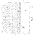
- FIG. 9 is an enlarged view of the portion of FIG. 6 that is referenced “A” in the figure, showing a transfer tunnel between stage vessels, which showing is similar for an enlarged view of the portion of FIG. 8 that is similarly labeled;
- FIG. 10 is a schematic perspective view of a portion of the multistage system of FIG. 6 showing a possible configuration of two stage vessels and their associated transfer tunnels;
- FIG. 11 is an enlarged elevation of a fluidized gas inlet nozzle, also known as a tuyere, useful in the multistage system shown in FIG. 6 ;
- FIG. 12 is an enlarged plan view of a portion of a gas distributor plate useful in the multistage system shown in FIG. 6 ;
- FIG. 13 is a graph showing possible residence time distributions for two multistage fluidized solids processing systems according to the invention having 60 stages and 85 stages respectively;
- FIG. 14 is a graph showing possible residence time distributions for fluidized solids systems having various numbers of stages.
- FIG. 1 One known method of continuous processing of fluidized particulate solids for thermal conditioning, chemical or other treatments can employ a fluidized bed processing vessel such as is shown in FIG. 1 .
- particulate solids are continuously supplied into an upper portion of a closed cylindrical processing vessel via a solids feed nozzle and are discharged from the other side of the vessel via a fixed height discharge outlet.
- the vertical position of the discharge outlet largely determines the height of the solids mass in the processing vessel under steady state conditions.
- Fluidizing gas is supplied to the bottom of the vessel through a distributor plate bearing gas nozzles, sometimes known as “tuyeres” (not shown), and outputs from the top of the processing vessel.
- the vertical flow rate of the gas is controlled to cause the particulate solids to fluidize and the resultant fluidized bed of solids generally will behave somewhat like a fluid.
- solids can be fed at a constant volumetric flow rate to the processing vessel through the feed nozzle and allowed to overflow out of the processing vessel at the same constant volumetric flow rate through the discharge outlet.
- the volume of the fluidized bed of solids in the processing vessel is maintained at a constant level, V.
- the fluidized bed of solids can be thermally treated or chemically reacted with the gas stream used to fluidize the solids, or may be subject to both thermal and chemical treatment.
- the processing vessel can be surrounded by a heating mantle, to elevate the temperature of the fluidized solids to a desired processing temperature for reaction with the flowing gas stream.
- a typical fluidized solids regimen has good heat transfer characteristics which can provide reasonably uniform temperature distribution between the gas phase and the particulate solids throughout the processing vessel. With efficient construction, the heating or cooling provided by the mantle surrounding the processing vessel can effectively maintain the fluidized solids bed within desired temperature limits for either endothermic or exothermic reactions. This desirable behavior can be attributed to factors such as a high heat transfer coefficient between the processing vessel wall and the moving bed of fluidized solids and the mixing provided by fluidization.
- the residence time of the solid particles in the system is important and desirably should be predictable and uniform for all solids particles traversing the system. What is sometimes referred to as “plug flow behavior”, wherein the fluidized solids move as a plug, can also be desirable. However, in practice, these goals are sometimes difficult to meet.
- the solid particles are moved through the processing vessel from the feed location to the discharge location by driving forces such as pressure differential, mechanical motivation or leveling of the fluidized medium.
- the solid particles are continuously in motion relative to one another, in a randomized manner.
- the fluidizing gas creates voids or “bubbles” that impart further motion to the particles.
- One effect of this constant and randomized motion of the particles is that individual particles take different paths through the processing vessel from the feed point to the discharge point and travel at different velocities according to the particular path a particle may follow. Consequently, different particles experience different residence times in the processing vessel, which can adversely affect processing consistency.
- Baffles have been employed to constrain the particles to a relatively uniform path through the processing vessel, with a view to achieving a more uniform particle residence time in the processing vessel, with limited success.
- a horizontal configuration can be desirable for fluidized gas-solids processes.
- FIGS. 2 and 3 One known embodiment of horizontal series continuous multistage fluidized bed thermal or chemical processing apparatus is shown schematically in FIGS. 2 and 3 .
- the processing apparatus comprises N stage vessels not all of which are shown.
- the first stage vessel is labeled “Stage 1 ”
- the last stage is labeled “Stage N”
- successive intermediate stage vessels are labeled “n”, “n+1”, and “n+2” respectively.
- Processing apparatus is known or has been proposed which has up to 12 stage vessels and all the stage vessels have the same volume and can be operated to have the same volume V of fluidized bed solids.
- the stage vessels can have different volumes, if desired.
- stage vessels are connected together in series by transfer tunnels, for example pipes, extending between each stage vessel and its neighbor, as is shown in more detail in FIG. 3 , both FIGS. 2 and 3 being schematic, as stated.
- Each transfer tunnel is disposed just above the level of a gas distribution plate which is usually located at the bottom of the stage vessel to supply fluidizing gas to the stage vessel. This location is useful to assist in transferring larger particles present in the fluidized solids which may gravitate to the bottom region of the fluidized bed and could become trapped behind a dividing wall.
- the solids product to be processed can be fed continuously to Stage 1 at a desired constant volumetric production rate, designated r.
- the fluidized solids in Stage 1 having volume, V, are processed for an average residence time, V/r, and flow continuously and when a steady state is attained, flow successively from stage to stage at rate r, to final Stage, N, from which the solids are continuously discharged from the system.
- the solid particle populations traveling through the system have a residence time which depends upon the shape and size of the individual stages.
- the residence time distribution of the particles which can be designated P(t r ), can be determined theoretically or by experiment.
- One example of a suitable experimental procedure is to operate the system under steady state conditions with a constant feed rate and then to introduce a quantity of particulate material into the feed stream as tracer particles.
- the introduced material particles desirably have the same physical characteristics as the particles being processed but also have a monitorable feature that distinguishes them from the other particles being processed. If this quantity of tracer particles is introduced over a known short period of time, t i , relative to the average residence time of particles being processed, T r , a time-related measurement of tracer particles leaving the system, which can be termed an “impulse response function” can be employed to provide an actual residence time distribution function P(T r ) for the total population of particles being fed.
- a small batch of dark colored particles can be mixed in with a white or light colored feedstock of the same material to act as tracers, and the distribution over time of the dark colored particles in the output can be determined as a proportion of the output, by colorimetry.
- FIG. 4 shows the percent of the particle population being discharged from the reactor, designated P(t r ), against residence time in the reactor, t r .
- the constant K normalizes the ordinate for the area under the curves to be unity so that the entire population is 1.0.
- the nature of the distribution is usually significant when processing a product whose residence time in the system has to meet designated parameters to achieve a desired quality.
- the curve starts at zero because zero particles leave the system in zero time. In the real world, it takes some time for a particle entering a stage vessel to find the discharge point. Accordingly, it requires a finite time, referenced “ ⁇ ” in FIG. 4 , for any particle in the stage vessel to get to the discharge point.
- T r the designated residence time
- the invention can provide a novel multistage processing system having a multiplicity of stage vessels and which nevertheless can yield a desirable distribution curve for the residence times of the particulate solids processed by the system. For example, only small proportions of particles may have undesirably short or undesirably long residence times in the system.
- the flow area of the passage between stages be small to help control forward and back mixing but small flow passages can lead to obstructions, resulting in a broadening of the residence time distribution function, P(Tr).
- each passageway between stages must usually remain unobstructed to avoid shutting down or slowing the process. If a passageway does become obstructed, it would be desirable to have convenient access to the tunnel or other passageway to clear the obstruction.
- the driving force that moves the fluidized solids through the system is the level increment, designated ⁇ H n in FIG. 3 , of the fluidized solids between any stage, n, and a subsequent stage, n+1. Since fluidized solids behave hydraulically like a liquid phase, in certain respects, this differential level, shown as ⁇ h n between the phases drives the flow of fluidized solids from stage, n, to stage, n+1, through the connecting transfer tunnel. In a multistage system it is important that the pressure drop through each transfer tunnel, or other connector between stages, be low, because in a series of stages the pressure drops are additive.
- an embodiment of multistage fluidized bed processing system can comprise sixty stages arranged in series with fifty nine transfer tunnels connecting the stages together.
- each stage should require the same pressure drop, ⁇ h m , to handle a specified process flow rate.
- ⁇ h m is 0.25 inches of fluidized product
- the multistage system is inclined downwardly in the direction of flow of product through the system to provide a gradient yielding a gravitational reduction in the pressure difference required to maintain flow.
- inclining the system may also be undesirable from an engineering or a processing standpoint in some cases.
- the invention also provides embodiments of multistage fluidized bed processing system employing one or more transfer tunnels between stages which can operate effectively and reliably with relatively low pressure drops through the transfer tunnels.
- Some embodiments of the invention can operate with values for ⁇ H m of one-sixteenth of an inch, i.e. 0.0625 inches, or less.
- the invention provides, in some embodiments a low-pressure drop transfer tunnel which can nevertheless effectively limit intermixing between stages.
- a further difficulty to be overcome in providing a multistage fluidized bed continuous processing system is that in many multistage processing applications, it is desirable to control the temperature of the several fluidized beds of solids. All the beds may be desired to have the same temperature or a specific temperature profile from stage to stage may be needed to meet the requirements of a particular process being performed in the system. Such temperature requirements have typically been met by providing heating or cooling around the vessel walls forming the various process stages.
- known heating or cooling means such as tube bundles or heating mantles around the vessels, may become unduly complex, cumbersome and costly for a multistage system having a relatively large number of stages.
- the invention provides a continuous multistage fluidized bed processing system and method for gas solids contacting in commercial applications such as the system embodiment illustrated in FIGS. 5-12 of the drawings.
- the system can comprise a large number of stages, such as six or more up to hundreds and can provide good uniformity of residence time on a particle-to-particle basis.
- FIG. 5 The particular system embodiment shown in FIG. 5 is a sixty stage continuous processing system wherein the sixty stages are arranged in series from a feed input point to a discharge point as shown in FIG. 7 .
- the illustrated embodiment of multistage system has a base plate 10 , which comprises a lower section 11 of the containing wall of each of a multiplicity of stage vessels 12 as well as a top wall 42 and side walls 40 for each of a number of transfer tunnels 18 .
- Transfer tunnels 18 extend between adjacent stages 12 and form passageways connecting successive stage vessels 12 for transfer of solids from one stage vessel 12 to another. Transfer tunnels 18 are sufficient in number to connect stage vessels 12 together in a desired pattern. For a single series of stage vessels 12 , the number of transfer tunnels 18 can for example be one less than the number of stage vessels 12 .
- Base plate 10 can comprise a generally flat plate from which stage vessels 12 and transfer tunnels 18 project upwardly.
- Base plate 10 can be fabricated as an integral unitary piece from a thick metal plate or casting of metal or refractory material or can have another suitably substantial construction, and can, if desired, comprise a structural backbone of the system, providing support for other system elements.
- One embodiment of base plate 10 can be manufactured as a complex comprising lower sections 11 of stage vessels 12 and transfer tunnels 18 using suitable cutting equipment, for example, water jet cutting equipment to cut suitable openings, channels or other shapes from a monolithic plate or slab of suitable material.
- base plate 10 can have a thickness in the range of from about 25 mm to about 250 mm (approximately one to ten inches thick). If desired base plate 10 can be thicker than these dimensions or can be formed in sections or components or multiple pieces which are secured together to form a structural unit and optionally can be detached from one another, if desired. Some components of base plate 10 can be permanently secured together by welding, riveting or other suitable means, if desired. Base plate 10 can have any combination of compatible ones of these features.
- base plate 10 can be flange-mounted above a plenum chamber 20 which provides pressurized fluidizing gas to stage vessels 12 .
- a fluidizing gas distributor plate 22 Sandwiched between plenum chamber 20 and base plate 10 is a fluidizing gas distributor plate 22 which distributes fluidizing gas to stage vessels 12 and transfer tunnels 18 .
- Gas distributor plate 22 extends beneath stage vessels 12 and transfer tunnels 18 and supports a multiplicity of gas inlets, which in the system embodiment shown can be gas injection nozzles 24 , or tuyeres. Fluidization gas is provided to stage vessels 12 and transfer tunnels 18 through gas nozzles 24 which communicate through gas distributor plate 22 with a pressurized gas-containing plenum or chamber 20 .
- Gas distributor plate 22 can be constructed as a common integral unitary member serving all stage vessels 12 , and optionally can be monolithic, if desired. Alternatively, gas distributor plate can be formed of a number of separate or separable components, which optionally may be assembled into an integral unitary member for use. Gas distributor plate 22 can be formed from a continuous sheet of steel, aluminum alloy or other suitable material, or can be formed from two or more sheets joined together.
- gas distributor plate 22 is removably attachable to base plate 10 .
- plenum housing 31 can carry peripheral flanges 25 which bolt through gas distributor plate 22 to attach plenum housing and gas distributor plate 22 to base plate 10 , sandwiching gas distributor plate 22 between plenum housing 31 and base plate 10 .
- Gas distributor plate 22 can then be separated from base plate 10 , by opening the bolted flanges and lowering gas distributor plate 22 and plenum chamber 20 to provide good access to transfer tunnels 18 .
- gas distributor plate 22 and plenum chamber 20 are slidable as a unit, or separately, relatively to base plate 10 , in a horizontal direction, for example on tracks attached to base plate 10 .
- Gas distributor plate 22 and plenum chamber 20 can be slidable in one direction to provide access to some transfer tunnels 18 and stage vessels 12 and slidable in the opposite direction to provide access to the other transfer tunnels 18 and stage vessels 12 .
- the ability to remove or open gas distributor plate 22 and plenum chamber 20 provides convenient access to transfer tunnels 18 and the interiors of stage vessels 12 to clear obstructions, for routine cleaning and maintenance and for other purposes.
- gas nozzles 24 are arranged in a pattern which matches the pattern of lower sections 11 of the multiplicity of stage vessels and the interiors of transfer tunnels 18 and which serves to feed the fluidizing gas into stage vessels 12 and transfer tunnel 18 .
- the pattern of gas nozzles 24 and any other variable characteristics relating to gas nozzles 24 can be selected to maintain the fluidized solids in a fluidized state, desirably with good uniformity of fluidization, as fluidized solids pass through the multistage system from one vessel stage 12 to another vessel stage 12 and through transfer tunnels 18 .
- the pattern of gas nozzles 24 in gas distributor plate 22 is such that none are present outside the areas of stage vessels 12 and transfer tunnels 18 . In one embodiment of the invention, no gas nozzles 24 are present in the areas between individual stage vessels 12 or in the vicinity of their surrounding walls (to be described).
- each gas nozzle 24 here shown comprises a tuyere having a neck 26 and a durable, optionally solid, head 28 .
- Neck 26 is traversed by a vertical feeder passage 27 and head 28 is traversed by one or more downwardly inclined radial distributor passages 30 communicating with feeder passage 27 .
- Gas passages 30 connect with hollow neck 26 and open out on the underside of gas nozzle head 28 .
- gas passages 30 can be from two to six in number and can be evenly distributed around gas nozzle head 28 .
- Each gas nozzle 24 extends through distributor plate 22 and opens into plenum chamber 20 to receive fluidizing gas from plenum chamber 20 .
- Gas nozzle 24 discharges the received gas onto the floor of the respective stage vessel 12 or transfer tunnel 18 in which it is located, optionally in a number of directions according to the number and disposition of gas passages 30 .
- Heads 28 of gas nozzles 24 desirably are of sturdy and durable construction as to sustain constant abrasion by the moving fluidized solids particles, without unacceptable damage or wear.
- fluidized gas inlets can be employed in place of gas nozzles 24 , if desired, as is known to or becomes known to a person of ordinary skill in the art.
- the fluidized gas inlets can comprise simple openings or perforations in a gas distributor plate 22 .
- some means can be provided to block or obstruct the openings, or perforations, to prevent solids falling through them if there is no gas flow, for example a bolt could be loosely fitted into each hole or perforation.
- gas nozzles 24 are spaced on an orthogonal grid relatively closely to each other, for example with a space between the heads 28 of adjacent gas nozzles that is no greater than about the width of a head 28 .
- FIG. 12 One possible arrangement of gas nozzles 24 is shown in FIG. 12 .
- each stage vessel 12 has a rectangular grid of 3 ⁇ 7 gas nozzles 24 , that an additional smaller gas nozzle 24 is provided at each end of the grid in the curved portion of the stage vessel section and a further small gas nozzle 24 is provided in each transfer tunnel 18 .
- Each transfer tunnel 12 or some transfer tunnels 12 , can be provided with two or more gas nozzles 24 or other fluidizing gas inlets, if desired, supported by that portion of gas distributor plate 22 which provides the floor of the respective transfer tunnel 18 .
- gas distributor plate 22 can provide a bottom wall or floor for stage vessels 12 and also for transfer tunnels 18 , with gas nozzles 24 project upwardly into the respective stage vessels 12 and transfer tunnels 18 . It can be understood that in the illustrated embodiment of system according to the invention, gas distributor plate 22 extends beyond any individual stage vessel 12 , across the vessel walls, beneath the space between neighboring stage vessels 12 , beneath any transfer tunnels connecting with the individual stage vessel and beneath one or more neighboring stage vessels. However, other constructions of gas distributor plate 22 can be employed, if desired.
- Plenum chamber 20 comprises a pressurized gas chamber enclosed by a plenum housing 31 and supplied with gas from a gas supply pipe 32 .
- Plenum chamber 20 extends beneath substantially the whole area of distributor plate 22 to be freely accessible to feeder passage 27 of each gas nozzle 24 .
- a priming zone 34 can be divided off plenum chamber 20 by a dividing wall 36 , to maintain gas pressure in the first vessel stages of the system during startup before downstream stage vessels 12 fill with solids.
- priming zone 34 can have its own gas supply pipe 38 .
- plenum chamber 20 is sectionalized, each section serving a number of gas nozzles 24 supplying one or more stage vessels 12 or transfer tunnels 18 .
- plenum chamber 20 has sufficient capacity to buffer fluctuations in gas supply and demand and provide a constant pressure gas source for gas nozzles 24 .
- each stage vessel lower section 11 is defined by a vertical oval-shaped opening which extends through base plate 10 from one side to the other.
- Transfer tunnel sides 40 and roof 42 are defined by a rectangular-sectioned channel in lower section 11 which opens downwardly.
- stage vessel lower sections 11 and transfer tunnels 18 are closed by gas distributor plate 22 .
- Gas nozzles 24 supported by gas distributor plate 22 are accommodated in the respective cutaway portions of base plate 10 .
- Transfer tunnels 18 are desirably little, if any, longer than is necessary for effective control of back mixing and forward mixing, and desirably also are sufficiently long to fully accommodate at least one gas nozzle 24 .
- Transfer tunnels 18 can have any suitable height. Desirably each transfer tunnel 18 has a sufficient height for the particulate solids being processed to flow over the gas nozzle or nozzles 24 located in a respective transfer tunnel 18 . It can also be useful for the height and/or other dimensions, of one or more of transfer tunnels 18 , or of all transfer tunnels 18 , to be such that fluidizing gas admitted through the gas nozzle or inlets 24 located in the respective transfer tunnel 18 impacts the roof 42 of the transfer tunnel and is deflected laterally to facilitate flow of solids through the transfer tunnel 18 . In a given embodiment of multistage system, all the transfer tunnels 18 can have similar dimensions, if desired.
- transfer tunnels 12 can be varied within a given multistage system embodiment.
- some downstream transfer tunnels 12 are fabricated with smaller cross-sectional areas to maintain a constant flow velocity of the fluidized solids through the multistage system.
- Removable tunnel inserts or the like can be inserted in selected transfer tunnels 12 , to reduce the tunnel cross-sections for some processes, and can be removed for others, if desired.
- Each stage vessel 12 further comprises a tubular upper section 44 which mates with and, if desired, can be welded at its base, or otherwise affixed, to a respective lower section 11 of base plate 10 , to complete the multistage array of stage vessels 12 .
- Upper sections 44 and lower sections 11 together define the size and shape of each stage vessel shown.
- stage vessels 12 all have the same size and shape.
- stage vessels 12 could have different sizes or different shapes or both different sizes and different shapes, if desired.
- each stage vessel 12 has a uniform cross-section throughout its height taking the form of an elongated oval with smoothly rounded ends. This elongated shape with ends that are internally smoothly contoured in the direction of fluidized solids flow is believed helpful to efficient operation of the multistage system.
- the exemplary embodiment of multistage system illustrated in the drawings comprises an array of three parallel horizontal rows of stage vessels 12 , each row containing twenty stage vessels.
- the sixty stage vessels 12 are connected together by transfer tunnels 18 to provide a sinuous path for fluidized solids to flow through each stage vessel 12 in series from a solids feed port 46 to a solids discharge port 48 .
- stage vessels 12 are sequentially numbered from 1 to 60 according to the sequence of flow in which they are connected.
- transfer tunnels 18 can be connected in end alignment or laterally with stage vessels 12 .
- a transfer tunnel 18 can be connected in endwise alignment with one stage vessel 12 and laterally to the next stage vessel 12 .
- Other arrangements and numbers of stage vessels will be or become apparent to a person of ordinary skill in the art in light of this example and this disclosure.
- the flow path could have a Y configuration with two smaller flow paths merging into a single larger flow path.
- containing wall 50 which encloses and houses upper sections 44 of stage vessels 12 .
- containing wall 50 can bear flanges 52 and 54 around its top and bottom peripheries respectively, or can be provided with other suitable attachment means.
- Bottom flange 54 can be connected to base plate 10 by bolts or the like.
- the height of containment wall 50 usefully can be chosen to be equal to the height of upper sections 44 of stage vessels 12 so that a seal plate 56 located on top of containing wall 50 can seal against stage vessels 12 as well as containment wall 50 , employing one or more gaskets, if desired.
- Seal plate 56 defines with containing wall 50 , upper sections 44 of stage vessels 12 and base plate 10 , a temperature control fluid enclosure 58 common to all or a desired number of stage vessels 12 .
- Temperature control fluid enclosure 58 can be employed to circulate heating or cooling gas or liquid around stage vessels 12 , to control the temperature of stage vessels 12 .
- Temperature control fluid for example air
- Temperature control fluid enclosure 58 can be divided into multiple sub-regions controllable to have different temperatures, one sub-region from another sub-region, if desired.
- the multistage continuous processing fluidized bed system shown comprises a freeboard chamber 60 mounted on top of heating chamber seal plate 56 by means of a peripheral flange 64 which can be bolted or otherwise secured to top flange 52 of containment vessel 50 .
- a peripheral flange 64 which can be bolted or otherwise secured to top flange 52 of containment vessel 50 .
- Other means of securing freeboard chamber 60 to the system can be employed, if desired.
- Freeboard chamber 60 provides a top closure can collect the off gas generated by each stage vessel 12 and discharge it through one or more gas discharge ports 62 .
- One embodiment of the invention comprises a continuous multistage fluidized bed processing system having as many stages as are necessary to achieve a desired degree of uniformity of residence time of the particles being processed.
- pressurized air is supplied to plenum chamber 20 and priming zone 34 to establish a fluidizing air flow through gas nozzles 24 .
- heating or cooling gas is admitted to temperature control gas enclosure 58 , and time is allowed for temperature conditioning of the system, if necessary.
- a particulate solids feedstock for example aluminum oxide grit powder, is then fed into the system through solids feed port 46 and into the first stage vessel 12 , at a predetermined constant volumetric rate related to the characteristics of the system and of the feedstock.
- the particulate solids drops towards the floor of the first stage vessel 12 where it encounters upward air flow from gas nozzles 24 in the portion of gas distributor plate 22 constituting the floor of the stage vessel. This upward air flow fluidizes the descending particulate solids. As more particulate solids flow into the first stage vessel 12 , the downward pressure applied by the upwardly building bed of fluidized solids moves the solids into the first transfer tunnel 12 . In the first transfer tunnel 18 , the fluid solids encounter air flow from the gas nozzle or nozzles 24 in transfer tunnel 18 which maintains fluidization and prevents plugging of the tunnel.
- the hydrostatic-like pressure of the bed of fluidized solids in the first stage vessel 12 moves the fluidized solids into the first transfer tunnel 18 directing the air flow from the gas nozzle or nozzles 24 in the transfer tunnel 18 toward the next stage vessel 12 , thereby facilitating movement of the fluidized particulate solids through transfer tunnel 18 into the next stage vessel 12 .
- the gas nozzle or nozzles 24 in the transfer tunnel 18 also maintain fluidization of the particulate solids during their transit through transfer tunnel 18 .
- Particulate solids entering the second stage vessel 12 promptly encounter the upward flow of fluidizing air emerging from gas nozzles 24 in the second stage vessel 12 which maintains fluidization of the particulate solids emerging into the second stage vessel 12 .
- Continued flow of particulate solids through the first transfer tunnel 18 builds up a bed of fluidized solids in the second stage vessel 12 providing a hydrostatic-like pressure head to move the flow of particulate solids into and through the second transfer tunnel 18 into the third stage vessel 12 .
- the process repeats through all the stage vessels 12 in the multistage system until the last stage vessel 12 is reached and the flow of particulate solids reaches the last stage vessel 12 and emerges from solids discharge port 48 .
- a steady state such as is shown in FIG. 6 can be reached where the height of the bed of fluidized solids 66 in each stage vessel 12 shows a diminishing progression along the sequence of stage vessels 12 traversed by the flow of particulate solids.
- the differential in height between one stage vessel 12 and the next is indicative of the pressure required to move the particulate solids flow through the connecting transfer tunnel 18 .
- the fluidizing action of gas nozzle or nozzles 24 in each transfer tunnel 18 is effective to prevent obstructions in the tunnels which could disrupt orderly flow of the particulate solids through the system.
- the process can be stopped, and the obstruction can be cleared by unbolting flanges 25 and lowering plenum housing 31 and gas distributor plate 22 away from base plate 10 , providing good access to transfer tunnels 18 to clear the obstruction or obstructions. Access is at the same time provided to the interiors of stage vessels 12 , should that be needed for routine or emergency maintenance or other purposes.
- Efficient tunnel design can be helpful in making systems with large numbers of stage vessels feasible. For example with a sixty-stage system, there are fifty-nine tunnels that must work reliably. Any single tunnel malfunctioning can shut down the processing line, which may be very costly to a high volume processing facility.
- each stage vessel 12 has a cross-sectional size of about 102 mm by about 305 mm (about 4 inches by 12 inches) and a height of about 1143 mm (about 45 inches).
- the fifty-nine transfer tunnels 18 that connect the stage vessels together each have a rectangular cross-sectional shape of about 38 mm (about 1.5 inches) wide and about 44 mm (about 1.75 inches) high and have a length of about 25 mm (about 1.0 inch).
- Each transfer tunnel 18 contains two fluidized gas nozzles 24 to provide good fluidization in the tunnels and yield a low pressure drop at designed production flow rates.
- heated air Prior to feeding product into the multistage system, heated air is admitted into temperature control gas enclosure 58 and the system is allowed to establish a temperature of 250° C. throughout the stage vessels 12 .
- the white particulate aluminum oxide product is then fed into the first stage of the 60-stage system at a volumetric flow rate controlled to be 3780 lbs/hr.
- the system has a fluidized bed level of about 744 mm (about 29.3 inches) at the feed point in stage vessel number 1 one and a level of about 521 mm (about 20.5 inches) at the discharge point in stage vessel number 60 .
- the difference in bed height between the first and the last stage vessels, namely about 224 mm (about 8.8 inches) of fluidized solids, can be understood as indicating the total pressure drop occurring across the 59 transfer tunnels 18 which connect the sixty stage vessels 12 .
- Dividing the pressure drop by the number of transfer tunnels yields a figure of about 3.8 mm (about 0.15) inches of fluidized bed equivalent pressure drop per transfer tunnel. This is a surprisingly low figure attributable to features of the invention, for example the injection of fluidized gas into the transfer tunnels 18 and, possibly, also to the cross-sectional shape of the stage vessels 12 . Without transfer tunnel gas inlets 24 , transfer tunnels 18 having a smooth floor throughout their length in place of transfer tunnel gas inlets 24 , the pressure drop is contemplated as being substantially higher.
- the described dimensions provide a freeboard height between the top of the fluidized bed level and the top of the stage vessel 12 of about 406 mm (about 16 inches) in stage vessel number 1 increasing to about 622 mm (24.5 inches) in stage vessel number 60 .
- the average fluidized bed volume in each stage is about 1,980 cubic centimeters (about 0.70 cubic feet).
- the average residence time of the total aluminum oxide particle population flowing through the unit is one hour.
- the bulk density of the fluidized aluminum oxide at an air fluidization rate of about 3.35 meters (about 11.0 feet) per minute in the multistage system described is about 1442 kilograms per cubic meter (about 90 lbs per cubic foot).
- FIG. 13 Some results obtainable by this method are shown in FIG. 13 where, as in FIG. 4 , the actual residence time is plotted on the abscissa as a proportion of the average residence time and the ordinate is normalized for the area under the curves to be unity so that the residence time of the entire population is 1.0.
- the abscissa of the graph shown in FIG. 13 is the fraction of the one hour average residence time experienced by the particle population.
- the ordinate of this graph is a scale factor giving the area under the curve equal to unity, i.e. the entire population.
- the area under the curve between two values of residence time is the fraction of the total population having a residence time between the two values.
- the two graphs shown in FIG. 13 represent the output from a mathematical model idealized for a 60 stage system and an 85 stage system, respectively.
- analysis of the fraction of brown particles output in the test described above can yield data points which all lie between these two graphs, suggesting that the actual 60 stage unit has an efficiency slightly higher than would be expected from theoretical considerations. While the invention is not limited by any particular theory, this useful finding may be attributable to the particular oval geometric shape of the individual stage vessels 12 and to the use of gas nozzles 24 to inject fluidizing gas into transfer tunnels 18 .
- residence time uniformity can be enhanced by employing a multistage system having a larger number of stages, as can be understood from FIG. 14 .
- FIG. 14 shows modeled-determined residence time graphs for the cases where the number of stage vessels N is equal to 10, 20, 60, and 120 stages. It can be seen from the figure that in the 120 stage case, more than 80 percent of the total particle population (81.6 percent) is between plus and minus 20 percent of the average residence time. Comparable graphs can be generated by a person of ordinary skill in the art for other numbers of stages, enabling multistage system embodiment of the invention having a suitable number of stages to be selected for a particular industrial, commercial or research application.
- the multistage system can have at least about 15 stage vessels; from about 40 stage vessels to about 500 stage vessels; from about 100 stage vessels to about 200 stage vessels; from about 50 stage vessels to about 70 stage vessels; or from about 80 stage vessels to about 200 stage vessels and the methods of the invention can be performed in systems having such numbers of vessels.
- Fabricating the lower sections of stage vessels 12 and transfer tunnels 18 from a robust, integral base plate, such as base plate 10 can be economical and can facilitate accurate positioning of the individuals stages of the multistage system with respect to one another and of the transfer tunnels with respect to stage vessels 12 .
- Fabrication of base plate 10 as an integral or monolithic unit helps assure that proper spatial relationships of stage vessels 12 and transfer tunnels 18 are maintained during the useful life of the processing system. These measures can all contribute to the effectiveness of high volume and other embodiments of multistage system according to the invention.
- gas distributor plate 22 with a suitable pattern of fluidization injection nozzles 24 , termed “tuyere”, servicing the stage vessels as well as the transfer tunnels, can afford good solids fluidization characteristics facilitating consistent passage of the particulate solids through the system.
- the fluidizing gas in a transfer tunnel 18 can strike the roof of the transfer tunnel and turn in the direction of flow of product through the tunnel promoting reliable operation of the transfer tunnel and reducing possible plugging or other obstruction of the tunnel with the solid particles.
- one or more gas nozzles 24 can project into the solid flow path through the tunnels, without causing tunnel blocking or obstruction, as this can be prevented by the flow of fluidization gas from the one or more gas nozzles 24 in the transfer tunnel 18 .
- base plate 10 can employ geometry which sufficiently separates stage vessels 12 from each other as to permit circulation of a heating or cooling medium around the stage vessels, providing good heat transfer conditions to stage vessels 12 and facilitating control of processing temperatures in the stage vessels, enabling a desired temperature profile to be maintained from a first to a last stage vessel 12 .
- Some embodiments of the invention provide technically and economically feasible multistage methods for processing particulate solids which can be utilized with a large number of stages, for example 20, 60, 120, or hundreds of stages, for processes employing interactions between the particulate solids and a gas phase.
- Such inventive embodiments can, in some cases, provide good uniformity of residence time of the population of particles in the multistage reactor and a high quality output.
- the invention can provide other benefits.
- useful embodiments of the processes and systems of the invention can transfer fluidized solids reliably from one stage vessel to the next, with a low pressure drop during the transfer.
- Further embodiments of the invention can provide convenient access to a multiplicity of transfer tunnels connecting stage vessels together into a continuous processing system, to permit prompt cleaning or maintenance, or both, in the event of that one or more transfer tunnels should fail to operate effectively.
- the invention provides embodiments wherein the stage vessels can be mounted in a system enclosure to permit convenient and controlled heating or cooling of the stage vessels by gas circulating in a common region or zone. Still further, embodiments of the invention provide a method and mechanism to gain convenient access to each of a large number of stages in a multistage fluidized solids continuous processing system for cleaning, washing, draining and maintaining the stage vessels and transfer tunnels, distributor plate, and plenum chamber, if employed.
- Embodiments of multistage system according to the invention can be employed for processing a wide variety of solids materials in particulate form that can be fluidized with a gas.
- multistage system embodiments can be employed for continuous drying, or heating, or both heating and drying of processing of sensitive materials requiring a time-temperature processing history having good uniformity of residence time.
- Some products which conventionally have required repeated batch processing to meet a quality standard can be processed on a continuous basis, employing a multistage fluidized bed system embodiment of the invention.
- Some useful embodiments of the invention can provide low heat losses and good energy efficiency, high product throughput, and good uniformity of residence time.
- the novel transfer tunnel design described herein can be employed to reduce or eliminate particle by-passing and holdback which can adversely affect residence time uniformity.
- the invention includes multistage system fluidized bed processing embodiments comprising from ten to two hundred vessel stages, or other desired numbers of stages, in cost-effective mechanical designs which by employment of a removable gas distributor plate, or other comparable measures, can provide good access for cleaning the system for product changeovers or for routine maintenance.
- stage vessels 12 can have bottoms inclined in the direction of particulate solids flow, or one vessel can be vertically displaced with respect to another, to promote gravitational flow through the system.
- processes are described as having, including, or comprising specific process steps, it is contemplated that processes according to the present invention can also consist essentially of, or consist of, the recited processing steps. It should be understood that the order of steps or order for performing certain actions is immaterial so long as the invention remains operable. Moreover, two or more steps or actions may be conducted simultaneously.
Landscapes
- Chemical & Material Sciences (AREA)
- Organic Chemistry (AREA)
- Chemical Kinetics & Catalysis (AREA)
- Engineering & Computer Science (AREA)
- Combustion & Propulsion (AREA)
- Life Sciences & Earth Sciences (AREA)
- Microbiology (AREA)
- Mechanical Engineering (AREA)
- General Engineering & Computer Science (AREA)
- Devices And Processes Conducted In The Presence Of Fluids And Solid Particles (AREA)
Abstract
Description
Claims (16)
Priority Applications (9)
| Application Number | Priority Date | Filing Date | Title |
|---|---|---|---|
| US11/941,644 US7829031B2 (en) | 2007-11-16 | 2007-11-16 | Methods and systems for multistage processing of fluidized particulate solids |
| EP08019860.9A EP2060320B1 (en) | 2007-11-16 | 2008-11-13 | System for multistage processing of fluidized particulate solids |
| MX2008014611A MX2008014611A (en) | 2007-11-16 | 2008-11-14 | Methods and systems for multistage processing of fluidized particulate solids. |
| JP2008292083A JP2009148747A (en) | 2007-11-16 | 2008-11-14 | Method and system for multi-stage treatment of fluidized particle-shaped solid |
| CA 2643871 CA2643871C (en) | 2007-11-16 | 2008-11-14 | Methods and systems for multistage processing of fluidized particulate solids |
| AU2008246216A AU2008246216B2 (en) | 2007-11-16 | 2008-11-14 | Methods and systems for multistage processing of fluidized particulate solids |
| RU2008145032/02A RU2484889C2 (en) | 2007-11-16 | 2008-11-14 | Methods and systems for multistage processing of liquefied solid particles |
| CN201610630828.4A CN106179137B (en) | 2007-11-16 | 2008-11-17 | Method and system for multistage treatment of fluidized particulate solids |
| CNA2008101782759A CN101455952A (en) | 2007-11-16 | 2008-11-17 | Methods and systems for multistage processing of fluidized particulate solids |
Applications Claiming Priority (1)
| Application Number | Priority Date | Filing Date | Title |
|---|---|---|---|
| US11/941,644 US7829031B2 (en) | 2007-11-16 | 2007-11-16 | Methods and systems for multistage processing of fluidized particulate solids |
Publications (2)
| Publication Number | Publication Date |
|---|---|
| US20090130004A1 US20090130004A1 (en) | 2009-05-21 |
| US7829031B2 true US7829031B2 (en) | 2010-11-09 |
Family
ID=40293859
Family Applications (1)
| Application Number | Title | Priority Date | Filing Date |
|---|---|---|---|
| US11/941,644 Active 2028-11-11 US7829031B2 (en) | 2007-11-16 | 2007-11-16 | Methods and systems for multistage processing of fluidized particulate solids |
Country Status (8)
| Country | Link |
|---|---|
| US (1) | US7829031B2 (en) |
| EP (1) | EP2060320B1 (en) |
| JP (1) | JP2009148747A (en) |
| CN (2) | CN101455952A (en) |
| AU (1) | AU2008246216B2 (en) |
| CA (1) | CA2643871C (en) |
| MX (1) | MX2008014611A (en) |
| RU (1) | RU2484889C2 (en) |
Cited By (2)
| Publication number | Priority date | Publication date | Assignee | Title |
|---|---|---|---|---|
| US20100322836A1 (en) * | 2009-06-23 | 2010-12-23 | Chevron Phillips Chemical Company Lp | Continuous preparation of calcined chemically-treated solid oxides |
| US9827547B2 (en) | 2013-08-15 | 2017-11-28 | Hatch Ltd. | Multi-compartment reactor and method for controlling retention time in a multi-compartment reactor |
Families Citing this family (8)
| Publication number | Priority date | Publication date | Assignee | Title |
|---|---|---|---|---|
| US7722722B2 (en) * | 2007-11-16 | 2010-05-25 | Brunob Ii B.V. | Continuous fluid bed reactor |
| RU2520802C1 (en) * | 2013-04-18 | 2014-06-27 | Федеральное автономное учреждение "25 Государственный научно-исследовательский институт химмотологии Министерства обороны Российской Федерации" | Method for control of liquid transmission through pipeline |
| JP2015134354A (en) * | 2015-03-09 | 2015-07-27 | 株式会社Ihi | Method and device for evaluating residence time of raw material grain in fluidized bed |
| DE102016218085A1 (en) * | 2016-09-21 | 2018-03-22 | Robert Bosch Gmbh | Fluidized bed system |
| CN108759430A (en) * | 2018-06-27 | 2018-11-06 | 孙院军 | A kind of bottom drying device and the drying means using the device |
| WO2023049675A1 (en) | 2021-09-23 | 2023-03-30 | Cargill, Incorporated | Thermally inhibited, ozone treated starch or flour, and a method of manufacturing a thermally inhibited, ozone treated starch or flour |
| CN114353499B (en) * | 2022-02-10 | 2023-01-24 | 安徽海蓝生物科技有限公司 | Fluidized bed for biological preparation of L-tartaric acid and preparation process thereof |
| CN114632472B (en) * | 2022-03-17 | 2023-04-21 | 株洲火炬安泰新材料有限公司 | Special forming equipment based on high-purity indium product production |
Citations (22)
| Publication number | Priority date | Publication date | Assignee | Title |
|---|---|---|---|---|
| US2892772A (en) | 1953-12-29 | 1959-06-30 | Gulf Research Development Co | Transfer of fluidized solids |
| GB891648A (en) | 1959-11-12 | 1962-03-14 | United States Steel Corp | Apparatus for transferring fluidized solids |
| US3391913A (en) * | 1966-02-23 | 1968-07-09 | Norton Co | Fluid bed kiln |
| US3745668A (en) * | 1966-03-01 | 1973-07-17 | Auxiliar Ind Sa Empresa | Apparatus for interacting particulate material with gas |
| US4068389A (en) | 1976-04-15 | 1978-01-17 | Procedyne Corporation | Gas-diffusion plate for fluidized bed apparatus |
| US4517162A (en) * | 1982-06-03 | 1985-05-14 | Exxon Research And Engineering Co. | Apparatus for use in processing a substance in a fluidized bed |
| WO1986002912A1 (en) | 1984-11-14 | 1986-05-22 | University Of Queensland | A particulate solid feeding device |
| US4828486A (en) * | 1980-04-04 | 1989-05-09 | Babcock Hitachi Kabushiki Kaisha | Fluidized bed combustor and a method of operating same |
| US5169913A (en) | 1991-05-31 | 1992-12-08 | Procedyne Corp. | Fluidized multistaged reaction system for polymerization |
| US5198029A (en) * | 1989-08-01 | 1993-03-30 | Gte Products Corporation | Apparatus for coating small solids |
| US5218932A (en) * | 1992-03-02 | 1993-06-15 | Foster Wheeler Energy Corporation | Fluidized bed reactor utilizing a baffle system and method of operating same |
| US5264196A (en) | 1984-10-15 | 1993-11-23 | Mitsubishi Materials Corporation | Multichamber type fluid bed reaction apparatus and method |
| US5423370A (en) | 1994-03-04 | 1995-06-13 | Procedyne Corp. | Foundry sand core removal and recycle |
| US5568834A (en) * | 1995-02-01 | 1996-10-29 | Donlee Technologies, Inc. | High temperature heat exchanger |
| US5796018A (en) | 1997-01-29 | 1998-08-18 | Procedyne Corp. | Process for coating iron particles with phosphorus and forming compacted articles |
| US6122842A (en) * | 1997-08-04 | 2000-09-26 | Mitsubishi Heavy Industries, Ltd. | Particle movement amount controller for fluidized beds |
| EP1072855A1 (en) | 1998-02-20 | 2001-01-31 | Kawasaki Jukogyo Kabushiki Kaisha | Multichamber division type fluidized bed furnace |
| US6253830B1 (en) | 1996-09-30 | 2001-07-03 | Procedyne Corp. | Apparatus and method for sand core debonding and heat treating metal castings |
| US6506048B1 (en) | 2001-11-01 | 2003-01-14 | Procedyne Corp. | Apparatus and method for transferring heat treated parts |
| WO2004097055A2 (en) | 2003-05-02 | 2004-11-11 | Outokumpu Technology Oy | Fluidized bed for treating iron oxide |
| US20040229182A1 (en) | 2001-09-11 | 2004-11-18 | Buhler, Ag | Continuous thermal treatment of bulk material |
| US6991767B1 (en) | 2000-09-18 | 2006-01-31 | Procedyne Corp. | Fluidized bed gas distributor system for elevated temperature operation |
Family Cites Families (7)
| Publication number | Priority date | Publication date | Assignee | Title |
|---|---|---|---|---|
| JPS5886247U (en) * | 1981-12-08 | 1983-06-11 | 川崎重工業株式会社 | fluidized bed |
| JPH0749103B2 (en) * | 1984-11-28 | 1995-05-31 | 三菱マテリアル株式会社 | Multi-chamber fluidized bed reactor |
| JPS62117626A (en) * | 1985-11-19 | 1987-05-29 | Mitsubishi Metal Corp | Multichamber type fluidized bed reactor |
| RU2089805C1 (en) * | 1994-12-19 | 1997-09-10 | Акционерное общество открытого типа "Всероссийский алюминиево-магниевый институт" | Multi-chamber apparatus |
| JPH101677A (en) * | 1996-06-17 | 1998-01-06 | Mitsubishi Heavy Ind Ltd | Fluid bed type dry distillation furnace |
| JP2862863B2 (en) * | 1997-03-31 | 1999-03-03 | 川崎重工業株式会社 | Multi-chamber split type fluidized bed furnace |
| RU2299539C1 (en) * | 2005-10-11 | 2007-05-27 | ФГОУ ВПО Уральская государственная Сельскохозяйственная академия | Method for growing of plants in greenhouses |
-
2007
- 2007-11-16 US US11/941,644 patent/US7829031B2/en active Active
-
2008
- 2008-11-13 EP EP08019860.9A patent/EP2060320B1/en active Active
- 2008-11-14 RU RU2008145032/02A patent/RU2484889C2/en active
- 2008-11-14 MX MX2008014611A patent/MX2008014611A/en active IP Right Grant
- 2008-11-14 AU AU2008246216A patent/AU2008246216B2/en active Active
- 2008-11-14 JP JP2008292083A patent/JP2009148747A/en active Pending
- 2008-11-14 CA CA 2643871 patent/CA2643871C/en active Active
- 2008-11-17 CN CNA2008101782759A patent/CN101455952A/en active Pending
- 2008-11-17 CN CN201610630828.4A patent/CN106179137B/en active Active
Patent Citations (23)
| Publication number | Priority date | Publication date | Assignee | Title |
|---|---|---|---|---|
| US2892772A (en) | 1953-12-29 | 1959-06-30 | Gulf Research Development Co | Transfer of fluidized solids |
| GB891648A (en) | 1959-11-12 | 1962-03-14 | United States Steel Corp | Apparatus for transferring fluidized solids |
| US3391913A (en) * | 1966-02-23 | 1968-07-09 | Norton Co | Fluid bed kiln |
| US3745668A (en) * | 1966-03-01 | 1973-07-17 | Auxiliar Ind Sa Empresa | Apparatus for interacting particulate material with gas |
| US4068389A (en) | 1976-04-15 | 1978-01-17 | Procedyne Corporation | Gas-diffusion plate for fluidized bed apparatus |
| US4828486A (en) * | 1980-04-04 | 1989-05-09 | Babcock Hitachi Kabushiki Kaisha | Fluidized bed combustor and a method of operating same |
| US4517162A (en) * | 1982-06-03 | 1985-05-14 | Exxon Research And Engineering Co. | Apparatus for use in processing a substance in a fluidized bed |
| US5264196A (en) | 1984-10-15 | 1993-11-23 | Mitsubishi Materials Corporation | Multichamber type fluid bed reaction apparatus and method |
| WO1986002912A1 (en) | 1984-11-14 | 1986-05-22 | University Of Queensland | A particulate solid feeding device |
| US5198029A (en) * | 1989-08-01 | 1993-03-30 | Gte Products Corporation | Apparatus for coating small solids |
| US5378434A (en) | 1991-05-31 | 1995-01-03 | Procedyne Corp. | Fluidized multistaged reaction system for polymerization |
| US5169913A (en) | 1991-05-31 | 1992-12-08 | Procedyne Corp. | Fluidized multistaged reaction system for polymerization |
| US5218932A (en) * | 1992-03-02 | 1993-06-15 | Foster Wheeler Energy Corporation | Fluidized bed reactor utilizing a baffle system and method of operating same |
| US5423370A (en) | 1994-03-04 | 1995-06-13 | Procedyne Corp. | Foundry sand core removal and recycle |
| US5568834A (en) * | 1995-02-01 | 1996-10-29 | Donlee Technologies, Inc. | High temperature heat exchanger |
| US6253830B1 (en) | 1996-09-30 | 2001-07-03 | Procedyne Corp. | Apparatus and method for sand core debonding and heat treating metal castings |
| US5796018A (en) | 1997-01-29 | 1998-08-18 | Procedyne Corp. | Process for coating iron particles with phosphorus and forming compacted articles |
| US6122842A (en) * | 1997-08-04 | 2000-09-26 | Mitsubishi Heavy Industries, Ltd. | Particle movement amount controller for fluidized beds |
| EP1072855A1 (en) | 1998-02-20 | 2001-01-31 | Kawasaki Jukogyo Kabushiki Kaisha | Multichamber division type fluidized bed furnace |
| US6991767B1 (en) | 2000-09-18 | 2006-01-31 | Procedyne Corp. | Fluidized bed gas distributor system for elevated temperature operation |
| US20040229182A1 (en) | 2001-09-11 | 2004-11-18 | Buhler, Ag | Continuous thermal treatment of bulk material |
| US6506048B1 (en) | 2001-11-01 | 2003-01-14 | Procedyne Corp. | Apparatus and method for transferring heat treated parts |
| WO2004097055A2 (en) | 2003-05-02 | 2004-11-11 | Outokumpu Technology Oy | Fluidized bed for treating iron oxide |
Cited By (5)
| Publication number | Priority date | Publication date | Assignee | Title |
|---|---|---|---|---|
| US20100322836A1 (en) * | 2009-06-23 | 2010-12-23 | Chevron Phillips Chemical Company Lp | Continuous preparation of calcined chemically-treated solid oxides |
| US9289739B2 (en) * | 2009-06-23 | 2016-03-22 | Chevron Philips Chemical Company Lp | Continuous preparation of calcined chemically-treated solid oxides |
| US9764297B2 (en) | 2009-06-23 | 2017-09-19 | Chevron Phillips Chemical Company Lp | Continuous preparation of calcined chemically-treated solid oxides |
| US10040044B2 (en) | 2009-06-23 | 2018-08-07 | Chevron Phillips Chemical Company Lp | Continuous preparation of calcined chemically-treated solid oxides |
| US9827547B2 (en) | 2013-08-15 | 2017-11-28 | Hatch Ltd. | Multi-compartment reactor and method for controlling retention time in a multi-compartment reactor |
Also Published As
| Publication number | Publication date |
|---|---|
| RU2484889C2 (en) | 2013-06-20 |
| AU2008246216B2 (en) | 2012-05-10 |
| CA2643871A1 (en) | 2009-05-16 |
| US20090130004A1 (en) | 2009-05-21 |
| CN106179137A (en) | 2016-12-07 |
| RU2008145032A (en) | 2010-05-20 |
| EP2060320A1 (en) | 2009-05-20 |
| CN106179137B (en) | 2021-05-18 |
| CA2643871C (en) | 2015-01-20 |
| AU2008246216A1 (en) | 2009-06-04 |
| MX2008014611A (en) | 2009-05-19 |
| EP2060320B1 (en) | 2018-06-13 |
| JP2009148747A (en) | 2009-07-09 |
| CN101455952A (en) | 2009-06-17 |
Similar Documents
| Publication | Publication Date | Title |
|---|---|---|
| US7829031B2 (en) | Methods and systems for multistage processing of fluidized particulate solids | |
| KR100203007B1 (en) | A fluid bed cooler, a fluid bed combustion reactor and a method for the operation of a such reactor | |
| KR101129714B1 (en) | Slurry bubble column reactor | |
| CA2173385C (en) | Fluidized bed reactor and process for performing reactions therein | |
| CA1074085A (en) | Heat transfer element and tuyere for fluidized bed reactor | |
| JP2818903B2 (en) | Method and apparatus for adjusting or controlling the temperature level of finely divided solids, comprising a heat exchanger having a fluidized bed or a moving bed section | |
| US10363535B1 (en) | Gas-liquid-solid three-phase slurry bed industrial reactor capable of achieving continuous operation | |
| CZ47097A3 (en) | Reactor system with fluidized beds and method of controlling such system | |
| HU203687B (en) | Method and apparatus for simultaneous cooling and regenerating fluidized particles | |
| US9670012B2 (en) | Gas-particle processor | |
| EP1830948B1 (en) | Reactor for solid/liquid/gas reactions | |
| US4585051A (en) | Heat exchange between solids | |
| CN209663242U (en) | Reaction unit | |
| EP2984432B1 (en) | Gas slide heat exchanger | |
| BRPI0806057A2 (en) | methods and systems for multistage processing of fluidised particulate solids | |
| JPH11181510A (en) | Fluidized bed reduction furnace and method for reducing powdery and granular ore | |
| KR102563654B1 (en) | Catalytic Heat Removal Cluster and Tube Design | |
| KR940010976B1 (en) | Heat exchanger with backmix and flow through particle cooling | |
| RU52993U1 (en) | HEAT EXCHANGER | |
| RU2104768C1 (en) | Method of conducting of processes in boiling layer and apparatus for its realization | |
| JPS62221437A (en) | Method and apparatus for simultaneously regenerating and cooling fluidized particles | |
| NO173322B (en) | METHOD AND APPARATUS FOR INDIRECT HEAT EXCHANGE OF FLUIDIZED PARTICLES |
Legal Events
| Date | Code | Title | Description |
|---|---|---|---|
| AS | Assignment |
Owner name: NATIONAL STARCH AND CHEMICAL INVESTMENT HOLDING CO Free format text: ASSIGNMENT OF ASSIGNORS INTEREST;ASSIGNORS:ARCHIBALD, ROBERT J.;STAFFIN, H. KENNETH;TRAINA, EDWARD P.;AND OTHERS;REEL/FRAME:020622/0566 Effective date: 20080306 |
|
| AS | Assignment |
Owner name: BRUNOB II B.V., NETHERLANDS Free format text: ASSIGNMENT OF ASSIGNORS INTEREST;ASSIGNOR:NATIONAL STARCH AND CHEMICAL INVESTMENT HOLDING CORPORATION;REEL/FRAME:021096/0293 Effective date: 20080401 Owner name: BRUNOB II B.V.,NETHERLANDS Free format text: ASSIGNMENT OF ASSIGNORS INTEREST;ASSIGNOR:NATIONAL STARCH AND CHEMICAL INVESTMENT HOLDING CORPORATION;REEL/FRAME:021096/0293 Effective date: 20080401 |
|
| STCF | Information on status: patent grant |
Free format text: PATENTED CASE |
|
| AS | Assignment |
Owner name: CORN PRODUCTS DEVELOPMENT, INC., ILLINOIS Free format text: ASSIGNMENT OF ASSIGNORS INTEREST;ASSIGNORS:NATIONAL STARCH LLC;BRUNOB II B.V.;REEL/FRAME:027645/0724 Effective date: 20111219 |
|
| FPAY | Fee payment |
Year of fee payment: 4 |
|
| MAFP | Maintenance fee payment |
Free format text: PAYMENT OF MAINTENANCE FEE, 8TH YEAR, LARGE ENTITY (ORIGINAL EVENT CODE: M1552) Year of fee payment: 8 |
|
| MAFP | Maintenance fee payment |
Free format text: PAYMENT OF MAINTENANCE FEE, 12TH YEAR, LARGE ENTITY (ORIGINAL EVENT CODE: M1553); ENTITY STATUS OF PATENT OWNER: LARGE ENTITY Year of fee payment: 12 |