US7827839B2 - Profile element pipe for hydraulic bulging, hydraulic bulging device using the element pipe, hydraulic bulging method using the element pipe, and hydraulically bulged product - Google Patents
Profile element pipe for hydraulic bulging, hydraulic bulging device using the element pipe, hydraulic bulging method using the element pipe, and hydraulically bulged product Download PDFInfo
- Publication number
- US7827839B2 US7827839B2 US12/003,389 US338907A US7827839B2 US 7827839 B2 US7827839 B2 US 7827839B2 US 338907 A US338907 A US 338907A US 7827839 B2 US7827839 B2 US 7827839B2
- Authority
- US
- United States
- Prior art keywords
- profile element
- element pipe
- parallel part
- pipe
- tool
- Prior art date
- Legal status (The legal status is an assumption and is not a legal conclusion. Google has not performed a legal analysis and makes no representation as to the accuracy of the status listed.)
- Expired - Fee Related, expires
Links
Images


Classifications
-
- B—PERFORMING OPERATIONS; TRANSPORTING
- B21—MECHANICAL METAL-WORKING WITHOUT ESSENTIALLY REMOVING MATERIAL; PUNCHING METAL
- B21D—WORKING OR PROCESSING OF SHEET METAL OR METAL TUBES, RODS OR PROFILES WITHOUT ESSENTIALLY REMOVING MATERIAL; PUNCHING METAL
- B21D26/00—Shaping without cutting otherwise than using rigid devices or tools or yieldable or resilient pads, i.e. applying fluid pressure or magnetic forces
- B21D26/02—Shaping without cutting otherwise than using rigid devices or tools or yieldable or resilient pads, i.e. applying fluid pressure or magnetic forces by applying fluid pressure
- B21D26/033—Deforming tubular bodies
- B21D26/045—Closing or sealing means
-
- B—PERFORMING OPERATIONS; TRANSPORTING
- B21—MECHANICAL METAL-WORKING WITHOUT ESSENTIALLY REMOVING MATERIAL; PUNCHING METAL
- B21D—WORKING OR PROCESSING OF SHEET METAL OR METAL TUBES, RODS OR PROFILES WITHOUT ESSENTIALLY REMOVING MATERIAL; PUNCHING METAL
- B21D26/00—Shaping without cutting otherwise than using rigid devices or tools or yieldable or resilient pads, i.e. applying fluid pressure or magnetic forces
- B21D26/02—Shaping without cutting otherwise than using rigid devices or tools or yieldable or resilient pads, i.e. applying fluid pressure or magnetic forces by applying fluid pressure
- B21D26/033—Deforming tubular bodies
- B21D26/047—Mould construction
-
- Y—GENERAL TAGGING OF NEW TECHNOLOGICAL DEVELOPMENTS; GENERAL TAGGING OF CROSS-SECTIONAL TECHNOLOGIES SPANNING OVER SEVERAL SECTIONS OF THE IPC; TECHNICAL SUBJECTS COVERED BY FORMER USPC CROSS-REFERENCE ART COLLECTIONS [XRACs] AND DIGESTS
- Y10—TECHNICAL SUBJECTS COVERED BY FORMER USPC
- Y10T—TECHNICAL SUBJECTS COVERED BY FORMER US CLASSIFICATION
- Y10T29/00—Metal working
- Y10T29/49—Method of mechanical manufacture
- Y10T29/49805—Shaping by direct application of fluent pressure
Definitions
- the present invention relates to a profile element pipe for hydraulic bulging, a hydraulic bulging device using the profile element pipe, a hydraulic bulging method using the profile element pipe, and a hydraulically bulged product subjected to the hydraulic bulging.
- a hydraulic bulging has more merits as compared with other forming or forming methods. For example, since a profile element pipe can be hydraulically bulged to such an intricate configuration part having different cross-sections in the longitudinal direction of the product, machine parts, which require welding and joining in a conventional method, can be formed in one-piece. Further, since the hydraulic bulging generates work hardening over the entire hydraulically bulged portions, even if a soft element pipe is used, a product having high strength can be obtained.
- the bulged product has small springback and a dimensional accuracy of the product is excellent (shape fixability is excellent). Thus a process for refining product dimension is not required and the omission of the process is effected.
- a straight pipe having a uniform circular cross-section in the longitudinal direction of the pipe (hereinafter referred to as “straight element pipe”) is used as a material, and after this material was subjected to bending and stamping as a “pre-forming” hydraulic bulging is performed as a final working process.
- a hydraulically bulged product can be manufactured by processing a straight element pipe to a product of a predetermined configuration.
- FIGS. 1A and 1B are views showing a final working process of hydraulic bulging by which a product is obtained by using a conventional straight element pipe.
- a working liquid is injected into a straight element pipe P 1 set in an upper die 1 and a lower die 2 through a filling hole 3 to load internal pressure.
- the element pipe P 1 is axially pressed (hereinafter referred to as “axial pressing or pushing”) from both ends of the pipe by pushing tools 4 and 5 also serving as sealing tools.
- the loading of internal pressure and the axial pressing are combined with each other so that a product P 2 having various cross-sectional shapes is produced.
- the pushing tools 4 and 5 serving also as sealing tools are connected to a hydraulic cylinder (not shown) and during hydraulic bulging its axial position or pressing force are controlled.
- the pressing from a pipe end in the axial direction in the hydraulic bulging has such effects that a metal flow during bulging of an element pipe is promoted and an expansion limit of the element pipe is improved.
- the axial pressing from the pipe end is an extremely important working process.
- the straight element pipe P 1 when the hydraulic bulging is performed only by the loading of internal pressure without performing axial pressing or pushing, the wall thickness of the straight element pipe P 1 is remarkably decreased with bulging of the straight element pipe P 1 . Therefore, the straight element pipe P 1 ends up in rupture halfway through hydraulic bulging. Namely, it amounts to narrow a formable range (pipe expansion limit) of the straight element pipe P 1 .
- the hydraulic bulging has a problem attributable to a shape of the element pipe. As described above, even if an intricate configuration having different axial cross-sectional shapes can be obtained as one of the merits of the hydraulic bulging, the configuration of a worked product which can be obtained is limited.
- the limit of increase ratio in a peripheral length is at most 25% or so except for a region of the pipe end portion where axial pressing is effective, although the ratio depends on shape properties required for a bulged product or conditions (material, sheet thickness) of an element pipe to be used.
- the hydraulic bulging cannot be performed beyond the limit of the increase ratio in the peripheral length (pipe expansion ratio).
- pipe expansion ratio To increase a degree of freedom in a configuration design of a worked product and to obtain a worked product having a more intricate cross-sectional shape, it is necessary to contrive ways regarding the shape of an element pipe under a restricted condition of such an increase ratio in a peripheral length (pipe expansion ratio).
- tapered element pipe substantially conical element pipe
- the increase ratio in a peripheral length due to working can be suppressed to a low level for parts which are difficult to be formed by using a straight element pipe, for example, for parts whose peripheral length varies in the axial direction, thereby enabling predetermined working shapes to be formed (see for example, Japanese Patent Application Publication No. 2001-321842, page 1, FIG. 2).
- FIG. 2 is a view explaining a problem, which arises when axial pressing with a conventional pressing tool for a straight element pipe was applied on a tapered element pipe.
- the shaft pressing itself on a tapered element pipe TP 1 cannot be applied on the large diameter side, although the axial pressing itself on the tapered element pipe TP 1 can be applied on the small diameter side.
- a pressing tool 4 advances into forms 1 and 2 with the axial pressing, insufficient restriction of inner and outer surfaces of the tapered element pipe TP 1 by the pressing tool 4 side take places, thus likely leading up to seal leakage occurs.
- FIGS. 3A to 3C are views explaining hydraulic bulging process using a conventional tapered element pipe, where FIG. 3A shows a state before processing, FIG. 3B shows a state before loading internal pressure, and FIG. 3C shows a state at the finish of processing.
- FIGS. 4A to 4C are views explaining a problem when a hydraulically bulged product having a rectangular cross-section is joined, wherein FIG. 4A shows a shape of a conventional hydraulically bulged product, and FIG. 4B shows a shape of a hydraulically bulged product according to the present invention, along with denoting inclinations of pipe end portions with respect to the axial direction of each worked product, and wherein FIG. 4C shows a configuration of a typical cross-section of the hydraulically bulged-products in FIG. 4A or 4 B.
- the hydraulically bulged product PT 3 using a conventional tapered element pipe as a material is inclined in the pipe end portions by ⁇ as shown in FIG. 4A .
- the joining with another member or the like is not easy.
- the present invention has been made taking the above-mentioned conventional problems into consideration, and the object of the present invention is to provide a profile element pipe for hydraulic bulging, a hydraulic bulging device using the element pipe, a hydraulic bulging method using the element pipe, and hydraulically bulged product, wherein in hydraulic bulging using the profile element pipe having various cross sectional shapes in the axial direction, pressing is enabled from the pipe ends in the axial direction in addition to loading internal pressure on the element pipe, thereby enabling a larger pipe expansion ratio to be achieved.
- a profile element pipe for hydraulic bulging is characterized in that the profile element pipe has a varied peripheral length over the axial length with an outer diameter gradually increasing or decreasing from one axial side toward the other thereof and has a parallel part formed on at least one pipe end thereof.
- a length of the parallel part is preferably not less than the total of an amount of axial pressing performed in the hydraulic bulging and a length necessary for sealing during bulging.
- a radius R of curvature of a corner part in the parallel part is varied in accordance with a change of a peripheral length in which an outer diameter of the profile element pipe is gradually increased or decreased.
- the profile element pipe of the present invention comprising such a configuration is set into a form of a hydraulic bulging device according to the present invention by respectively providing parallel parts on at least one of end portion inner surfaces of both an upper die and a lower die and on an outer surface of a pressing tool which matches with pipe-end inner surfaces, an internal pressure loading and an axial pressing in combined manner can be applied.
- FIGS. 1A and 1B are views explaining a final process in hydraulic bulging process by which a product is obtained by using a conventional straight element pipe.
- FIG. 2 is a view explaining a problem, which arises when axial pressing of a tapered element pipe is performed with a conventional pressing tool for a straight element pipe.
- FIGS. 3A to 3C are views explaining hydraulic bulging processes using a conventional tapered element pipe, where FIG. 3A shows a state before bulging, FIG. 3B shows a state before loading internal pressure, and FIG. 3C shows a state at the end of bulging.
- FIGS. 4A to 4C are views explaining a problem which is generated when a hydraulically bulged product having a rectangular cross-section is joined, where FIG. 4A shows a shape of a hydraulically bulged product using a conventional tapered element pipe, FIG. 4B shows a shape of a hydraulically bulged product according to the present invention, and FIG. 4C shows a shape of a cross-section of these products.
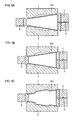
- FIGS. 5A and 5B are cross-sectional views showing an example of the shape of a tapered pipe constituting a profile element pipe for hydraulic bulging according to the present invention.
- FIGS. 6A and 6B are views illustrating the entire configuration of the profile element pipes according to the present invention, and particularly FIG. 6A shows an example in which parallel parts each having a circular cross section are formed on both ends of the tapered part having circular cross sections and FIG. 6B shows an example in which parallel parts each having a rectangular cross section are formed on both ends of the tapered part having rectangular cross sections.
- FIGS. 7A and 7B are views illustrating the entire configuration of other profile element pipes according to the present invention, and show examples having a transitional part between a parallel part on the large diameter side and a central tapered part.
- FIGS. 8A to 8C are views explaining a method of producing the profile element pipe according to the present invention, having a parallel part on the end portion of a large diameter side desired, where FIG. 8A is an entire perspective view, FIG. 8B is a developed view and FIG. 8C is a view showing a trapezoidal shape similar to the developed view shown in FIG. 8B .
- FIGS. 9A to 9C are views showing another example of the profile element pipe according to the present invention along with a pressing tool used in the example, where FIG. 9A is an entire perspective view, FIG. 9B is an enlarged view of the pressing tool on the small diameter side and FIG. 9C is an enlarged view of the pressing tool, which also serves as a small diameter side sealing tool used in the profile element pipe.
- FIGS. 10A to 10C are views showing shapes of end surfaces of the profile element pipe of the present invention used in case where a small diameter side of a hydraulically bulged product has a rectangular cross section
- FIG. 10A is a cross-sectional view of the pipe at a position away from the pipe end on the small diameter side by ⁇ L+L 0
- FIG. 10C is a cross-sectional view of the end portion
- FIG. 10B is a cross-sectional view at an arbitrary intermediate position of the pipe.
- FIGS. 11A to 11C are views showing shapes of end surfaces of the profile element pipe of the present invention used in case where a large diameter side of a hydraulically bulged product has a rectangular cross section, and particularly FIG. 11A is a cross-sectional view at a position away from the pipe end on the large diameter side by ⁇ L′+L 0 ′, FIG. 11C is a cross-sectional view of the end portion of the pipe, and FIG. 11B is a cross-sectional view at the arbitrary intermediate position of the pipe.
- FIGS. 12A to 12C are views illustrating cross-sectional shapes in case that hydraulically bulged products have trapezoidal cross-sections.
- FIGS. 13A to 13C are views illustrating cross-sectional shapes in case that hydraulically bulged products have L-shaped cross-sections.
- FIGS. 14A to 14C are views explaining a first example of a method of the present invention, and shows the case that a parallel part of an end portion of profile element pipe is formed prior to hydraulic bulging, where FIG. 14A is a cross-sectional view showing of a state of setting a tapered pipe on dies, FIG. 14B is a cross-sectional view showing a state where the parallel part was formed before hydraulic bulging, and FIG. 14C is a cross-sectional view showing a state where hydraulic bulging has been completed.
- FIGS. 15A to 15C are views showing relationships among an upper die on the small diameter side, a pressing tool also serving as a sealing tool and the end portion of profile element pipe, where FIGS. 15A to 15C are views elaborating on FIGS. 14A to 14C in terms of the dimensional parameter.
- FIGS. 16A to 16C are views showing relationships among an upper die on the large diameter side, the pressing tool also serving as a sealing tool and the end portion of profile element pipe, where FIGS. 16A to 16C are views elaborating on FIGS. 14A to 14C in terms of the dimensional parameter.
- FIGS. 17A to 17C are views explaining a second example of the method of the present invention, and show a case where the parallel part of the end portion of profile element pipe is formed before setting the pipe on a die.
- FIG. 17A is a cross-sectional view showing a state of setting the profile element pipe on the die
- FIG. 17B is a cross-sectional view showing a state before hydraulic bulging
- FIG. 17C is a cross-sectional view showing a state after hydraulic bulging.
- FIGS. 18A to 18C are views explaining a third example of the method of the present invention, and show another example of the case where the parallel part of the end portion of profile element pipe is formed before setting the pipe on the die.
- FIGS. 18A to 18C are the same as in the case of FIGS. 17A to 17C .
- FIGS. 19A to 19C are explanatory views showing a fourth example of the method of the present invention, and show a configuration example in which an inner cavity of the parallel part at the large diameter side is axially monotonously increased with reference to the pipe-end of the large diameter side.
- FIGS. 19A to 19C are the same as in the case of FIG. 17A to 17C .
- FIGS. 20A to 20D are views showing configuration examples of the pressing tool, which is a component constituting the hydraulic bulging device of the present invention, also serving as a sealing tool.
- FIGS. 5A to 5B are cross-sectional views showing an example of the shape of tapered pipe constituting a profile element pipe of the present invention.
- a profile element pipe 11 for hydraulic bulging of the present invention is a profile element pipe to be provided for hydraulic bulging, has a peripheral length with an outer diameter gradually increasing or decreasing over axial length from one axial side toward the other thereof and forms parallel parts 11 a , 11 b on at least one pipe-end (both pipe ends of a small diameter side and a large diameter side have parallel parts in the examples shown in FIGS. 5A and 5B ).
- the parts 11 a and 11 b are considered to be end portions of the profile element pipe that are parallel to each other since they are each aligned with an axis of the profile element pipe 11 .
- the profile element pipe has a tapered body portion between its ends.
- the tapered body portion is shown between the two parallel parts 11 a and 11 b .
- the parallel parts 11 a and 11 b diverge from this taper by reason of being parallel to each other and the longitudinal axis of the profile element pipe 11 .
- axial pressing or pushing involves applying an axially pressing force on the ends of the profile element pipe using pressing tools.
- the pressing tools also function to seal the ends of the profile element pipe so that the profile element pipe can be internal pressurized for hydraulic bulging.
- the parallel parts 11 a and 11 b engage the pressing tools in a first length to form a seal.
- the tools move a second length during the pressing step that causes metal flow.
- the length of the parallel part on the profile element pipe can be such that it exceeds the length of the parallel part that is in contact with the pressing tool when the pressing tool is engaged the parallel part for sealing and the distance the pressing tool moves during the axially pressing step.
- the control of the length of the parallel part in this manner ensures that the sealing function is not compromised.
- FIGS. 6A and 6B are views illustrating the entire configuration of profile element pipe according to the present invention, where FIG. 6A shows an example in which parallel parts each having a circular cross section are formed on both ends of tapered part having circular cross sections and FIG. 6B shows an example in which parallel parts having a rectangular cross section are formed on both ends of the tapered part having rectangular cross sections.
- FIG. 6A shows the rudimental basic form, in which parallel parts 11 a and 11 b each having a circular cross-section are formed on both ends of tapered part having circular cross-sections.
- FIG. 6B is an example in which parallel parts 11 a and 11 b each having a rectangular cross-section are formed on both ends of tapered part having rectangular cross-sections.
- the parallel parts 11 a and 11 b have a cross-section shown in FIG. 10A to be described later on a small diameter side 11 a and have a cross-section shown in FIG. 11C to be described later on a large diameter side 11 b over the entire length.
- FIGS. 7A and 7B are views illustrating the entire configurations of other profile element pipes according to the present invention, and show examples having a transitional portion between a parallel part on the large diameter side and a central tapered part.
- FIG. 7A shows a view in which parallel parts 11 a and 11 b each having a circular cross section are formed on both ends of a tapered part having a circular cross section and a transition portion 11 c is provided between the large diameter side parallel part 11 b and the central tapered part.
- FIG. 7B shows a view in which parallel parts 11 a and 11 b each having a rectangular cross section are provided on both ends of a tapered part having a rectangular cross section and a transition portion 11 c is also provided between the large diameter side parallel part 11 b and the central tapered part.
- FIGS. 6B and 7B although the parallel parts 11 a and 11 b formed on the both ends, each of whose shapes is merely a rectangular cross section, are shown, the shapes of the parallel parts 11 a and 11 b can be a trapezoidal cross section as shown in FIGS. 12A to 12C to be described later, an L-shaped cross-section as shown in FIGS. 13A to 13C to be described later, a polygonal cross section not shown or the like.
- the central tapered part also having rectangular cross sections
- the central part is not particularly required to have rectangular cross sections and they may be a circular cross section as shown in FIGS. 6A and 7A .
- the central part may be subjected to bending or to pressing from upper and lower sides as well as from right and left sides so that a profile element pipe can be facilitated to be inserted into a hydraulic bulging die.
- FIGS. 8A to 8C are views explaining a method of producing the profile element pipe according to the present invention having a parallel part on end portion of a large diameter side, and particularly FIG. 8A is an entire perspective view, FIG. 8B is a developed view and FIG. 8C is a view showing a trapezoidal shape similar to the developed view shown in FIG. 8B .
- a method of producing a profile element pipe 11 according to the present invention having a parallel part 11 b on a large diameter side end portion of a tapered part having a circular cross-section as shown in FIG. 8A will be described as follows.
- a profile element pipe 11 having a parallel part 11 b on the large diameter side end portion can be obtained as shown in FIG. 8A .
- FIG. 8C FIG. 8B is shown in addition by broken lines and a trapezoidal shape which is close to this is shown by solid lines.
- the most simple method for producing the profile element pipe is a method comprising the process of simply bending a plate having a developed shape of a profile element pipe 11 according to the present invention to join with ends
- other methods of producing profile element pipes 11 according to the present invention having shapes shown in FIGS. 6A and 6B and FIGS. 7A and 7B besides the above-mentioned method will be described.
- the profile element pipe 11 according to the present invention can be obtained by expanding an inner diameter on the small diameter side and by reducing an outer diameter on the large diameter side using “a merely tapered pipe” as a material, for example. Further, in case of the shape shown in FIG. 6B , it can be obtained by stamping the central body part in addition to the above-mentioned pre-forming.
- a merely tapered pipe means a material of a profile element pipe of the present invention and a tapered pipe in which a parallel part has not yet been formed on one pipe end or both pipe ends.
- the profile element pipe 11 according to the present invention can be obtained by expanding inner diameters on the small diameter side and the large diameter side using “a merely tapered pipe” as a material, for example. Further, in case of the shape shown in FIG. 7B , it can be obtained by stamping the central body part in addition to the above-mentioned working process.
- FIGS. 9A to 9C are views showing another example of the profile element pipe according to the present invention and axial pressing or pushing tool used in the example, where FIG. 9A is an entire perspective view, FIG. 9B is an enlarged view of the profile element pipe on the small diameter side and FIG. 9C is an enlarged view of the pushing tool, which also serves as a small diameter side sealing tool used in the pushing tool.
- FIGS. 9A to 9C an embodiment shown in FIG. 9A forms parallel parts 11 a and 11 b each having rectangular cross section at both ends of a tapered part having rectangular cross sections.
- rectangular cross sections having dimensions of substantially the same width and height as those of the product are formed on a portion corresponding to ⁇ l+L 0 in the small diameter side parallel part 11 a and on a portion corresponding to ⁇ l′+L 0 ′ in the large diameter side parallel part 11 b in the merely tapered pipe.
- FIGS. 10A to 10C are views showing shapes of end surfaces of the profile element pipe of the present invention used in case that a small diameter side of a hydraulically bulged product has a rectangular cross section
- FIG. 10A shows a cross-sectional view at a position away from the pipe end on the small diameter side by ⁇ l+L 0
- FIG. 10C shows a cross-sectional view of the end portion of the pipe
- FIG. 10B is a cross-sectional view at an arbitrary intermediate position of the pipe.
- the profile element pipe of FIG. 10A shows a polygonal cross section, i.e., a rectangular cross section, with a radius of curvature R formed where the sides of the polygon meet.
- FIG. 10A-10C show how the radius of curvature of the corner part decreases as measured along the length of the parallel part when starting at the end of the pipe, denoted by FIG. 10C , and terminating at the position away from the end of the pipe, denoted by FIG. 10A .
- the radius of curvature is made to vary, it could either increase or decrease along the parallel part length when starting from the end of the parallel part.
- FIGS. 10A to 10C are views explaining a shape in each of cross sections of the small diameter side parallel part 11 a of a profile element pipe of the present invention, and widths W 0 and heights H 0 in cross sections of FIGS. 10A to 10C are substantially constant. Further, the radius R of curvatures of corner part is gradually changed by previous forming.
- the radiuses of curvatures of four corner parts in each cross section were set as the same. However, it is not necessary that they are set to be the same, and different radiuses of curvatures at every corner part may be used.
- a peripheral length difference ⁇ d(x) at the position X away from a pipe end while setting a distance between both pipe-ends of a merely tapered pipe as a reference length is obtained from the following expression (2).
- D 0 denotes an outer diameter on the small diameter side
- D 0 ′ denotes an outer diameter on the large diameter side
- LT denotes a length of the tapered pipe.
- FIGS. 11A to 11C are views showing shapes of end surfaces of the profile element pipe of the present invention used in case that a large diameter side of a hydraulically bulged product has a rectangular cross section, where FIG. 11A is a cross-sectional view of a pipe at the position away from the pipe end on the large diameter side by ⁇ l′+L 0 ′, FIG. 11C is a cross-sectional view of the end portion of the pipe, and FIG. 11B is a cross-sectional view at the intermediate position of the pipe.
- FIGS. 11A to 11C are views explaining a shape in each cross section of the large diameter side parallel part 11 b of the profile element pipe of the present invention, and widths W 0 ′ and heights H 0 ′ in cross sections in FIGS. 11A to 11C are substantially constant. Further, the radius R′ of curvatures of corner part is gradually changed by pre-forming.
- the peripheral length difference ⁇ d(x) at a position X away from the edge of pipe end while setting a distance between both pipe ends of a merely tapered pipe as a reference length is obtained from the following expression (2′).
- D 0 denotes an outer diameter on the small diameter side
- D 0 ′ denotes an outer diameter on the large diameter side
- LT denotes a length of the tapered pipe.
- the dimension of the radius R′(x) of curvature of corner part is varied at axial positions in accordance with the peripheral length difference ⁇ d(x) as shown in FIGS. 11A to 11C , so that the suitable shape of the pipe can be determined.
- the profile element pipe of the present invention are not limited thereto.
- a combined rectangular shape or a polygonal shape can be adopted and extremely stable axial pressing can be performed during hydraulic bulging.
- FIGS. 12A to 12C are views illustrating cross-sectional shapes in case that hydraulically bulged products have trapezoidal cross-sections.
- FIGS. 13A to 13C are views illustrating cross-sectional shapes in case that hydraulically bulged products have L-shaped cross-sections.
- FIGS. 12 and 13 show examples of cross-sectional shapes of pre-formed pipes on the large diameter side, wherein (a) is a cross sectional view at a position away from the large diameter side pipe end by ⁇ l′+L 0 ′ in the axial direction, (c) is a cross sectional view of the pipe end portion, and (b) is a cross sectional view at an intermediate position therebetween.
- FIGS. 14A to 14C are views explaining a first example of a method of the present invention, and shows the case that a parallel part of an end portion of profile element pipe is formed prior to hydraulic bulging
- FIG. 14A is a cross-sectional view showing of a state of setting a tapered pipe on a die
- FIG. 14B is a cross-sectional view showing a state where the parallel part was formed before hydraulic bulging
- FIG. 14C is a cross-sectional view showing a state where hydraulic bulging has been completed.
- the end portion of the profile element pipe is expanded by the pressing tool also serving as seal tool and reshaping tool and is reshaped in accordance with the dies surrounding the profile element pipe.
- a pressing tool (if one end of the profile element pipe is open) applies an axial force on the end part of the pipe to cause metal flow and assist in the bulging of the profile element pipe.
- the pressing tool engages the parallel part for sealing an interior of the profile element pipe. If the profile element pipe has parallel parts on each end, pressing tools are provided for each parallel part.
- Another aspect of the inventive method is the formation of the parallel part or parts by the pressing tool(s) prior to the bulging and axially pressing steps and this is also explained in more detail below.
- FIGS. 15A to 15C are views showing relationships among an upper die on the small diameter side, a pressing tool also serving as a sealing and reshaping tool and the end portion of the profile element pipe, where FIGS. 15A to 15C are views elaborating on FIGS. 14A to 14C .
- FIGS. 16A to 16C are views showing relationships among an upper die on the large diameter side, the pressing tool also serving as a sealing and reshaping tool and the end portion of the profile element pipe, where FIGS. 16A to 16C are views elaborating on FIGS. 14A to 14C .
- FIGS. 17A to 17C are views explaining a second example of the method of the present invention, and show the case that the parallel part of the end portion of the profile element pipe is formed before setting the pipe on a die.
- FIG. 17A is a cross-sectional view showing a state of setting the profile element pipe on the die
- FIG. 17B is a cross-sectional view showing a state before hydraulic bulging
- FIG. 17C is a cross-sectional view showing a state after hydraulic bulging.
- FIGS. 18A to 18C are views explaining a third example of the method of the present invention, and shows another example of the case that the parallel part of the end portion of profile element pipe is formed before setting the pipe on the die.
- FIG. 18A is a cross-sectional view showing a state of setting the profile element pipe on the die
- FIG. 18B is a cross-sectional view showing a state before hydraulic bulging
- FIG. 18C is a cross-sectional view showing a state after hydraulic bulging.
- the hydraulic bulging device of the present invention includes an upper die 12 and a lower die 13 forming a cavity as shown in FIGS. 14 , 17 and 18 , for example, and pressing tools 14 and 15 which also serving as sealing tools, front end portions of which are inserted into the respective end portions of both dies 12 and 13 .
- the both dies 12 and 13 as well as the pressing tools 14 and 15 are constituted so that both ends of the profile element pipe 11 of the present invention are sandwiched and held by them.
- any one of the pressing tools is provided with a filling hole for working liquid, and an inner surface of at least one end side (both of the small diameter side and a large diameter side of the die have parallel parts in examples shown in FIGS. 14 , 17 and 18 ) and an outer surface of the pressing tool corresponding to the inner surface of this end surface are provided with parallel parts 12 a , 12 b , 13 a , 13 b , 14 a and 15 a , respectively.
- the parallel parts 14 a and 15 a of the outer surfaces of the pressing tools 14 , 15 restrain the element pipe from the inner surfaces thereof during axial pressing so that smooth deformation can be made.
- the amount of axial pressing on the small diameter part side is defined as ⁇ l
- the amount of axial pressing on the large diameter part side is defined as ⁇ l′
- the length required for sealing the small diameter part side is defined as L 0
- the length required for sealing the large diameter part side is defined as L 0 ′
- lengths of the parallel parts 12 a , 12 b , 13 a and 13 b provided on an inner surface of at least one end side are desirably ⁇ l+L 0 or more in case of the small diameter side parallel parts, and ⁇ l′+L 0 ′ or more in case of the large diameter side parallel parts.
- lengths of the parallel parts 14 a and 15 a of the pressing tools 14 and 15 corresponding to the parallel parts 12 a , 12 b , 13 a and 13 b provided on dies 12 , 13 are desirably ⁇ l+L 0 or more in case of the small diameter side parallel parts, and L 0 ′ or more in case of the large diameter side parallel parts.
- a front end portion of the pressing tool 14 ( 15 ) also serving as a sealing tool on the small diameter side (large diameter side) must be designed to be inserted into a small diameter side end portion (large diameter side end portion) of a merely tapered pipe PT as a material for the profile element pipe 11 or a profile element pipe 11 .
- the parallel part 14 a ( 15 a ) does not form a gap between a leading edge of the parallel part 14 a ( 15 a ) and the inner surface of the profile element pipe 11 at the completion of axial pressing.
- a pressing tool also serving as a sealing tool must satisfy the following conditions A and B.
- a peripheral length SD 0 of an envelope on the front end in which a locally concave portion was neglected satisfies the following expression (3).
- a peripheral length SD 0 ′ of an envelope on the front end in which a locally concave portion was neglected satisfies the following expression (4).
- a peripheral length SD 0 of a front end portion satisfies the following expression (5) SD0 ⁇ Peripheral length SD of the parallel part 14 a (5)
- a peripheral length SD 0 ′ of a front end portion satisfies the following expression (6) SD0′ ⁇ Peripheral length SD′ of the parallel part 15 a (6)
- a merely tapered pipe PT which is a source material for the profile element pipe 11 of the present invention, is set in a pair of dies 12 and 13 for a hydraulic bulging device as shown in FIG. 14A , for example.
- pressing tools 14 and 15 also serving as sealing tools are moved in the axial direction to form parallel parts 11 a and 11 b on an end or both ends of the tapered pipe PT sandwiched by the dies 12 , 13 and the pressing tools 14 , 15 as shown in FIG. 14B so that a profile element pipe 11 according to the present invention is formed.
- the pressing tools 14 and 15 it is not necessary to synchronize the timing of axial pressing of the profile element pipe 11 by the pressing tools 14 and 15 .
- the pressing tool 15 pushes the profile element pipe 11 to some extent pushing by the pressing tool 14 may be started.
- the axial pressing timing whereby the profile element pipe 11 is held stably in the dies 12 and 13 may be selected.
- the pressing tools 14 and 15 can be smoothly inserted into the tapered pipe TP.
- FIGS. 19A to 19C are explanatory views showing a fourth example of the method of the present invention, and shows a configuration example in which an inner cavity of the large diameter side parallel part is axially monotonously increased with reference to an end of the large diameter of the pipe.
- FIG. 19A is a cross-sectional view showing a state of setting a tapered pipe on the die
- FIG. 19B is a cross-sectional view showing a state where a parallel part is formed before hydraulic bulging
- FIG. 19C is a cross-sectional view of a state after hydraulic bulging.
- FIGS. 19A to 19C has a different form from examples shown in FIGS. 14 , 17 and 18 . That is the example shown in FIGS. 19A to 19C also has parallel parts 12 a , 12 b , 13 a and 13 b on both end portions of both dies 12 and 13 . However, a cavity inside the large diameter side parallel parts 12 b and 13 b of dies 12 and 13 is monotonously decreased in the axial direction with reference to the large diameter end without locally narrowing a portion of the cavity as in the examples shown in FIG. 14 and the like.
- a shape of the cavity formed in the dies 12 and 13 is preferably designed to a shape shown in FIG. 19 .
- cross-sectional shapes of end portions of a product are similar to a rectangle, a combined rectangle, and a shape of a polygon and the like which are intricate shapes in many cases.
- FIGS. 18A to 18C are views showing an example of a case that the profile element pipe 11 of the present invention shown in FIG. 9A .
- the profile element pipe 11 shown in FIG. 9A is set in dies 12 and 13 .
- FIG. 9B shows an enlarged view of the small diameter side profile element pipe 11 of the present invention.
- cross sectional shapes of the small diameter side parallel parts 11 a are as shown in FIGS. 10A to 10C .
- FIG. 9C shows the pressing tool 14 also serving as a small diameter side sealing tool.
- the parallel part 14 a shown in FIG. 9C has a width of W 0 ⁇ 2t, a height of H 0 ⁇ 2t, and a radius of curvature in a corner part of R 1 .
- the pressing tools 14 and 15 are pressed into end portions from a state shown in FIG. 18A , the forming of end portions of the profile element pipe 11 is completed at the stage of FIG. 18B , so that the profile element pipe 11 shown in FIG. 9B can be obtained while sealing of the working liquid has been fully held with the internal pressure loaded.
- the pressing tools 14 and 15 are moved in the axial direction so that a hydraulically bulged product 17 according to the method of the present invention can be obtained.
- the forming of the parallel parts 11 a and 11 b of pipe ends which is performed prior to hydraulic bulging may be carried out at pre-forming or at a stage prior to the pre-forming.
- the forming can be implemented by existing working methods such as reducing, hole expanding, swaging, spinning or a combination thereof.
- FIGS. 20A to 20D are views showing configuration examples of the pressing tool, which is a component constituting the hydraulic bulging device, also serving as a sealing and reshaping tool.
- FIG. 20A is a configuration example of sealing the device with an end surface 14 b or 15 b , which comes into contact with end surfaces of the profile element pipe 11
- FIG. 20B is also a configuration example in which a protrusion 14 c or 15 c is provided on the end surface 14 b or 15 b respectively
- FIG. 20C is a configuration example in which steps 14 d and 15 d are provided on boundary parts between the parallel part 14 a or 15 a and the end surface 14 b or 15 b
- FIG. 20D shows a configuration example in which an O ring 18 is provided on the parallel part 14 a or 15 a.
- FIGS. 20A to 20D satisfies the relationships between the parallel parts 14 a , 15 a and a peripheral length of a front end shown by the expressions (3) to (6).
- the pressing tool has only to be adapted to any one side, and the other side may be adapted to, for example, a non axial pressing type as shown in FIG. 1 , which is conventionally applied. Since effects of axial pressing are varied by the shapes of products, the scope of application of the present invention may be determined case by case.
- a welded pipe by combining merely tapered pipes and a pipe in combination of a tapered pipe with a general straight pipe can also be applied as source materials of the profile element pipes 11 of the present invention because each end portion of the pipe can be closely approximated to the relevant part of a merely tapered pipe.
- a hydraulic bulging method using the profile element pipe having a peripheral length with an outer diameter gradually increasing or decreasing from one axial side to the other thereof at least one end part of the profile element pipe to form parallel part being parallel to a longitudinal axis of the profile element pipe is reshaped, subsequently the profile element pipe is, hydraulically bulged by pressurizing an interior of the profile element pipe and reshaping of the profile element pipe and applying an axial force to the end of the parallel part using a tool adapted to engage the parallel part for metal flow and reshaping to form a bulged pipe with the parallel part sealing an interior of the profile element pipe.
- a profile element pipe having a parallel part formed on at least one end of the profile element pipe, is provided and then the profile element pipe is hydraulically bulged by pressurizing an interior of the profile element pipe and reshaping of the profile element pipe and applying an axial force to the end of the parallel part using a tool adapted to engage the parallel part for metal flow and reshaping to form a bulged pipe.
- pressing tools serves as seal tools and reshaping tools for holding a profile element pipe having a peripheral length with an outer diameter gradually increasing or decreasing from one axial side to the other thereof, while sandwiching the profile element pipe with said dies, wherein a filling hole for working liquid is provided at any one of said pressing tools and parallel parts are provided on at least one end-portion inner surface of said dies and an outer surface of said pressing tool corresponding to this end-portion inner surface, respectively.
Landscapes
- Physics & Mathematics (AREA)
- Fluid Mechanics (AREA)
- Engineering & Computer Science (AREA)
- Mechanical Engineering (AREA)
- Shaping Metal By Deep-Drawing, Or The Like (AREA)
Abstract
Description
R0≧R(x)≧R1 (1)
Δd(x)=π·(D0′−D0)·X/LT (2)
R0′≧R′(x)≧R1′ (1′)
Δd(x)=π·(D0′−D0)·X/LT (2′)
SD0≦(DO−2t/cos θ)π (3)
SD0′≦(DO′−2t/cos θ)π (4)
SD0≦Peripheral length SD of the
SD0′≦Peripheral length SD′ of the
Claims (19)
Priority Applications (1)
| Application Number | Priority Date | Filing Date | Title |
|---|---|---|---|
| US12/003,389 US7827839B2 (en) | 2002-11-08 | 2007-12-21 | Profile element pipe for hydraulic bulging, hydraulic bulging device using the element pipe, hydraulic bulging method using the element pipe, and hydraulically bulged product |
Applications Claiming Priority (6)
| Application Number | Priority Date | Filing Date | Title |
|---|---|---|---|
| JP2002-325801 | 2002-11-08 | ||
| JP2002325801 | 2002-11-08 | ||
| PCT/JP2003/014284 WO2004041458A1 (en) | 2002-11-08 | 2003-11-10 | Deformed element pipe for hydraulic bulging, hydraulic bulging device using the element pipe, hydraulic bulging method using the element pipe, and hydraulic-bulged product |
| US11/123,196 US20050257587A1 (en) | 2002-11-08 | 2005-05-06 | Profile element pipe for hydraulic bulging, hydraulic bulging device using the element pipe, hydraulic bulging method using the element pipe, and hydraulically bulged product |
| US11/806,531 US20070234771A1 (en) | 2002-11-08 | 2007-06-01 | Method of Hydraulic bulging and shaft pressing profile element pipe to make hydraulically bulged product |
| US12/003,389 US7827839B2 (en) | 2002-11-08 | 2007-12-21 | Profile element pipe for hydraulic bulging, hydraulic bulging device using the element pipe, hydraulic bulging method using the element pipe, and hydraulically bulged product |
Related Parent Applications (1)
| Application Number | Title | Priority Date | Filing Date |
|---|---|---|---|
| US11/806,531 Continuation-In-Part US20070234771A1 (en) | 2002-11-08 | 2007-06-01 | Method of Hydraulic bulging and shaft pressing profile element pipe to make hydraulically bulged product |
Publications (2)
| Publication Number | Publication Date |
|---|---|
| US20080178650A1 US20080178650A1 (en) | 2008-07-31 |
| US7827839B2 true US7827839B2 (en) | 2010-11-09 |
Family
ID=39666421
Family Applications (1)
| Application Number | Title | Priority Date | Filing Date |
|---|---|---|---|
| US12/003,389 Expired - Fee Related US7827839B2 (en) | 2002-11-08 | 2007-12-21 | Profile element pipe for hydraulic bulging, hydraulic bulging device using the element pipe, hydraulic bulging method using the element pipe, and hydraulically bulged product |
Country Status (1)
| Country | Link |
|---|---|
| US (1) | US7827839B2 (en) |
Cited By (3)
| Publication number | Priority date | Publication date | Assignee | Title |
|---|---|---|---|---|
| US20110023568A1 (en) * | 2009-07-31 | 2011-02-03 | Honda Motor Co., Ltd. | Apparatus and method of hot bulge forming, and product formed by hot bulge forming |
| US20170173655A1 (en) * | 2015-12-21 | 2017-06-22 | Harbin Institute Of Technology (Weihai) | Process for forming hollow member with complicated cross-section |
| US12516910B2 (en) | 2018-05-15 | 2026-01-06 | Agency Arms, Llc | Firearm sight mounting plate assembly |
Families Citing this family (7)
| Publication number | Priority date | Publication date | Assignee | Title |
|---|---|---|---|---|
| US8365767B2 (en) * | 2006-04-20 | 2013-02-05 | Masco Corporation Of Indiana | User interface for a faucet |
| CN102294407B (en) * | 2010-06-22 | 2013-09-04 | 陈永华 | Negative oil pressure pipe rectifying device |
| FR3004368B1 (en) * | 2013-04-15 | 2015-09-25 | Aircelle Sa | SOLDERING WITHOUT TOOLS |
| DE102015012665A1 (en) | 2015-09-30 | 2017-03-30 | Interroll Holding Ag | Conveyor belt pulley, method for making a pulley tube and deformation tool |
| CZ2016846A3 (en) * | 2016-12-31 | 2018-07-11 | Západočeská Univerzita V Plzni | A method of hot production of hollow bodies from martensitic-austenitic AHS steels using internal overpressure with heating in the tool |
| US11779985B1 (en) * | 2020-11-15 | 2023-10-10 | Herbert U. Fluhler | Fabricating method for low cost liquid fueled rocket engines |
| CN117161196A (en) * | 2023-10-11 | 2023-12-05 | 上海飞挺管业制造有限公司 | Super large diameter Y-type reducing tee reducing diameter forming mechanical device based on cold extrusion |
Citations (25)
| Publication number | Priority date | Publication date | Assignee | Title |
|---|---|---|---|---|
| US3486703A (en) | 1966-10-03 | 1969-12-30 | Whirlpool Co | Food waste grinder hopper |
| US3572073A (en) | 1969-03-10 | 1971-03-23 | Walter B Dean | Method of shaping a thin-walled body |
| JPS5147567A (en) | 1974-10-23 | 1976-04-23 | Honda Motor Co Ltd | Sozaikantanbuno ekiatsuseikeiho |
| US3958437A (en) | 1975-01-24 | 1976-05-25 | Seew Barorian | Process for manufacturing metal poles |
| JPS5273168A (en) | 1975-12-15 | 1977-06-18 | Shinwa Baruji Kk | Method of producing couplings |
| JPS6137327A (en) | 1984-07-30 | 1986-02-22 | Hitachi Ltd | How to make a tapered pipe |
| US5203190A (en) | 1990-05-30 | 1993-04-20 | Sivco, Inc. | Method and apparatus for making a hydrocyclone separation chamber |
| US5333775A (en) | 1993-04-16 | 1994-08-02 | General Motors Corporation | Hydroforming of compound tubes |
| US5419791A (en) | 1993-07-21 | 1995-05-30 | Folmer; Carroll W. | Method of heat assisted sheet metal forming in 360 degree shapes |
| US5445001A (en) | 1994-08-10 | 1995-08-29 | General Motors Corporation | Method and apparatus for forming and cutting tubing |
| JPH0939864A (en) | 1995-07-28 | 1997-02-10 | Honda Motor Co Ltd | Manufacturing method of fuel tanks for motorcycles |
| JP2000045767A (en) | 1998-07-27 | 2000-02-15 | Calsonic Corp | Bulge forming die and bulge forming method |
| WO2000010748A1 (en) | 1998-08-25 | 2000-03-02 | R.J. Tower Corporation | Method of hydroforming tubular members |
| JP2000202535A (en) | 1999-01-14 | 2000-07-25 | Nissan Motor Co Ltd | Hydraulic forming nozzle and hydraulic forming device |
| JP2001321842A (en) | 2000-05-10 | 2001-11-20 | Mitsubishi Motors Corp | Hydroformed molded article, method of forming the same, and vehicle body member using the hydroformed molded article |
| US6332346B2 (en) | 1998-02-18 | 2001-12-25 | Nippon Sanso Corporation | Metal vessel and a fabrication method for the same |
| JP2002035855A (en) | 2000-07-18 | 2002-02-05 | Nissan Motor Co Ltd | Method of forming overhang by hydroforming method |
| JP2002045924A (en) | 2000-08-08 | 2002-02-12 | Sumitomo Metal Ind Ltd | Hydroformed molded article, method of forming the same, and vehicle body member using the hydroformed molded article |
| US20020162224A1 (en) | 2001-05-01 | 2002-11-07 | Gianfranco Gabbianelli | Hydroformed vehicle frame assembly and method |
| JP2003001336A (en) | 2001-06-25 | 2003-01-07 | Aisin Takaoka Ltd | Method for manufacturing eccentric tube using hydroform method |
| US6519855B1 (en) | 1999-08-31 | 2003-02-18 | Dana Corporation | Method of manufacturing a vehicle body and frame assembly |
| US6826943B2 (en) * | 2000-08-29 | 2004-12-07 | Hydro Alumunium Deutschland Gmbh | Process for forming tube-shaped hollow bodies made of metal |
| WO2005018846A1 (en) | 2003-08-13 | 2005-03-03 | Thyssenkrupp Steel Ag | Internal high pressure shaping method for shaping conical metal tubes |
| US6941786B1 (en) | 2004-03-25 | 2005-09-13 | Ford Global Technologies, Llc | Component specific tube blanks for hydroforming body structure components |
| US7013697B2 (en) * | 2001-07-05 | 2006-03-21 | Magna Structural Systems, Inc. | Method for expanding a tubular blank |
Family Cites Families (1)
| Publication number | Priority date | Publication date | Assignee | Title |
|---|---|---|---|---|
| US162224A (en) * | 1875-04-20 | Improvement in breech-loading fire-arms |
-
2007
- 2007-12-21 US US12/003,389 patent/US7827839B2/en not_active Expired - Fee Related
Patent Citations (28)
| Publication number | Priority date | Publication date | Assignee | Title |
|---|---|---|---|---|
| US3486703A (en) | 1966-10-03 | 1969-12-30 | Whirlpool Co | Food waste grinder hopper |
| US3572073A (en) | 1969-03-10 | 1971-03-23 | Walter B Dean | Method of shaping a thin-walled body |
| JPS5147567A (en) | 1974-10-23 | 1976-04-23 | Honda Motor Co Ltd | Sozaikantanbuno ekiatsuseikeiho |
| US3958437A (en) | 1975-01-24 | 1976-05-25 | Seew Barorian | Process for manufacturing metal poles |
| JPS5273168A (en) | 1975-12-15 | 1977-06-18 | Shinwa Baruji Kk | Method of producing couplings |
| JPS6137327A (en) | 1984-07-30 | 1986-02-22 | Hitachi Ltd | How to make a tapered pipe |
| US5203190A (en) | 1990-05-30 | 1993-04-20 | Sivco, Inc. | Method and apparatus for making a hydrocyclone separation chamber |
| US5333775A (en) | 1993-04-16 | 1994-08-02 | General Motors Corporation | Hydroforming of compound tubes |
| US5419791A (en) | 1993-07-21 | 1995-05-30 | Folmer; Carroll W. | Method of heat assisted sheet metal forming in 360 degree shapes |
| US5445001A (en) | 1994-08-10 | 1995-08-29 | General Motors Corporation | Method and apparatus for forming and cutting tubing |
| JPH0939864A (en) | 1995-07-28 | 1997-02-10 | Honda Motor Co Ltd | Manufacturing method of fuel tanks for motorcycles |
| US6332346B2 (en) | 1998-02-18 | 2001-12-25 | Nippon Sanso Corporation | Metal vessel and a fabrication method for the same |
| JP2000045767A (en) | 1998-07-27 | 2000-02-15 | Calsonic Corp | Bulge forming die and bulge forming method |
| WO2000010748A1 (en) | 1998-08-25 | 2000-03-02 | R.J. Tower Corporation | Method of hydroforming tubular members |
| US6216509B1 (en) | 1998-08-25 | 2001-04-17 | R.J. Tower Corporation | Hydroformed tubular member and method of hydroforming tubular members |
| EP1022073A1 (en) | 1999-01-14 | 2000-07-26 | Nissan Motor Company, Limited | Nozzle for hydrostatic forming and hydrostatic forming device using such a nozzle |
| US6266986B1 (en) | 1999-01-14 | 2001-07-31 | Nissan Motor Co., Ltd. | Nozzle for hydrostatic forming and hydrostatic forming system using same nozzle |
| JP2000202535A (en) | 1999-01-14 | 2000-07-25 | Nissan Motor Co Ltd | Hydraulic forming nozzle and hydraulic forming device |
| US6519855B1 (en) | 1999-08-31 | 2003-02-18 | Dana Corporation | Method of manufacturing a vehicle body and frame assembly |
| JP2001321842A (en) | 2000-05-10 | 2001-11-20 | Mitsubishi Motors Corp | Hydroformed molded article, method of forming the same, and vehicle body member using the hydroformed molded article |
| JP2002035855A (en) | 2000-07-18 | 2002-02-05 | Nissan Motor Co Ltd | Method of forming overhang by hydroforming method |
| JP2002045924A (en) | 2000-08-08 | 2002-02-12 | Sumitomo Metal Ind Ltd | Hydroformed molded article, method of forming the same, and vehicle body member using the hydroformed molded article |
| US6826943B2 (en) * | 2000-08-29 | 2004-12-07 | Hydro Alumunium Deutschland Gmbh | Process for forming tube-shaped hollow bodies made of metal |
| US20020162224A1 (en) | 2001-05-01 | 2002-11-07 | Gianfranco Gabbianelli | Hydroformed vehicle frame assembly and method |
| JP2003001336A (en) | 2001-06-25 | 2003-01-07 | Aisin Takaoka Ltd | Method for manufacturing eccentric tube using hydroform method |
| US7013697B2 (en) * | 2001-07-05 | 2006-03-21 | Magna Structural Systems, Inc. | Method for expanding a tubular blank |
| WO2005018846A1 (en) | 2003-08-13 | 2005-03-03 | Thyssenkrupp Steel Ag | Internal high pressure shaping method for shaping conical metal tubes |
| US6941786B1 (en) | 2004-03-25 | 2005-09-13 | Ford Global Technologies, Llc | Component specific tube blanks for hydroforming body structure components |
Cited By (4)
| Publication number | Priority date | Publication date | Assignee | Title |
|---|---|---|---|---|
| US20110023568A1 (en) * | 2009-07-31 | 2011-02-03 | Honda Motor Co., Ltd. | Apparatus and method of hot bulge forming, and product formed by hot bulge forming |
| US20170173655A1 (en) * | 2015-12-21 | 2017-06-22 | Harbin Institute Of Technology (Weihai) | Process for forming hollow member with complicated cross-section |
| US9808850B2 (en) * | 2015-12-21 | 2017-11-07 | Harbin Institute Of Technology (Weihai) | Process for forming hollow member with complicated cross-section |
| US12516910B2 (en) | 2018-05-15 | 2026-01-06 | Agency Arms, Llc | Firearm sight mounting plate assembly |
Also Published As
| Publication number | Publication date |
|---|---|
| US20080178650A1 (en) | 2008-07-31 |
Similar Documents
| Publication | Publication Date | Title |
|---|---|---|
| US20070234771A1 (en) | Method of Hydraulic bulging and shaft pressing profile element pipe to make hydraulically bulged product | |
| US7827839B2 (en) | Profile element pipe for hydraulic bulging, hydraulic bulging device using the element pipe, hydraulic bulging method using the element pipe, and hydraulically bulged product | |
| US4567743A (en) | Method of forming box-section frame members | |
| US7051768B2 (en) | Hydroform process and hydroform product | |
| JP3952991B2 (en) | Manufacturing method of piping having joint portions at both ends | |
| US6931906B2 (en) | Method and apparatus for cold forging a trailer hitch receiving housing | |
| JP5136998B2 (en) | Hydraulic bulge method and hydraulic bulge product | |
| GB2412341A (en) | Method and apparatus for joining plates by caulking | |
| US7225541B2 (en) | Method for producing hollow rack bar | |
| JP2760269B2 (en) | Manufacturing method of bulge-shaped piping | |
| US6763693B1 (en) | Method for shaping an initial profile or a similar workpiece using an internal high pressure and profile therefor | |
| US7484393B2 (en) | Profile mother pipe for hydraulic bulging, hydraulic bulging apparatus using the same, hydraulic bulging method, and hydraulic bulged product | |
| JP4060723B2 (en) | Hydraulic bulge processing apparatus and hydraulic bulge processing method | |
| US6675477B2 (en) | Method for manufacturing spool valve | |
| JPH0957380A (en) | Manufacture of cylindrical parts | |
| JP2005334941A (en) | Pipe-shaped product forming method and pipe-shaped product | |
| JP4360125B2 (en) | Molding method | |
| JP2005205488A (en) | Method for working metallic tube | |
| JP4234224B2 (en) | Groove machining method and manufacturing method for automobile steering main shaft | |
| JPH11208417A (en) | Steering shaft and method of manufacturing the same | |
| JP2847014B2 (en) | Gear material forging method | |
| JP3110302B2 (en) | Manufacturing method of drawn container | |
| WO2025134922A1 (en) | Metal component manufacturing method, and metal component | |
| JP2002192253A (en) | Hollow shaft with projection and manufacturing method thereof | |
| JP2006175521A (en) | Hydraulic bulge parts with flange |
Legal Events
| Date | Code | Title | Description |
|---|---|---|---|
| AS | Assignment |
Owner name: SUMITOMO PIPE AND TUBE CO., LTD., JAPAN Free format text: ASSIGNMENT OF ASSIGNORS INTEREST;ASSIGNORS:TOMIZAWA, ATSUSHI;KOJIMA, MASAYASU;REEL/FRAME:021768/0706;SIGNING DATES FROM 20080321 TO 20080325 Owner name: SUMITOMO METAL INDUSTRIES, LTD., JAPAN Free format text: ASSIGNMENT OF ASSIGNORS INTEREST;ASSIGNORS:TOMIZAWA, ATSUSHI;KOJIMA, MASAYASU;REEL/FRAME:021768/0706;SIGNING DATES FROM 20080321 TO 20080325 Owner name: MITSUBISHI JIDOSHAKOGYO KABUSHIKI KAISHA, JAPAN Free format text: ASSIGNMENT OF ASSIGNORS INTEREST;ASSIGNORS:TOMIZAWA, ATSUSHI;KOJIMA, MASAYASU;REEL/FRAME:021768/0706;SIGNING DATES FROM 20080321 TO 20080325 |
|
| STCF | Information on status: patent grant |
Free format text: PATENTED CASE |
|
| FEPP | Fee payment procedure |
Free format text: PAYOR NUMBER ASSIGNED (ORIGINAL EVENT CODE: ASPN); ENTITY STATUS OF PATENT OWNER: LARGE ENTITY |
|
| FPAY | Fee payment |
Year of fee payment: 4 |
|
| MAFP | Maintenance fee payment |
Free format text: PAYMENT OF MAINTENANCE FEE, 8TH YEAR, LARGE ENTITY (ORIGINAL EVENT CODE: M1552) Year of fee payment: 8 |
|
| AS | Assignment |
Owner name: NIPPON STEEL & SUMITOMO METAL CORPORATION, JAPAN Free format text: MERGER;ASSIGNOR:SUMITOMO METAL INDUSTRIES, LTD.;REEL/FRAME:049165/0517 Effective date: 20121003 Owner name: NIPPON STEEL CORPORATION, JAPAN Free format text: CHANGE OF NAME;ASSIGNOR:NIPPON STEEL & SUMITOMO METAL CORPORATION;REEL/FRAME:049257/0828 Effective date: 20190401 |
|
| FEPP | Fee payment procedure |
Free format text: MAINTENANCE FEE REMINDER MAILED (ORIGINAL EVENT CODE: REM.); ENTITY STATUS OF PATENT OWNER: LARGE ENTITY |
|
| LAPS | Lapse for failure to pay maintenance fees |
Free format text: PATENT EXPIRED FOR FAILURE TO PAY MAINTENANCE FEES (ORIGINAL EVENT CODE: EXP.); ENTITY STATUS OF PATENT OWNER: LARGE ENTITY |
|
| STCH | Information on status: patent discontinuation |
Free format text: PATENT EXPIRED DUE TO NONPAYMENT OF MAINTENANCE FEES UNDER 37 CFR 1.362 |
|
| FP | Lapsed due to failure to pay maintenance fee |
Effective date: 20221109 |