US7821146B2 - Parallel starting system having a low wiring expenditure - Google Patents
Parallel starting system having a low wiring expenditure Download PDFInfo
- Publication number
- US7821146B2 US7821146B2 US11/883,693 US88369305A US7821146B2 US 7821146 B2 US7821146 B2 US 7821146B2 US 88369305 A US88369305 A US 88369305A US 7821146 B2 US7821146 B2 US 7821146B2
- Authority
- US
- United States
- Prior art keywords
- engaging
- starters
- relay
- relays
- starter
- Prior art date
- Legal status (The legal status is an assumption and is not a legal conclusion. Google has not performed a legal analysis and makes no representation as to the accuracy of the status listed.)
- Expired - Lifetime, expires
Links
Images


Classifications
-
- F—MECHANICAL ENGINEERING; LIGHTING; HEATING; WEAPONS; BLASTING
- F02—COMBUSTION ENGINES; HOT-GAS OR COMBUSTION-PRODUCT ENGINE PLANTS
- F02N—STARTING OF COMBUSTION ENGINES; STARTING AIDS FOR SUCH ENGINES, NOT OTHERWISE PROVIDED FOR
- F02N11/00—Starting of engines by means of electric motors
-
- F—MECHANICAL ENGINEERING; LIGHTING; HEATING; WEAPONS; BLASTING
- F02—COMBUSTION ENGINES; HOT-GAS OR COMBUSTION-PRODUCT ENGINE PLANTS
- F02N—STARTING OF COMBUSTION ENGINES; STARTING AIDS FOR SUCH ENGINES, NOT OTHERWISE PROVIDED FOR
- F02N11/00—Starting of engines by means of electric motors
- F02N11/006—Starting of engines by means of electric motors using a plurality of electric motors
-
- F—MECHANICAL ENGINEERING; LIGHTING; HEATING; WEAPONS; BLASTING
- F02—COMBUSTION ENGINES; HOT-GAS OR COMBUSTION-PRODUCT ENGINE PLANTS
- F02N—STARTING OF COMBUSTION ENGINES; STARTING AIDS FOR SUCH ENGINES, NOT OTHERWISE PROVIDED FOR
- F02N11/00—Starting of engines by means of electric motors
- F02N11/08—Circuits specially adapted for starting of engines
- F02N11/087—Details of the switching means in starting circuits, e.g. relays or electronic switches
-
- F—MECHANICAL ENGINEERING; LIGHTING; HEATING; WEAPONS; BLASTING
- F02—COMBUSTION ENGINES; HOT-GAS OR COMBUSTION-PRODUCT ENGINE PLANTS
- F02N—STARTING OF COMBUSTION ENGINES; STARTING AIDS FOR SUCH ENGINES, NOT OTHERWISE PROVIDED FOR
- F02N11/00—Starting of engines by means of electric motors
- F02N11/10—Safety devices
-
- F—MECHANICAL ENGINEERING; LIGHTING; HEATING; WEAPONS; BLASTING
- F02—COMBUSTION ENGINES; HOT-GAS OR COMBUSTION-PRODUCT ENGINE PLANTS
- F02N—STARTING OF COMBUSTION ENGINES; STARTING AIDS FOR SUCH ENGINES, NOT OTHERWISE PROVIDED FOR
- F02N15/00—Other power-operated starting apparatus; Component parts, details, or accessories, not provided for in, or of interest apart from groups F02N5/00 - F02N13/00
- F02N15/02—Gearing between starting-engines and started engines; Engagement or disengagement thereof
- F02N15/04—Gearing between starting-engines and started engines; Engagement or disengagement thereof the gearing including disengaging toothed gears
- F02N15/06—Gearing between starting-engines and started engines; Engagement or disengagement thereof the gearing including disengaging toothed gears the toothed gears being moved by axial displacement
- F02N15/067—Gearing between starting-engines and started engines; Engagement or disengagement thereof the gearing including disengaging toothed gears the toothed gears being moved by axial displacement the starter comprising an electro-magnetically actuated lever
Definitions
- the present invention relates to a parallel starting system for starting internal combustion engines.
- FIG. 1 shows a parallel starting system from the related art having two starters 1 a , 1 b .
- Each of the starters includes a starter motor 2 a , 2 b and an engaging relay 4 a , 4 b which normally performs two functions.
- engaging relay 4 a , 4 b engages a pinion (not shown) driven by starter motor 2 a , 2 b with a ring gear of the internal combustion engine.
- engaging relay 4 a , 4 b closes a primary current path 8 via a normally open contact 5 a , 5 b when the pinion has engaged with the ring gear. This begins the actual starting operation.
- both starters 1 a , 1 b are interconnected in such a way that primary current path 8 to starter motors 2 a , 2 b is not closed until both pinions are engaged or both engaging relays 4 a , 4 b have completely pulled up.
- the two engaging relays 4 a , 4 b are in this case connected in parallel with respect to their control terminal and are connected to a terminal 50 which is connected to the starter switch (switch 6 ).
- the load terminals (terminals 30 , 30 b ) of engaging relays 4 a , 4 b are, however, interconnected in series. Terminal 30 of first starter 1 a is connected to a battery which supplies it a voltage U+.
- An object of the present invention is therefore to improve the switching reliability.
- a further object of the present invention is to develop a parallel starting system that can be wired using minimum complexity. This object is achieved according to the present invention.
- An important idea of the present invention is to separate the customary concatenation of the functions “engage” and “switch primary current” of conventional engaging relays and instead provide two relays, one of which (engaging relay) performs the function “engage” and the other (power relay) exclusively performs the function “switch primary current.”
- the engaging relay and the power relay are preferably designed as a structural unit together with the associated starter motor. This makes it possible to devise a parallel starting system that may be wired in a simple and low-cost manner and in which the power relay need not be designed for excessively high loads.
- the starters are preferably interconnected in such a way that the power relays do not switch the primary current to the starter motors until all engaging relays have pulled up (i.e., all pinions have engaged or the engaging springs are under tension).
- the engaging relays of two starters are connected with one another in series. This means the control terminal of the subsequent engaging relay is connected to the load terminal of the preceding engaging relay.
- the load terminals of the engaging relays are preferably connected to terminal 30 . If the engaging relays are connected in series, relatively high current flows to the second engaging relay, making a relatively thick connecting cable between the starters necessary.
- the engaging relays of two starters are connected in parallel with respect to their control terminals.
- the load terminals of the engaging relays are preferably connected in series, the first load terminal preferably being connected to terminal 30 .
- the load terminal of the last engaging relay is preferably interconnected with the control terminal ( 50 k ) of a power relay.
- the power relays are preferably connected in parallel. The advantage of the series connection of the load terminals is that the flow of current between two starters is substantially lower.
- each of the starters has its own power relay which switches the flow of current to the starter motor.
- at least one of the starters may also not have its own power relay ( FIG. 5 ). In this case, this engaging relay performs both functions, namely “engage” and “switch primary current.”
- a three-pole connection is provided between two starters connected in parallel. If the connecting cable of a starter has a plug connection, it is possible to connect a plurality of starters in a simple manner. When wiring the starters, it is only necessary to take note of the position of the starter in question in the chain of starters.
- FIG. 1 shows the electrical circuit diagram of a parallel starting system known from the related art.
- FIG. 2 shows the circuit diagram of a parallel starting system according to a first embodiment of the present invention.
- FIG. 3 shows the structural design of a parallel starting system according to FIG. 2 .
- FIG. 4 shows the circuit diagram of a parallel starting system according to a second embodiment of the present invention.
- FIG. 5 shows the circuit diagram of a parallel starting system according to a third embodiment of the present invention.
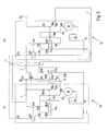
- FIGS. 6 a and 6 b show the circuit diagram of a parallel starting system having three starters.
- FIG. 2 shows a parallel starting system having two starters 1 a , 1 b .
- Each of starters 1 a , 1 b has a starting relay 13 a , 13 b , an engaging relay 4 a , 4 b , a power relay 12 a , 12 b and a starter motor 2 a , 2 b .
- the primary current of starter motors 2 a , 2 b is switched by power relays 12 a , 12 b .
- Engaging relays 4 a , 4 b are used only for engaging the pinion (not shown) with the ring gear and providing the starting current.
- starting relays 13 a , 13 b which are connected in parallel and connected to terminal 50 , pull in simultaneously and close associated switches 14 a , 14 b .
- engaging relays 4 a , 4 b are connected in series, i.e., the control terminal of engaging relay 4 b is connected with the load terminal (terminal 50 n ) of engaging relay 4 a . Therefore, switch 16 a of first engaging relay 4 a closes first and after that, switch 16 b of second engaging relay 4 b closes.
- the load terminals (terminal 50 m ) of the two engaging relays 4 a , 4 b are connected to terminal 30 .
- the load terminal (terminal 50 n ) of second engaging relay 4 b is interconnected with the control terminals (terminal 50 k ) of power relays 12 a , 12 b .
- Closing second switch 16 b therefore causes current to be supplied to the control terminals of power relays 12 a , 12 b .
- Power relays 12 a , 12 b are connected in parallel in this case.
- both associated switches 18 a , 18 b close approximately simultaneously and close the current path 8 between terminal 30 and terminal 45 of starter motors 2 a and 2 b , respectively.
- the internal combustion engine (not shown) is thus started approximately simultaneously by both starter motors 2 a , 2 b.
- the two starters 1 a , 1 b in this case are connected with one another by a three-pole electrical line 11 .
- a relatively high current of, e.g., 200 A, which is necessary for actuating relay 4 b flows between terminal 50 n and 50 i via control line 7 .
- this current is substantially reduced, making it possible to use a thinner cable.
- FIG. 3 shows the physical configuration of the parallel starting system of FIG. 2 .
- Each of starters 1 a , 1 b is designed as a structural unit, having a starter motor 2 a , 2 b , a starting relay 13 a , 13 b , an engaging relay 4 , and a power relay 12 a , 12 b .
- Starters 1 a , 1 b in this case are connected with one another via a three-pole electrical lead 11 .
- FIG. 4 shows a parallel starting system having two starters 1 a , 1 b that essentially have the same configuration as the starters of FIG. 2 .
- the load terminals (terminals 50 m , 50 n ) of engaging relays 4 a , 4 b are interconnected in series. As a result, only a substantially lower control current of approximately 20 A flows in control line 7 between terminals 50 n and 50 m , making it possible to use a substantially thinner line.
- Load switch 18 b of engaging relay 4 b is in turn connected to terminals 50 k of power relays 12 a , 12 b , which are connected in parallel.
- the control terminals (terminal 50 i ) of engaging relays 4 a , 4 b are connected in parallel and each of them is connected to terminal 30 via load contact 14 a , 14 b of the starting relays.
- FIG. 5 shows a third embodiment of a parallel starting system having two starters 1 a , 1 b connected in parallel similar to FIG. 2 .
- first starter 1 a has its own power relay 12 a .
- the primary current of starter motor 2 b is switched by combined engaging relay 4 b .
- Engaging relay 4 b in this case operates a switch 16 b which is connected between terminal 30 and terminal 45 of starter motor 2 b .
- contact 16 b is closed, current is supplied to control terminal 50 k of power relay 17 a .
- Contact 18 a switches the current for motor 2 a with a slight time delay with respect to 16 b .
- This version has the advantage that only one power relay 4 is needed. However, a slight time delay results when starting motors 2 a , 2 b , since engaging relay 4 b first switches on motor 2 b and only after that supplies current to series-connected power relay 12 a which then switches the primary current to motor 2 a.
- FIGS. 6 a and 6 b show a parallel connection of three starters 1 a , 1 b , and 1 c .
- Even more starters 1 could be connected in parallel.
- the internal configuration of all starters 1 is identical. Only the external wiring is configured differently depending on the position of starter 1 a , 1 b , or 1 c in the starter chain. In the case of a chain of n starters 1 , all of the starters located in the middle are configured identically with regard to their external wiring. Only first and last starters 1 a and 1 n must be wired differently in this case. This may be implemented in a manner which is simple and cost-effective in particular.
Landscapes
- Engineering & Computer Science (AREA)
- Chemical & Material Sciences (AREA)
- Combustion & Propulsion (AREA)
- Mechanical Engineering (AREA)
- General Engineering & Computer Science (AREA)
- Motor And Converter Starters (AREA)
Abstract
Description
- 1 Starter
- 2 Starter motor
- 3 Series winding
- 4 Engaging relay
- 5 Load switch of engaging relay 4
- 6 Starter switch
- 7 Control lead
- 8 Primary current lead
- 9 Ground wire
- 11 Connecting leads
- 12 Power relay
- 13 Starting relay
- 14 Load switch of the starting relay
- 15 Normally closed contact of the engaging relay.
- 16 Normally open contact of the engaging relay
- 17 Winding of the power relay
- 18 Load switch of
power relay 12
Claims (6)
Applications Claiming Priority (4)
| Application Number | Priority Date | Filing Date | Title |
|---|---|---|---|
| DE102005006248.2 | 2005-02-11 | ||
| DE102005006248A DE102005006248A1 (en) | 2005-02-11 | 2005-02-11 | Parallel start system with low wiring costs |
| DE102005006248 | 2005-02-11 | ||
| PCT/EP2005/056787 WO2006084521A1 (en) | 2005-02-11 | 2005-12-14 | Parallel starting system provided with a less-costly wiring |
Publications (2)
| Publication Number | Publication Date |
|---|---|
| US20080283012A1 US20080283012A1 (en) | 2008-11-20 |
| US7821146B2 true US7821146B2 (en) | 2010-10-26 |
Family
ID=35840345
Family Applications (1)
| Application Number | Title | Priority Date | Filing Date |
|---|---|---|---|
| US11/883,693 Expired - Lifetime US7821146B2 (en) | 2005-02-11 | 2005-12-14 | Parallel starting system having a low wiring expenditure |
Country Status (6)
| Country | Link |
|---|---|
| US (1) | US7821146B2 (en) |
| EP (1) | EP1851428B1 (en) |
| KR (1) | KR101050575B1 (en) |
| DE (1) | DE102005006248A1 (en) |
| ES (1) | ES2752734T3 (en) |
| WO (1) | WO2006084521A1 (en) |
Cited By (4)
| Publication number | Priority date | Publication date | Assignee | Title |
|---|---|---|---|---|
| US20120186550A1 (en) * | 2009-09-09 | 2012-07-26 | Simon Rentschler | Device for starting an internal combustion engine having a reduced number of control lines |
| CN102661224A (en) * | 2012-04-28 | 2012-09-12 | 北京佩特来电器有限公司 | Parallel connection starting device for starting internal combustion engine |
| US9157405B2 (en) | 2012-10-29 | 2015-10-13 | Mtu America Inc. | Starter motor testing device |
| US9869285B2 (en) | 2009-03-20 | 2018-01-16 | Robert Bosch Gmbh | Circuit configuration for starting an internal combustion engine and method of a starter control |
Families Citing this family (12)
| Publication number | Priority date | Publication date | Assignee | Title |
|---|---|---|---|---|
| DE102008004381A1 (en) * | 2008-01-15 | 2009-07-16 | Robert Bosch Gmbh | Parallel starting system |
| DE102008001750A1 (en) | 2008-05-14 | 2009-11-19 | Robert Bosch Gmbh | Starter for an internal combustion engine |
| DE102009001690A1 (en) | 2009-03-20 | 2010-09-23 | Robert Bosch Gmbh | Control for parallel mountable starters, circuitry, method and computer program product |
| DE102009028292A1 (en) * | 2009-08-06 | 2011-02-10 | Robert Bosch Gmbh | Device for starting an internal combustion engine of a motor vehicle with improved control unit |
| DE102010030398A1 (en) | 2010-06-23 | 2011-12-29 | Robert Bosch Gmbh | Starting device, starting system, method for operating a starting device and computer program product |
| JP5278390B2 (en) * | 2010-07-12 | 2013-09-04 | 日産自動車株式会社 | Engine starter for idle stop vehicle |
| US8776753B2 (en) * | 2011-12-30 | 2014-07-15 | Remy Technologies Llc | Dual synchronized starter motors |
| GB2509722B (en) * | 2013-01-10 | 2019-04-17 | Ford Global Tech Llc | A Method and Apparatus for Starting an Engine |
| US10001103B1 (en) * | 2016-12-15 | 2018-06-19 | Borgwarner, Inc. | System with multiple starters and smart relay |
| DE102017223106A1 (en) | 2017-12-18 | 2019-06-19 | Robert Bosch Gmbh | Starting device for internal combustion engines and method for operating such |
| US11293394B2 (en) * | 2019-01-16 | 2022-04-05 | Transportation IP Holdings, LLP | Starter motor system for a vehicle |
| DE102019109496A1 (en) * | 2019-04-10 | 2020-10-15 | Seg Automotive Germany Gmbh | Parallel starting system for starting an internal combustion engine |
Citations (17)
| Publication number | Priority date | Publication date | Assignee | Title |
|---|---|---|---|---|
| DE205963C (en) * | ||||
| GB451212A (en) | 1935-02-26 | 1936-07-31 | Scintilla Ltd | Electric starting installations for internal combustion engines |
| US2115671A (en) * | 1935-09-24 | 1938-04-26 | Bosch Robert | Starting apparatus for internal combustion engines |
| US2930901A (en) * | 1958-12-04 | 1960-03-29 | Walter R Freeman | Starting circuit |
| GB1462382A (en) | 1973-03-29 | 1977-01-26 | Cav Ltd | Starting mechanisms for internal combustion engines |
| US4170211A (en) * | 1977-09-02 | 1979-10-09 | Worthington Robert W | Combination AC and DC electrical starting motor for engines |
| DD144091A1 (en) | 1979-05-29 | 1980-09-24 | Erhard Westgard | DEVICE FOR STARTING A COMBUSTION ENGINE |
| GB2114827A (en) * | 1981-12-28 | 1983-08-24 | Dresden Elektromotoren | A switching arrangement for starting an internal-combustion engine by means of several electric starting motors |
| US4745348A (en) * | 1986-09-22 | 1988-05-17 | Young William T | Apparatus for starting and running a plurality of three-phase motors from a single-phase power source |
| EP0419497A1 (en) | 1988-06-06 | 1991-04-03 | Bosch Gmbh Robert | Starting apparatus for internal combustion engines. |
| EP0583630A1 (en) | 1992-07-21 | 1994-02-23 | Globe-Union Inc. | Dual battery switch circuit |
| JPH1014184A (en) * | 1996-06-18 | 1998-01-16 | Mitsubishi Heavy Ind Ltd | Packaged motor starter |
| JPH11115617A (en) | 1997-10-14 | 1999-04-27 | Kubota Corp | Drainage pump truck |
| US6049188A (en) * | 1996-11-07 | 2000-04-11 | Smith; Otto J. M. | Single-phase motor starters |
| US6240890B1 (en) | 1998-11-12 | 2001-06-05 | Daimlerchrysler Ag | Starting device for an internal combustion engine and method for starting the internal combustion engine |
| US20050013085A1 (en) * | 2003-06-28 | 2005-01-20 | Kinsella James J. | Method and system of controlling asynchronous contactors for a multi-phase electric load |
| US7443044B2 (en) * | 2006-04-27 | 2008-10-28 | Kokusan Denki Co., Ltd. | Engine control device |
Family Cites Families (1)
| Publication number | Priority date | Publication date | Assignee | Title |
|---|---|---|---|---|
| US7129151B2 (en) * | 2003-11-04 | 2006-10-31 | Taiwan Semiconductor Manufacturing Co., Ltd. | Planarizing method employing hydrogenated silicon nitride planarizing stop layer |
-
2005
- 2005-02-11 DE DE102005006248A patent/DE102005006248A1/en not_active Withdrawn
- 2005-12-14 WO PCT/EP2005/056787 patent/WO2006084521A1/en not_active Ceased
- 2005-12-14 US US11/883,693 patent/US7821146B2/en not_active Expired - Lifetime
- 2005-12-14 KR KR1020077018354A patent/KR101050575B1/en not_active Expired - Fee Related
- 2005-12-14 EP EP05817052.3A patent/EP1851428B1/en not_active Expired - Lifetime
- 2005-12-14 ES ES05817052T patent/ES2752734T3/en not_active Expired - Lifetime
Patent Citations (20)
| Publication number | Priority date | Publication date | Assignee | Title |
|---|---|---|---|---|
| DE205963C (en) * | ||||
| GB451212A (en) | 1935-02-26 | 1936-07-31 | Scintilla Ltd | Electric starting installations for internal combustion engines |
| US2115671A (en) * | 1935-09-24 | 1938-04-26 | Bosch Robert | Starting apparatus for internal combustion engines |
| US2930901A (en) * | 1958-12-04 | 1960-03-29 | Walter R Freeman | Starting circuit |
| GB1462382A (en) | 1973-03-29 | 1977-01-26 | Cav Ltd | Starting mechanisms for internal combustion engines |
| US4170211A (en) * | 1977-09-02 | 1979-10-09 | Worthington Robert W | Combination AC and DC electrical starting motor for engines |
| DD144091A1 (en) | 1979-05-29 | 1980-09-24 | Erhard Westgard | DEVICE FOR STARTING A COMBUSTION ENGINE |
| GB2114827A (en) * | 1981-12-28 | 1983-08-24 | Dresden Elektromotoren | A switching arrangement for starting an internal-combustion engine by means of several electric starting motors |
| US4745348A (en) * | 1986-09-22 | 1988-05-17 | Young William T | Apparatus for starting and running a plurality of three-phase motors from a single-phase power source |
| US5095864A (en) * | 1988-06-06 | 1992-03-17 | Robert Bosch Gmbh | Starting device for internal combustion engines |
| EP0419497A1 (en) | 1988-06-06 | 1991-04-03 | Bosch Gmbh Robert | Starting apparatus for internal combustion engines. |
| EP0419497B1 (en) * | 1988-06-06 | 1992-09-09 | Robert Bosch Gmbh | Starting apparatus for internal combustion engines |
| EP0583630A1 (en) | 1992-07-21 | 1994-02-23 | Globe-Union Inc. | Dual battery switch circuit |
| JPH1014184A (en) * | 1996-06-18 | 1998-01-16 | Mitsubishi Heavy Ind Ltd | Packaged motor starter |
| US6049188A (en) * | 1996-11-07 | 2000-04-11 | Smith; Otto J. M. | Single-phase motor starters |
| JPH11115617A (en) | 1997-10-14 | 1999-04-27 | Kubota Corp | Drainage pump truck |
| US6240890B1 (en) | 1998-11-12 | 2001-06-05 | Daimlerchrysler Ag | Starting device for an internal combustion engine and method for starting the internal combustion engine |
| US20050013085A1 (en) * | 2003-06-28 | 2005-01-20 | Kinsella James J. | Method and system of controlling asynchronous contactors for a multi-phase electric load |
| US7224557B2 (en) * | 2003-06-28 | 2007-05-29 | Eaton Corporation | Method and system of controlling asynchronous contactors for a multi-phase electric load |
| US7443044B2 (en) * | 2006-04-27 | 2008-10-28 | Kokusan Denki Co., Ltd. | Engine control device |
Cited By (5)
| Publication number | Priority date | Publication date | Assignee | Title |
|---|---|---|---|---|
| US9869285B2 (en) | 2009-03-20 | 2018-01-16 | Robert Bosch Gmbh | Circuit configuration for starting an internal combustion engine and method of a starter control |
| US20120186550A1 (en) * | 2009-09-09 | 2012-07-26 | Simon Rentschler | Device for starting an internal combustion engine having a reduced number of control lines |
| CN102661224A (en) * | 2012-04-28 | 2012-09-12 | 北京佩特来电器有限公司 | Parallel connection starting device for starting internal combustion engine |
| CN102661224B (en) * | 2012-04-28 | 2014-12-31 | 北京佩特来电器有限公司 | Parallel connection starting device for starting internal combustion engine |
| US9157405B2 (en) | 2012-10-29 | 2015-10-13 | Mtu America Inc. | Starter motor testing device |
Also Published As
| Publication number | Publication date |
|---|---|
| WO2006084521A1 (en) | 2006-08-17 |
| DE102005006248A1 (en) | 2006-08-17 |
| US20080283012A1 (en) | 2008-11-20 |
| KR101050575B1 (en) | 2011-07-19 |
| EP1851428B1 (en) | 2019-08-28 |
| EP1851428A1 (en) | 2007-11-07 |
| KR20070102542A (en) | 2007-10-18 |
| ES2752734T3 (en) | 2020-04-06 |
Similar Documents
| Publication | Publication Date | Title |
|---|---|---|
| US7821146B2 (en) | Parallel starting system having a low wiring expenditure | |
| US8479698B2 (en) | Parallel starter system | |
| US8872373B2 (en) | Switching device, starting device, and method for an electromagnetic switching device | |
| KR101888284B1 (en) | Dual synchronized vehicle starter motors | |
| KR20200038988A (en) | Cascade contactor drive system | |
| US9869285B2 (en) | Circuit configuration for starting an internal combustion engine and method of a starter control | |
| CN102047369A (en) | Meshing relay and starter | |
| US9255562B2 (en) | Starter having a switchable number of pole pairs | |
| US9244127B2 (en) | Quick reference relay diagnostic circuit | |
| US8247929B2 (en) | Electrical bypass device | |
| US8878375B2 (en) | Device for starting an internal combustion engine of a motor vehicle using an improved control unit | |
| US5095864A (en) | Starting device for internal combustion engines | |
| US20100201191A1 (en) | Power Supply For By-Wire System | |
| US6800960B2 (en) | Short circuit protection system for a starter circuit | |
| GB2114827A (en) | A switching arrangement for starting an internal-combustion engine by means of several electric starting motors | |
| US20140117992A1 (en) | Starter Motor Testing Device | |
| US20120243135A1 (en) | Deactivation device for disconnecting an electrical energy source from a load, and circuit system having a deactivation device | |
| EP3038226B1 (en) | System and method for supplying electric power | |
| EP0031664A1 (en) | Internal combustion engine starter motor control arrangements | |
| RU2371823C1 (en) | Device to protect three-phase motors against incomplete-phase conditions in electric circuit | |
| CN209785795U (en) | control circuit of circuit breaker and circuit breaker | |
| WO2011144490A1 (en) | Method and circuit for inverse polarity protection circuit for a jump-start terminal | |
| SU1528943A1 (en) | Electric circuit for starting an ic-engine | |
| RU2290744C1 (en) | Current-element starter (alternatives) | |
| US2727195A (en) | Motor cut-out control |
Legal Events
| Date | Code | Title | Description |
|---|---|---|---|
| AS | Assignment |
Owner name: ROBERT BOSCH GMBH, GERMANY Free format text: ASSIGNMENT OF ASSIGNORS INTEREST;ASSIGNOR:WANNER, HARTMUT;REEL/FRAME:020862/0628 Effective date: 20071016 |
|
| STCF | Information on status: patent grant |
Free format text: PATENTED CASE |
|
| FPAY | Fee payment |
Year of fee payment: 4 |
|
| AS | Assignment |
Owner name: SEG AUTOMOTIVE GERMANY GMBH, GERMANY Free format text: ASSIGNMENT OF ASSIGNORS INTEREST;ASSIGNOR:ROBERT BOSCH GMBH;REEL/FRAME:044510/0921 Effective date: 20171023 |
|
| MAFP | Maintenance fee payment |
Free format text: PAYMENT OF MAINTENANCE FEE, 8TH YEAR, LARGE ENTITY (ORIGINAL EVENT CODE: M1552) Year of fee payment: 8 |
|
| MAFP | Maintenance fee payment |
Free format text: PAYMENT OF MAINTENANCE FEE, 12TH YEAR, LARGE ENTITY (ORIGINAL EVENT CODE: M1553); ENTITY STATUS OF PATENT OWNER: LARGE ENTITY Year of fee payment: 12 |