US7810897B2 - Droplet ejection apparatus and cleaning method of a droplet receiving surface - Google Patents
Droplet ejection apparatus and cleaning method of a droplet receiving surface Download PDFInfo
- Publication number
- US7810897B2 US7810897B2 US11/704,594 US70459407A US7810897B2 US 7810897 B2 US7810897 B2 US 7810897B2 US 70459407 A US70459407 A US 70459407A US 7810897 B2 US7810897 B2 US 7810897B2
- Authority
- US
- United States
- Prior art keywords
- width
- conveying
- droplet ejection
- cleaning
- coating
- Prior art date
- Legal status (The legal status is an assumption and is not a legal conclusion. Google has not performed a legal analysis and makes no representation as to the accuracy of the status listed.)
- Expired - Fee Related, expires
Links
- 238000004140 cleaning Methods 0.000 title claims abstract description 69
- 238000000034 method Methods 0.000 title claims description 7
- 239000011248 coating agent Substances 0.000 claims abstract description 72
- 238000000576 coating method Methods 0.000 claims abstract description 72
- 239000000314 lubricant Substances 0.000 claims abstract description 43
- NAWXUBYGYWOOIX-SFHVURJKSA-N (2s)-2-[[4-[2-(2,4-diaminoquinazolin-6-yl)ethyl]benzoyl]amino]-4-methylidenepentanedioic acid Chemical compound C1=CC2=NC(N)=NC(N)=C2C=C1CCC1=CC=C(C(=O)N[C@@H](CC(=C)C(O)=O)C(O)=O)C=C1 NAWXUBYGYWOOIX-SFHVURJKSA-N 0.000 claims 1
- 239000000976 ink Substances 0.000 description 88
- 239000003921 oil Substances 0.000 description 37
- 235000019198 oils Nutrition 0.000 description 37
- 229920002545 silicone oil Polymers 0.000 description 26
- XLYOFNOQVPJJNP-UHFFFAOYSA-N water Substances O XLYOFNOQVPJJNP-UHFFFAOYSA-N 0.000 description 12
- 239000007788 liquid Substances 0.000 description 9
- 238000012423 maintenance Methods 0.000 description 9
- 239000000463 material Substances 0.000 description 8
- 239000003595 mist Substances 0.000 description 6
- 238000010586 diagram Methods 0.000 description 5
- 230000002745 absorbent Effects 0.000 description 4
- 239000002250 absorbent Substances 0.000 description 4
- 230000002093 peripheral effect Effects 0.000 description 4
- 238000011084 recovery Methods 0.000 description 4
- 229910001220 stainless steel Inorganic materials 0.000 description 4
- 239000010935 stainless steel Substances 0.000 description 4
- 238000011144 upstream manufacturing Methods 0.000 description 4
- 229920000459 Nitrile rubber Polymers 0.000 description 3
- 239000003086 colorant Substances 0.000 description 3
- 229920001971 elastomer Polymers 0.000 description 3
- -1 polyethylene Polymers 0.000 description 3
- 239000011347 resin Substances 0.000 description 3
- 229920005989 resin Polymers 0.000 description 3
- 239000007787 solid Substances 0.000 description 3
- JOYRKODLDBILNP-UHFFFAOYSA-N Ethyl urethane Chemical compound CCOC(N)=O JOYRKODLDBILNP-UHFFFAOYSA-N 0.000 description 2
- 239000004698 Polyethylene Substances 0.000 description 2
- MWKFXSUHUHTGQN-UHFFFAOYSA-N decan-1-ol Chemical compound CCCCCCCCCCO MWKFXSUHUHTGQN-UHFFFAOYSA-N 0.000 description 2
- DOIRQSBPFJWKBE-UHFFFAOYSA-N dibutyl phthalate Chemical compound CCCCOC(=O)C1=CC=CC=C1C(=O)OCCCC DOIRQSBPFJWKBE-UHFFFAOYSA-N 0.000 description 2
- 230000000694 effects Effects 0.000 description 2
- 229920006168 hydrated nitrile rubber Polymers 0.000 description 2
- 239000002184 metal Substances 0.000 description 2
- 238000012986 modification Methods 0.000 description 2
- 230000004048 modification Effects 0.000 description 2
- 229920000573 polyethylene Polymers 0.000 description 2
- 229920006254 polymer film Polymers 0.000 description 2
- 229920002635 polyurethane Polymers 0.000 description 2
- 239000004814 polyurethane Substances 0.000 description 2
- WRIDQFICGBMAFQ-UHFFFAOYSA-N (E)-8-Octadecenoic acid Natural products CCCCCCCCCC=CCCCCCCC(O)=O WRIDQFICGBMAFQ-UHFFFAOYSA-N 0.000 description 1
- SXSWMAUXEHKFGX-UHFFFAOYSA-N 2,3-dimethylbutan-1-ol Chemical compound CC(C)C(C)CO SXSWMAUXEHKFGX-UHFFFAOYSA-N 0.000 description 1
- LQJBNNIYVWPHFW-UHFFFAOYSA-N 20:1omega9c fatty acid Natural products CCCCCCCCCCC=CCCCCCCCC(O)=O LQJBNNIYVWPHFW-UHFFFAOYSA-N 0.000 description 1
- QSBYPNXLFMSGKH-UHFFFAOYSA-N 9-Heptadecensaeure Natural products CCCCCCCC=CCCCCCCCC(O)=O QSBYPNXLFMSGKH-UHFFFAOYSA-N 0.000 description 1
- ZVFDTKUVRCTHQE-UHFFFAOYSA-N Diisodecyl phthalate Chemical compound CC(C)CCCCCCCOC(=O)C1=CC=CC=C1C(=O)OCCCCCCCC(C)C ZVFDTKUVRCTHQE-UHFFFAOYSA-N 0.000 description 1
- OYHQOLUKZRVURQ-HZJYTTRNSA-N Linoleic acid Chemical compound CCCCC\C=C/C\C=C/CCCCCCCC(O)=O OYHQOLUKZRVURQ-HZJYTTRNSA-N 0.000 description 1
- ZQPPMHVWECSIRJ-UHFFFAOYSA-N Oleic acid Natural products CCCCCCCCC=CCCCCCCCC(O)=O ZQPPMHVWECSIRJ-UHFFFAOYSA-N 0.000 description 1
- 239000005642 Oleic acid Substances 0.000 description 1
- 239000004952 Polyamide Substances 0.000 description 1
- XUIMIQQOPSSXEZ-UHFFFAOYSA-N Silicon Chemical compound [Si] XUIMIQQOPSSXEZ-UHFFFAOYSA-N 0.000 description 1
- 229920006311 Urethane elastomer Polymers 0.000 description 1
- 150000001298 alcohols Chemical class 0.000 description 1
- 230000007812 deficiency Effects 0.000 description 1
- 230000001627 detrimental effect Effects 0.000 description 1
- JBSLOWBPDRZSMB-FPLPWBNLSA-N dibutyl (z)-but-2-enedioate Chemical compound CCCCOC(=O)\C=C/C(=O)OCCCC JBSLOWBPDRZSMB-FPLPWBNLSA-N 0.000 description 1
- 229960002380 dibutyl phthalate Drugs 0.000 description 1
- 235000014113 dietary fatty acids Nutrition 0.000 description 1
- 239000000428 dust Substances 0.000 description 1
- 239000000194 fatty acid Substances 0.000 description 1
- 229930195729 fatty acid Natural products 0.000 description 1
- 150000004665 fatty acids Chemical class 0.000 description 1
- 125000001153 fluoro group Chemical group F* 0.000 description 1
- QXJSBBXBKPUZAA-UHFFFAOYSA-N isooleic acid Natural products CCCCCCCC=CCCCCCCCCC(O)=O QXJSBBXBKPUZAA-UHFFFAOYSA-N 0.000 description 1
- 235000020778 linoleic acid Nutrition 0.000 description 1
- OYHQOLUKZRVURQ-IXWMQOLASA-N linoleic acid Natural products CCCCC\C=C/C\C=C\CCCCCCCC(O)=O OYHQOLUKZRVURQ-IXWMQOLASA-N 0.000 description 1
- 239000006193 liquid solution Substances 0.000 description 1
- 238000004519 manufacturing process Methods 0.000 description 1
- 239000002480 mineral oil Substances 0.000 description 1
- 239000004745 nonwoven fabric Substances 0.000 description 1
- ZQPPMHVWECSIRJ-KTKRTIGZSA-N oleic acid Chemical compound CCCCCCCC\C=C/CCCCCCCC(O)=O ZQPPMHVWECSIRJ-KTKRTIGZSA-N 0.000 description 1
- 239000004014 plasticizer Substances 0.000 description 1
- 229920002647 polyamide Polymers 0.000 description 1
- 229920000728 polyester Polymers 0.000 description 1
- 238000003825 pressing Methods 0.000 description 1
- 230000001846 repelling effect Effects 0.000 description 1
- 229910052710 silicon Inorganic materials 0.000 description 1
- 239000010703 silicon Substances 0.000 description 1
- 239000000758 substrate Substances 0.000 description 1
- WFRBDWRZVBPBDO-UHFFFAOYSA-N tert-hexyl alcohol Natural products CCCC(C)(C)O WFRBDWRZVBPBDO-UHFFFAOYSA-N 0.000 description 1
- 235000015112 vegetable and seed oil Nutrition 0.000 description 1
- 239000008158 vegetable oil Substances 0.000 description 1
Images


Classifications
-
- B—PERFORMING OPERATIONS; TRANSPORTING
- B41—PRINTING; LINING MACHINES; TYPEWRITERS; STAMPS
- B41J—TYPEWRITERS; SELECTIVE PRINTING MECHANISMS, i.e. MECHANISMS PRINTING OTHERWISE THAN FROM A FORME; CORRECTION OF TYPOGRAPHICAL ERRORS
- B41J2/00—Typewriters or selective printing mechanisms characterised by the printing or marking process for which they are designed
- B41J2/005—Typewriters or selective printing mechanisms characterised by the printing or marking process for which they are designed characterised by bringing liquid or particles selectively into contact with a printing material
- B41J2/0057—Typewriters or selective printing mechanisms characterised by the printing or marking process for which they are designed characterised by bringing liquid or particles selectively into contact with a printing material where an intermediate transfer member receives the ink before transferring it on the printing material
-
- B—PERFORMING OPERATIONS; TRANSPORTING
- B41—PRINTING; LINING MACHINES; TYPEWRITERS; STAMPS
- B41J—TYPEWRITERS; SELECTIVE PRINTING MECHANISMS, i.e. MECHANISMS PRINTING OTHERWISE THAN FROM A FORME; CORRECTION OF TYPOGRAPHICAL ERRORS
- B41J11/00—Devices or arrangements of selective printing mechanisms, e.g. ink-jet printers or thermal printers, for supporting or handling copy material in sheet or web form
- B41J11/007—Conveyor belts or like feeding devices
-
- B—PERFORMING OPERATIONS; TRANSPORTING
- B41—PRINTING; LINING MACHINES; TYPEWRITERS; STAMPS
- B41J—TYPEWRITERS; SELECTIVE PRINTING MECHANISMS, i.e. MECHANISMS PRINTING OTHERWISE THAN FROM A FORME; CORRECTION OF TYPOGRAPHICAL ERRORS
- B41J29/00—Details of, or accessories for, typewriters or selective printing mechanisms not otherwise provided for
- B41J29/17—Cleaning arrangements
Definitions
- the present invention relates to a droplet ejection apparatus that carries out cleaning of a member to which droplets that have been ejected from a droplet ejection head adhere, and to a cleaning method of a droplet adhered surface.
- ink droplets are ejected from inkjet recording heads (droplet ejection heads) in a state in which there is no paper on the conveying belt (conveying member), and ink may be adhered to the conveying belt. Also, if dummy jetting, ejecting ink droplets that are not related to printing but undertaken in order to prevent blockages in unused nozzles, is carried out towards the conveying belt, then ink may adhere to the conveying belt. Therefore, it is necessary to create a cleaning device for cleaning ink adhered to the conveying belt.
- a first aspect of the present invention provides a droplet ejection apparatus including: a droplet ejection head that ejects droplets; a conveying member that retains a recording medium and conveys the recording medium with facing the recording medium to the droplet ejection head; a coating member that coats the conveying member with a lubricant; and a cleaning member that cleans the conveying member, the droplet ejection apparatus satisfying the following formulae (1) L2 ⁇ L1 (1)
- L 1 is the width, in the direction orthogonal to the conveying direction, of the ink droplet ejecting of the droplet ejection head; and L 2 is the width, in the direction orthogonal to the conveying direction, of coating the lubricant on the conveying member by the coating member.
- FIG. 1 is a side elevation showing the outline of an inkjet recording apparatus of a first exemplary embodiment of the present invention
- FIG. 2 is a side elevation showing the outline of an inkjet recording apparatus of the first exemplary embodiment of the present invention
- FIG. 3 is a side elevation showing a printing unit of an inkjet recording apparatus of the first exemplary embodiment of the present invention
- FIG. 4 is an enlarged cross section showing a conveying belt provided in an inkjet recording apparatus of the first exemplary embodiment of the present invention
- FIG. 5 is a diagram showing, the relationship between the maximum printing width of a recording head L 0 , the cleaning width of a blade L 1 , the coating width of a oil coating roll L 2 , and the paper width L 3 , in an inkjet recording apparatus of the first exemplary embodiment of the present invention
- FIG. 6 is a diagram showing the relationship between the paper width L 3 , the charging width of a charging roll L 4 , and the charge removing width of a charge removing roll L 5 in an inkjet recording apparatus of the first exemplary embodiment of the present invention
- FIG. 7 is a side elevation showing the outline of an inkjet recording apparatus of a second exemplary embodiment of the present invention.
- FIG. 8 is a side elevation showing the outline of an inkjet recording apparatus of the second exemplary embodiment of the present invention.
- FIG. 9 is a side elevation showing a printing unit of an inkjet recording apparatus of the second exemplary embodiment of the present invention.
- FIG. 10 is an enlarged cross section showing an intermediate transfer drum provided in an inkjet recording apparatus of the second exemplary embodiment of the present invention.
- FIG. 11 is a diagram showing the relationship between the maximum printing width of a recording head D 0 , the cleaning width of a blade D 1 , and the coating width of an oil coating roll D 2 in an inkjet recording apparatus of the second exemplary embodiment of the present invention
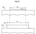
- FIG. 12 is a diagram showing the relationship between the cleaning width of the blade D 1 , and the paper width D 3 in an inkjet recording apparatus of the second exemplary embodiment of the present invention.
- FIG. 1 is shown, as the liquid ejection apparatus of the present exemplary embodiment, an inkjet recording apparatus 12 .
- a paper supply tray 16 In the lower portion of the case 14 of the inkjet recording apparatus 12 is provided a paper supply tray 16 .
- the paper P stacked inside can be fed out one sheet at a time therefrom by a pick up roll 18 .
- the fed out paper P is conveyed along a conveying path 22 configured by plural conveying roller pairs 20 .
- an endless conveying belt 28 is entrained around a driving roll 24 , and driven rolls 26 , 27 and 29 as a conveying member.
- the driving roll 24 and the driven roll 26 are arranged in a substantially horizontal plane, and below these are arranged the driven rolls 27 and 29 , again arranged in a substantially horizontal plane.
- a recording head array 30 facing a flat portion 28 F of the conveying belt 28 between the driving roll 24 and the driven roll 26 .
- This opposing region is the ejection region SE where ink droplets are ejected from the recording head array 30 .
- Paper P conveyed on the conveying path 22 is held and supported on the conveying belt 28 to reach the ejection region SE, and, in a state of opposing the recording head array 30 , ink droplets from the recording head array 30 are adhered to the paper P according to image information.
- the recording head array 30 is a rectangular shape having an effective recording region that is the width of the paper P or greater (the dimension of the paper P in the direction orthogonal to the conveying direction), and the recording head array 30 has four inkjet recording heads 32 arranged in the conveying direction as four droplet ejection heads (referred to below as recording heads).
- the corresponding colors thereof are yellow (Y), magenta (M), cyan (C), and black (K), and full color image recoding may be made therewith.
- Each of the recording heads 32 is driven by a head driving circuit (not illustrated).
- the head driving circuit for example, is configured to determine the ejection timing of ink droplets according to the image information and the ink ejection aperture (nozzle) to be used, and sends a driving signal to the recording head 32 .
- the recording head array 30 may be immovable in the direction orthogonal to the conveying direction, but by structuring to be movable as the need arises, recording of a higher resolution may be made by image recording using multi-pass, and the influence of deficiencies in the recording head 32 on the recording result may be avoided.
- Each of the recording heads 32 is arranged at the sides of the recording head array 30 .
- the recording head array 30 is moved upward, and the maintenance units 34 are moved to enter into the space between the conveying belt 28 and the recording head array 30 .
- specific maintenance operations such as suctioning, wiping, capping
- ink tanks 35 that store inks of each of the colors are disposed above the recording head array 30 .
- Each of the ink tanks 35 are connected to its respective recording head 32 .
- a charging roll 36 connected to a power source 38 is disposed as a charging unit.
- the charging roll 36 sandwiches the conveying belt 28 and the paper P between itself and the driven roll 26 , and is driven, pressing the paper P onto the conveying belt 28 .
- charge may be applied to the paper P and paper P may be electrostatically attracted onto the conveying belt 28 .
- a releasing scraper 40 that releases the paper P from the conveying belt 28 .
- the released paper P is conveyed by plural ejection roller pairs 42 configuring an discharge path 44 on the downstream side of the releasing scraper 40 , and discharged into an discharge paper tray 46 provided at the upper portion of the case 14 .
- the belt cleaning unit 48 is provided with a blade 49 as a cleaning member, and a recovery box 51 into which is recovered ink and the like that is scraped off the conveying belt 28 by the blade 49 .
- the blade 49 contacts with a portion of the conveying belt 28 that is wrapped around the driving roll 24 , and scrapes off ink and the like that is adhered to the conveying belt 28 .
- An absorbent member 53 is spread out in the bottom portion of the recovery box 51 , and absorbs liquid that drops off from the blade 49 .
- a grounded charge removal roll 62 On the downstream side of the belt cleaning unit 48 is disposed a grounded charge removal roll 62 , as a charge removal unit.
- the charge removal roll 62 sandwiches the conveying belt 28 between itself and the driven roll 27 , and is driven, removing the charge on the conveying belt 28 .
- An oil coating unit 64 and a back up plate 66 are provided between the driven roll 26 and the driven roll 27 , facing the conveying belt 28 therebetween.
- the oil coating unit 64 faces the outer peripheral surface of the conveying belt 28 , and the back up plate 66 contacts with the inner peripheral surface of the conveying belt 28 .
- the oil coating unit 64 is provided with: a case 68 ; an oil coating roll 70 , as a coating member, rotatably supported in the case 68 ; and an oil blade 72 supported by the case 68 .
- the oil coating roll 70 is pressed by the back up plate 66 through the intervening conveying belt 28 , and rotated by being driven by the conveying belt 28 .
- the oil coating roll 70 is formed of a porous body of polyethylene, urethane or the like, impregnated with silicone oil as a lubricant, and coats the conveying belt 28 with silicone oil. Therefore, the is a silicone oil film present between the conveying belt 28 and the blade 49 , and so friction is relieved between the conveying belt 28 and the blade 49 .
- the ink that is ejected from the recording heads 32 is a water based ink. Therefore, if ink adheres to the conveying belt 28 due to unnecessary ink ejection when there is a paper jam, or due to dummy jetting or the like ejecting ink onto the conveying belt 28 , then ink may be cohered by the water repellant effect of the film of silicone oil on the conveying belt 28 . Therefore, increase in the adhering force of the ink to the conveying belt 28 may be suppressed, and when cleaning the conveying belt 28 with the blade 49 , ink may be easily separated from the conveying belt 28 .
- a driving roll may be used for the oil coating roll 70 . In such a case, slipping of the oil coating roll 70 relative to the conveying belt 28 may be prevented.
- the oil blade 72 contacts the conveying belt 28 at a position that is at the downstream side of the oil coating roll 70 in the rotation direction of the conveying belt 28 , and scrapes off excess silicone oil coated onto the conveying belt 28 to give a specific thickness of silicone oil film.
- the oil blade 72 may use rubber materials such as a flurorubber, NBR or the like, thin metal plate such as SUS (stainless steel) or the like, or resin films such as polyurethane, PET or the like.
- the bottom portion of the case 68 is covered with absorbent material 74 such as sponge, and this absorbent material 74 absorbs the silicone oil scraped off from the conveying belt 28 by the oil blade 72 .
- the conveying belt 28 may be formed of resins such as PET, PI, PA and the like, or rubber materials such as CR, NBR, HNBR, urethane rubber and the like, and coating treatment may be carried out on the surface thereof.
- the blade 49 may be formed of rubber materials such as a flurorubber, NBR, HNBR or the like, thin metal plate such as SUS (stainless steel) or the like, or resin films such as polyurethane, PET or the like.
- the roll portion of the oil coating roll 70 may be appropriately formed of a non-woven fabric formed from polyester, polyamide or the like, but as long as a predetermined amount of ink is able to penetrate therein, and wrapping around is possible, then other materials may be substituted.
- a silicone oil may be used as the lubricant that is coated on the conveying belt 28 by the oil coating roll 70 (referred to below as lubricant), and a water based ink may be used.
- a lubricant that repels the ink is appropriate, and for a water based ink, as well as a silicone oil, the following may be used: higher fatty acids, such as oleic acid, linoleic acid and the like; plasticizers such as dibutylphthalate, diisodecylphthalate, dibutylmaleate and the like; non water soluble alcohols such as n-decanol, dimethylbutanol and the like; and liquids that have water repellant properties such as fluoro oils, mineral oils, vegetable oils and the like.
- a liquid with high oil repellant properties may be used, such as water.
- the dynamic viscosity of the lubricant is in the range of 10 to 10 4 mm 2 /s, and more preferably in the range of 50 to 10 2 mm 2 /s.
- the thickness of coating of the lubricant is too thick, then the oil may penetrate into the paper P and this may lead to a detrimental effect on the quality of the image, such as the paper P repelling the ink and the like.
- the thickness of the coating of the lubricant is too thin then it may not be possible to relieve the friction between the blade 49 and the conveying belt 28 , and further it may not be possible to carry out good cleaning by the blade 49 . It is, therefore, necessary to set the thickness of coating the lubricant to within an appropriate range.
- An appropriate range for the coating thickness of the lubricant is 1 nm to 20 ⁇ m.
- the lubricant is not volatile at room temperature. Specifically, the vapor pressure at 25° C. should be 13.33 Pa or less. Also, it is necessary that the lubricant is not compatible with the ink. Specifically, the solubility to ink should be 0.1 wt % or less at room temperature (25° C.).
- the surface tension of the lubricant J is designated ⁇ o
- the critical surface tension of the conveying belt 28 is designated ⁇ b .
- the critical surface tension is the surface tension, in the relationship of the solid surface contact angle ⁇ to the surface tensions of various liquids, when cos ⁇ is adjusted to 1 (that is when the contact angle of the liquid to the solid surface becomes 0°).
- solid surfaces are well wetted by liquids that have a surface tension that is smaller than the critical surface tension of the surface.
- the maximum value L 0 of the width, in the direction orthogonal to the conveying direction, of the ink droplet ejecting of the recording head 32 (referred to below as the maximum printing width)
- the width L 1 , in the direction orthogonal to the conveying direction, of the cleaning of the conveying belt 28 by the blade 49 (referred to below as the cleaning width)
- the width L 2 , in the direction orthogonal to the conveying direction, of coating the silicone oil on the conveying belt 28 by the oil coating roll 70 (referred to below as the coating width) should satisfy the formula below (1).
- the cleaning width L 1 is equivalent to the width, in the direction orthogonal to the conveying direction, of contact between the blade 49 and the conveying belt 28
- the coating width L 2 is equivalent to the width, in the direction orthogonal to the conveying direction, of contact between the oil coating roll 70 and the conveying belt 28 .
- cleaning width L 1 of the blade 49 being the same as or greater than the maximum printing width L 0 of the recording head 32 , cleaning by the blade 49 is carried out over the complete region of the silicone oil film on the conveying belt 28 to which ink droplets have adhered.
- the coating width L 2 of the oil coating roll 70 being the same as or greater than the maximum printing width L 0 of the recording head 32 , there is the silicone oil film between the conveying belt 28 and all of the ink droplets on the conveying belt 28 , and increase may be prevented in the adhering force of all of the ink droplets on the conveying belt 28 to the conveying belt 28 . Therefore, good cleaning of the conveying belt 28 may be carried out such that there are no remnants of the ink on the conveying belt 28 .
- the coating width L 2 of the oil coating roll 70 being the same as or greater than the cleaning width L 1 of the blade 49 , there is the silicone oil film between the conveying belt 28 and the blade 49 across the entire region of the direction orthogonal to the conveying direction of the conveying belt 28 , and friction may be relieved between the conveying belt 28 and the blade 49 , Therefore, damage of the conveying belt 28 and the blade 49 may be suppressed, and the reliability of the conveying belt 28 and the blade 49 can be improved, also changes in the load imparted to the conveying belt 28 by the blade 49 may be suppressed.
- the coating width L 2 and the cleaning width L 1 are longer than the maximum printing width L 0 , and the coating width L 2 is longer than the cleaning width L 1 .
- the width L 3 of the paper P in the direction orthogonal to the conveying direction (referred to below as the paper width) and the cleaning width L 1 satisfy the following formula (2).
- the cleaning width L 1 being the same as or greater than the paper width L 3 , ink mist adhered in the region of contact between the paper P and the conveying belt 28 is completely scraped off by the blade 49 , and so soiling of the paper P by ink mist adhered to the conveying belt 28 may be prevented.
- the paper width L 3 and the width of the charging roll 36 charging the conveying belt 28 in the direction orthogonal to the conveying direction are required to satisfy formula (3) below.
- the charging width L 4 of the charging roll 36 is equivalent to the width of contact of the charging roll 36 and the conveying belt 28 in the direction orthogonal to the conveying direction. L4 ⁇ L3 (3)
- the charging width L 4 of the charging roll 36 being the same or greater than the paper width L 3 , the whole width of the paper P may be electrostatically attracted onto the conveying belt 28 , and the paper P may be stably conveyed by the conveying belt 28 .
- the charging width L 4 is wider than the paper width L 3 .
- the charge on the conveying belt 28 is completely removed by the charge removal roll 62 , and so it is necessary that the charging width L 4 of the charging roll 36 and the width L 5 , in the direction orthogonal to the conveying direction, of the removal of the charge from the conveying belt 28 by the charge removal roll 62 (referred to below as the charge removal width) satisfies the formula (4) below.
- the charge removal width L 5 of the charge removal roll 62 being the same as or greater than the charging width L 4 of the charging roll 36 , charge may be removed from all of the region of the conveying belt 28 that is charged by the charging roll 36 , and various problems that are caused by charge remaining on the conveying belt 28 may be suppressed.
- the charge removal width L 5 is wider that the charging width L 4 .
- the ink jet recording apparatus 100 is a full color printer for forming a full color image on paper P with four colors of ink, yellow (Y), magenta (M), cyan (C), and black (K).
- the ink jet recording apparatus 100 is a printer using an offset method, and by ejecting ink towards an intermediate transfer drum 104 as a holding member (carrier), first forms an ink image on the intermediate transfer drum 104 , and then transfers the ink image from the intermediate transfer drum 104 to the paper P.
- a removable paper supply tray 16 At a lower portion of ink jet recording apparatus 100 is provided a removable paper supply tray 16 . Paper P is stacked in the paper supply tray 16 , and the uppermost of paper P is in contact with a pick up roll 18 . Paper P may be supplied one sheet at a time by the pick up roll 18 at the downstream side of the conveying direction, and supplied to an image forming unit 122 by pairs of conveying rolls 109 , 120 , 121 , 123 , and 125 disposed in the above order along a conveying path. The rolls of conveying rolls 123 , 125 that contact the face of paper P to which the ink image is transferred are star wheels.
- the intermediate transfer drum 104 is disposed facing the conveying path, and a recording head array 30 is disposed above the intermediate transfer drum 104 , and maintenance units 34 are also disposed in the vicinity of the recording head array 30 .
- the recording head array 30 is in the vicinity of the intermediate transfer drum 104 when ejecting ink. Also, as shown in FIG. 8 , when maintaining, the recording head array 30 is distanced from the intermediate transfer drum 104 and a space between the recording head array 30 and the intermediate transfer drum 10 for inserting the maintenance units 34 may be secured.
- the maintenance units 34 when forming an image, recede to the outside of the ejection region SE where ink droplets are ejected from the recording head array 30 . And, as shown in FIG. 8 , when not forming an image, the maintenance units 34 are introduced into the ejection region SE.
- a charging roll 128 as a transfer unit
- a charge removing roll 130 as a transfer unit
- a releasing scraper 132 contacting the intermediate transfer drum 104 at the conveying path side, are a charging roll 128 as a transfer unit, a charge removing roll 130 as a transfer unit, and a releasing scraper 132 , in that order from the upstream side in the conveying direction.
- the charging roll 128 presses the paper P against the intermediate transfer drum 104 and applies a charge to the paper P, and the paper P is attracted by electrostatic attraction to the intermediate transfer drum 104 , and an ink image is transferred to the paper P.
- the charge removing roll 130 conveys the paper P while removing the charge from the paper P, and releases the electrostatic attraction between the paper P and the intermediate transfer drum 104 .
- the releasing scraper 132 releases the paper P from the intermediate transfer drum 104 .
- conveying roll pairs 127 , 129 , 131 , 133 , 135 , 137 , and 139 are disposed downstream in the conveying direction of the releasing scraper 132 , downstream in the conveying direction of the releasing scraper 132 , in that order from the upstream side in the conveying direction.
- the conveying rolls of the conveying roll pairs 127 , 133 , 135 , 137 , and 139 that contact the face of the paper P on which the ink image has been transferred are star wheels, and contact with the face of the paper P on which the ink image has been transferred is reduced.
- the ink tanks 35 is disposed a discharge tray 46 , and at the side of the discharge tray 46 is disposed the conveying roller pair 139 .
- the paper P is ejected into the discharge tray 46 by the conveying roller pair 139 .
- a drum cleaning unit 148 is disposed further to the downstream side in the rotation direction of the intermediate transfer drum 104 than the releasing scraper 132 and further to the upstream side in the rotation direction of the intermediate transfer drum 104 than the recording head array 30 .
- This drum cleaning unit 148 is equipped with a blade 49 as a cleaning unit which contacts the peripheral surface of the intermediate transfer drum 104 , scrapes off ink and the like that has not been transferred to the paper P and remains on the intermediate transfer drum 104 ; and a recovery box 51 that recovers the ink and the like that has been scraped off from the intermediate transfer drum 104 by the blade 49 .
- An absorbent member 53 is spread out at the bottom of the recovery box 51 , and liquid that drips down from the blade 49 is absorbed thereby.
- an oil coating unit 164 is disposed downstream in the rotation direction of the intermediate transfer drum 104 of the blade 49 , and downstream in the rotation direction of the intermediate transfer drum 104 of the recording head array 30 .
- the oil coating unit 164 is provided with a case 68 and an oil coating roll 70 , as a coating unit, rotatably supported by the case 68 .
- the oil coating roll 70 is pressed by the intermediate transfer drum 104 , and rotated by being driven by the intermediate transfer drum 104 .
- the oil coating roll 70 is formed of a porous body of polyethylene, urethane or the like, impregnated with silicone oil as a lubricant, and coats the intermediate transfer drum 104 with silicone oil. Due to this there is a film of silicone oil between the intermediate transfer drum 104 and blade 49 , and friction between the intermediate transfer drum 104 and blade 49 can be relieved.
- the ink that is ejected from the recording heads 32 is a water based ink, and therefore, ink may be cohered by the water repellant effect of the film of silicone oil on the intermediate transfer drum 104 . Therefore, increase in the adhering force of the ink to the intermediate transfer drum 104 may be suppressed, and when cleaning the intermediate transfer drum 104 with the blade 49 , ink may be easily separated from the intermediate transfer drum 104 .
- a driving roll may be used for the oil coating roll 70 . In such a case slipping of the oil coating roll 70 relative to the intermediate transfer drum 104 may be prevented.
- ink I does not wet out onto the surface of the film of lubricant J, and the ink coheres and becomes easier to scrape off from the intermediate transfer drum 104 by the blade 49 .
- the friction between the intermediate transfer drum 104 and the blade 49 needs to be relieved across the whole of its width in the direction orthogonal to the conveying direction.
- the maximum value D 0 of the width, in the direction orthogonal to the conveying direction, of the ink droplet ejecting of the recording head 32 (referred to below as the maximum printing width), and the width D 1 , in the direction orthogonal to the conveying direction, of the cleaning of the intermediate transfer drum 104 by the blade 49 (referred to below as the cleaning width), and the width D 2 , in the direction orthogonal to the conveying direction, of coating the silicone oil on the intermediate transfer drum 104 by the oil coating roll 70 (referred to below as the coating width) should satisfy the formulae (5) below.
- the cleaning width D 1 is equivalent to the width, in the direction orthogonal to the conveying direction, of contact between the blade 49 and the intermediate transfer drum 104
- the coating width D 2 is equivalent to the width, in the direction orthogonal to the conveying direction, of contact between the oil coating roll 70 and the intermediate transfer drum 104 .
- cleaning width D 1 of the blade 49 being the same as or greater than the maximum printing width D 0 of the recording head 32 , cleaning is carried out by the blade 49 for all of the region in which ink droplets are adhered to the silicone oil film on the intermediate transfer drum 104 .
- the coating width D 2 of the oil coating roll 70 being the same as or greater than the maximum printing width D 0 of the recording head 32 , there is the silicone oil film between all of the ink droplets on the intermediate transfer drum 104 and the intermediate transfer drum 104 itself, and increase may be prevented in the adhering force of all of the ink droplets on the intermediate transfer drum 104 to the intermediate transfer drum 104 . Therefore, good cleaning of the intermediate transfer drum 104 may be carried out such that there are no remnants of the ink on the intermediate transfer drum 104 .
- the coating width D 2 of the oil coating roll 70 being the same as or greater than the cleaning width D 1 of the blade 49 , there is the silicone oil film between the intermediate transfer drum 104 and the blade 49 over the whole of the region in the direction orthogonal to the conveying direction, and friction between the intermediate transfer drum 104 and the blade 49 can be relieved. Therefore, occurrence of damage between the intermediate transfer drum 104 and the blade 49 can be suppressed, and the reliability of the intermediate transfer drum 104 and the blade 49 can be improved, and variations in the load on the intermediate transfer drum 104 by the blade 49 can be suppressed.
- coating width D 2 and cleaning width D 1 are made longer than the maximum printing width D 0 , and coating width D 2 is made longer than cleaning width D 1 .
- the width D 3 of the paper P in the direction orthogonal to the conveying direction (referred to below as the paper width) and the cleaning width D 1 satisfy the following formula (6).
- the cleaning width D 1 being the same as or greater than the paper width D 3 , ink mist adhered in the region of contact between the paper P and the intermediate transfer drum 104 is completely scraped off by the blade 49 , and so soiling of the paper P by ink mist adhered to the intermediate transfer drum 104 may be prevented.
- ink jet recording apparatuses have been explained as examples of the present invention, however the invention is not limited to ink jet recording apparatuses, and may be applied to various industrial applications for general droplet ejection apparatuses such as: manufacturing of color filters for display use, by ejecting coloration ink onto polymer films; forming EL display panels by carrying out ejecting of organic EL liquid solutions onto substrates, and the like.
- the “recording medium” for image recording in the droplet ejection apparatus of the invention all objects and materials on which droplets may be ejected by a droplet ejection head are included. Therefore, while the recording medium of course may be recording paper and OHP sheets and the like, it also includes other objects and materials such as, for example, polymer films.
- the “droplet ejection head” of the droplet ejection apparatus of the present invention all ejectors that eject droplets towards a recording medium or holding member are included.
- ink jet recording heads that are smaller in length than the width of the paper P and that eject ink droplets by moving in the width direction of the paper P, and the like are included.
- the “conveying member” of the droplet ejection apparatus of the present invention all members that retain and convey a recording medium are included.
- drums that retain a recording medium on the peripheral surface thereof and rotate, and reciprocating tables that retain a recording medium and, and the like are included.
- conveyers that contact a recording medium to a holding member and convey are included.
- conveying rolls that nip and convey a recording medium, and the like are included.
- the “holding member (carrier)” of the droplet ejection apparatus of the present invention all members that carry liquid ejected from a droplet ejection head are included. For example, rotating belts on which droplets are carried, and the like are included.
- cleaning members of the droplet ejection apparatus of the present invention
- all members that clean droplets adhered to conveying members are included.
- cleaning rolls that contact the conveying member and rotate absorbing the droplets, and movable blades that contact the conveying member and move in a direction that intersects with the conveying direction, and the like are included.
- cleaning unit of the droplet ejection apparatus of the present invention
- all cleaners that clean droplets adhered to the holding member are included.
- cleaning rolls that contact the holding member and rotate absorbing the droplets, and movable blades that contact the conveying member and move in a direction that intersects with the conveying direction, and the like are included.
- all members that coat onto a conveying member a lubricant are included. Included, for example, are: droplet ejection heads that eject such a lubricant towards a conveying member; webs that are impregnated with such a lubricant and contact with the conveying member; rolls that retain such a lubricant on the surface thereof, contact with the conveying member and rotate; and rolls that are impregnated with, or retain such a lubricant on the surface thereof, contact with the conveying member and move in a direction that intersects with the conveying direction.
- all devices for coating onto a holding member a lubricant are included. Included, for example, are: droplet ejection heads that eject such a lubricant towards a holding member; webs that are impregnated with such a lubricant and contact with the holding member; rolls that retain such a lubricant on the surface thereof, contact with the holding member and rotate; and rolls that are impregnated with, or retain such a lubricant on the surface thereof, contact with the holding member and move in a direction that intersects with the conveying direction.
- the “charging unit” of the droplet ejection apparatus of the present invention all devices for charging a conveying member are included.
- corotrons that carry out non-contact charging of the conveying member are included.
- charge removing unit of the droplet ejection apparatus of the present invention
- all devices for removing charge from a conveying member are included.
- charge removing lamps that remove charge from the conveying member are included.
Landscapes
- Ink Jet (AREA)
- Accessory Devices And Overall Control Thereof (AREA)
- Feeding Of Articles By Means Other Than Belts Or Rollers (AREA)
Abstract
L2≧L1 (1)
Description
L2≧L1 (1)
γo<γb (A)
γo<γi (B)
L2≧L1≧L0 (1)
L1≧L3 (2)
L4≧L3 (3)
L5≧L4 (4)
γo<γb (A)
γo<γi (B)
D2≧D1≧D0 (5)
D1≧D3 (6)
Claims (16)
L2≧L1 (1)
L1≧L3 (2).
L4≧L3 (3).
L5≧L4 (4).
D2≧D1 (5)
D1≧D3 (6).
K2≧K1 (7)
K1≧K3 (8).
K4≧K3 (9).
K5≧K4 (10).
K1≧K3 (11).
Applications Claiming Priority (2)
| Application Number | Priority Date | Filing Date | Title |
|---|---|---|---|
| JP2006-129616 | 2006-05-08 | ||
| JP2006129616A JP4752599B2 (en) | 2006-05-08 | 2006-05-08 | Droplet discharge device |
Publications (2)
| Publication Number | Publication Date |
|---|---|
| US20070257955A1 US20070257955A1 (en) | 2007-11-08 |
| US7810897B2 true US7810897B2 (en) | 2010-10-12 |
Family
ID=38660818
Family Applications (1)
| Application Number | Title | Priority Date | Filing Date |
|---|---|---|---|
| US11/704,594 Expired - Fee Related US7810897B2 (en) | 2006-05-08 | 2007-02-09 | Droplet ejection apparatus and cleaning method of a droplet receiving surface |
Country Status (2)
| Country | Link |
|---|---|
| US (1) | US7810897B2 (en) |
| JP (1) | JP4752599B2 (en) |
Cited By (1)
| Publication number | Priority date | Publication date | Assignee | Title |
|---|---|---|---|---|
| US20130222466A1 (en) * | 2012-02-24 | 2013-08-29 | Xerox Corporation | Printer Having Drum Maintenance Unit Architecture For Controlled Application of a Release Agent |
Families Citing this family (34)
| Publication number | Priority date | Publication date | Assignee | Title |
|---|---|---|---|---|
| JP4760941B2 (en) * | 2009-03-26 | 2011-08-31 | ブラザー工業株式会社 | Inkjet recording device |
| JP5544134B2 (en) * | 2009-09-29 | 2014-07-09 | セーレン株式会社 | Inkjet recording apparatus and inkjet recording method |
| WO2013132418A2 (en) | 2012-03-05 | 2013-09-12 | Landa Corporation Limited | Digital printing process |
| US11104123B2 (en) | 2012-03-05 | 2021-08-31 | Landa Corporation Ltd. | Digital printing system |
| CN104271687B (en) | 2012-03-05 | 2016-11-02 | 兰达公司 | Ink film constructs |
| US9498946B2 (en) | 2012-03-05 | 2016-11-22 | Landa Corporation Ltd. | Apparatus and method for control or monitoring of a printing system |
| US11106161B2 (en) | 2012-03-05 | 2021-08-31 | Landa Corporation Ltd. | Intermediate transfer members for use with indirect printing systems and protonatable intermediate transfer members for use with indirect printing systems |
| US9643403B2 (en) | 2012-03-05 | 2017-05-09 | Landa Corporation Ltd. | Printing system |
| CN109177531B (en) | 2012-03-15 | 2020-11-27 | 兰达公司 | Endless flexible belt for printing system |
| JP6094097B2 (en) * | 2012-08-31 | 2017-03-15 | セイコーエプソン株式会社 | Belt cleaning apparatus, medium feeding apparatus, and ink jet recording apparatus |
| JP6065686B2 (en) | 2013-03-22 | 2017-01-25 | セイコーエプソン株式会社 | RECORDED MEDIUM CONVEYING DEVICE, RECORDING DEVICE |
| GB201401173D0 (en) | 2013-09-11 | 2014-03-12 | Landa Corp Ltd | Ink formulations and film constructions thereof |
| GB2536489B (en) | 2015-03-20 | 2018-08-29 | Landa Corporation Ltd | Indirect printing system |
| GB2537813A (en) | 2015-04-14 | 2016-11-02 | Landa Corp Ltd | Apparatus for threading an intermediate transfer member of a printing system |
| JP6597226B2 (en) * | 2015-11-26 | 2019-10-30 | セイコーエプソン株式会社 | Printing device |
| DE112017002714T5 (en) | 2016-05-30 | 2019-02-28 | Landa Corporation Ltd. | Digital printing process |
| CN114148098B (en) * | 2016-05-30 | 2025-03-07 | 兰达公司 | Digital printing methods |
| CN112428691B (en) | 2016-05-30 | 2022-09-27 | 兰达公司 | Digital printing method and system |
| GB201609463D0 (en) | 2016-05-30 | 2016-07-13 | Landa Labs 2012 Ltd | Method of manufacturing a multi-layer article |
| WO2019077489A1 (en) | 2017-10-19 | 2019-04-25 | Landa Corporation Ltd. | Endless flexible belt for a printing system |
| JP7225230B2 (en) | 2017-11-19 | 2023-02-20 | ランダ コーポレイション リミテッド | digital printing system |
| WO2019102297A1 (en) | 2017-11-27 | 2019-05-31 | Landa Corporation Ltd. | Digital printing system |
| US11707943B2 (en) | 2017-12-06 | 2023-07-25 | Landa Corporation Ltd. | Method and apparatus for digital printing |
| US11679615B2 (en) | 2017-12-07 | 2023-06-20 | Landa Corporation Ltd. | Digital printing process and method |
| WO2020003088A1 (en) | 2018-06-26 | 2020-01-02 | Landa Corporation Ltd. | An intermediate transfer member for a digital printing system |
| US10994528B1 (en) | 2018-08-02 | 2021-05-04 | Landa Corporation Ltd. | Digital printing system with flexible intermediate transfer member |
| US12001902B2 (en) | 2018-08-13 | 2024-06-04 | Landa Corporation Ltd. | Correcting distortions in digital printing by implanting dummy pixels in a digital image |
| JP7246496B2 (en) | 2018-10-08 | 2023-03-27 | ランダ コーポレイション リミテッド | Friction reduction means for printing systems and methods |
| WO2020136517A1 (en) | 2018-12-24 | 2020-07-02 | Landa Corporation Ltd. | A digital printing system |
| EP3946953A4 (en) | 2019-03-31 | 2022-12-14 | Landa Corporation Ltd. | SYSTEMS AND METHODS TO PREVENT OR MINIMIZE PRINT DEFECTS IN PRINTING PROCESSES |
| CN114746813A (en) | 2019-11-25 | 2022-07-12 | 兰达公司 | Drying inks using infrared radiation in digital printing |
| US11321028B2 (en) | 2019-12-11 | 2022-05-03 | Landa Corporation Ltd. | Correcting registration errors in digital printing |
| EP4081866A4 (en) | 2019-12-29 | 2024-01-03 | Landa Corporation Ltd. | Printing method and system |
| EP4264377A4 (en) | 2021-02-02 | 2024-11-13 | Landa Corporation Ltd. | REDUCING DISTORTIONS IN PRINTED IMAGES |
Citations (3)
| Publication number | Priority date | Publication date | Assignee | Title |
|---|---|---|---|---|
| US6447113B1 (en) * | 1998-12-16 | 2002-09-10 | Silverbrook Research Pty Ltd | Duplex inkjet printing system |
| JP2004196505A (en) | 2002-12-19 | 2004-07-15 | Canon Inc | Inkjet recording device |
| US7486914B2 (en) * | 2005-05-30 | 2009-02-03 | Ricoh Company, Ltd. | Electrophotographic image forming apparatus, process cartridge and image forming method wherein lubricant is supplied to a surface of an image bearing member |
Family Cites Families (4)
| Publication number | Priority date | Publication date | Assignee | Title |
|---|---|---|---|---|
| JP2873879B2 (en) * | 1990-11-28 | 1999-03-24 | キヤノン株式会社 | Ink jet recording device |
| JPH1135185A (en) * | 1997-07-14 | 1999-02-09 | Ricoh Co Ltd | Transfer transfer device |
| JP4010009B2 (en) * | 2004-03-25 | 2007-11-21 | 富士フイルム株式会社 | Image recording apparatus and maintenance method |
| JP4460374B2 (en) * | 2004-07-13 | 2010-05-12 | 株式会社リコー | Electrostatic transfer device and image forming apparatus |
-
2006
- 2006-05-08 JP JP2006129616A patent/JP4752599B2/en not_active Expired - Fee Related
-
2007
- 2007-02-09 US US11/704,594 patent/US7810897B2/en not_active Expired - Fee Related
Patent Citations (3)
| Publication number | Priority date | Publication date | Assignee | Title |
|---|---|---|---|---|
| US6447113B1 (en) * | 1998-12-16 | 2002-09-10 | Silverbrook Research Pty Ltd | Duplex inkjet printing system |
| JP2004196505A (en) | 2002-12-19 | 2004-07-15 | Canon Inc | Inkjet recording device |
| US7486914B2 (en) * | 2005-05-30 | 2009-02-03 | Ricoh Company, Ltd. | Electrophotographic image forming apparatus, process cartridge and image forming method wherein lubricant is supplied to a surface of an image bearing member |
Cited By (2)
| Publication number | Priority date | Publication date | Assignee | Title |
|---|---|---|---|---|
| US20130222466A1 (en) * | 2012-02-24 | 2013-08-29 | Xerox Corporation | Printer Having Drum Maintenance Unit Architecture For Controlled Application of a Release Agent |
| US8662658B2 (en) * | 2012-02-24 | 2014-03-04 | Xerox Corporation | Printer having drum maintenance unit architecture for controlled application of a release agent |
Also Published As
| Publication number | Publication date |
|---|---|
| JP4752599B2 (en) | 2011-08-17 |
| JP2007301738A (en) | 2007-11-22 |
| US20070257955A1 (en) | 2007-11-08 |
Similar Documents
| Publication | Publication Date | Title |
|---|---|---|
| US7810897B2 (en) | Droplet ejection apparatus and cleaning method of a droplet receiving surface | |
| US8109595B2 (en) | Droplet ejection apparatus and cleaning method of a droplet receiving surface | |
| JP4535000B2 (en) | Droplet discharge device, method for preventing droplet adhesion on recording medium transport roller, and method for cleaning recording medium transport roller | |
| CN100572086C (en) | droplet discharge device | |
| JP4696930B2 (en) | Droplet discharge device | |
| JP4715631B2 (en) | Droplet discharge device | |
| JP4702250B2 (en) | Droplet discharge device | |
| JP2006256840A (en) | Droplet ejection device | |
| JP2004161454A (en) | Inkjet recording device | |
| JP2008055837A (en) | Droplet ejection apparatus | |
| JP2008179094A (en) | Liquid droplet discharge device | |
| JP2008044721A (en) | Droplet discharge device | |
| JP4775124B2 (en) | Droplet discharge device | |
| JP4696944B2 (en) | Droplet discharge device | |
| JP2004130719A (en) | Inkjet recording device | |
| JP2004130720A (en) | Inkjet recording device | |
| JP4449914B2 (en) | Droplet discharge device | |
| JP2006305989A (en) | Liquid droplet discharge apparatus and method for cleaning liquid droplet discharge head | |
| JP2006082286A (en) | Recording head for inkjet, and inkjet recorder | |
| JP5029052B2 (en) | Droplet discharge device | |
| JP2004130721A (en) | Inkjet recording device | |
| JP2010188556A (en) | Image forming apparatus | |
| JP2008023777A (en) | Liquid droplet discharge apparatus | |
| JP2008213351A (en) | Droplet discharge apparatus and image forming apparatus | |
| JP2006256046A (en) | Recording medium transfer member and droplet discharge device |
Legal Events
| Date | Code | Title | Description |
|---|---|---|---|
| AS | Assignment |
Owner name: FUJI XEROX CO., LTD., JAPAN Free format text: ASSIGNMENT OF ASSIGNORS INTEREST;ASSIGNORS:TANAKA, ARICHIKA;SATOH, HIROAKI;SEKIMOTO, MASAHIKO;AND OTHERS;REEL/FRAME:018986/0802 Effective date: 20070205 |
|
| FEPP | Fee payment procedure |
Free format text: PAYOR NUMBER ASSIGNED (ORIGINAL EVENT CODE: ASPN); ENTITY STATUS OF PATENT OWNER: LARGE ENTITY |
|
| FPAY | Fee payment |
Year of fee payment: 4 |
|
| FEPP | Fee payment procedure |
Free format text: MAINTENANCE FEE REMINDER MAILED (ORIGINAL EVENT CODE: REM.) |
|
| LAPS | Lapse for failure to pay maintenance fees |
Free format text: PATENT EXPIRED FOR FAILURE TO PAY MAINTENANCE FEES (ORIGINAL EVENT CODE: EXP.); ENTITY STATUS OF PATENT OWNER: LARGE ENTITY |
|
| STCH | Information on status: patent discontinuation |
Free format text: PATENT EXPIRED DUE TO NONPAYMENT OF MAINTENANCE FEES UNDER 37 CFR 1.362 |
|
| FP | Lapsed due to failure to pay maintenance fee |
Effective date: 20181012 |