US7808949B2 - Method for scheduling distributed virtual resource blocks - Google Patents
Method for scheduling distributed virtual resource blocks Download PDFInfo
- Publication number
- US7808949B2 US7808949B2 US12/349,470 US34947009A US7808949B2 US 7808949 B2 US7808949 B2 US 7808949B2 US 34947009 A US34947009 A US 34947009A US 7808949 B2 US7808949 B2 US 7808949B2
- Authority
- US
- United States
- Prior art keywords
- dvrb
- resource blocks
- rbg
- block interleaver
- virtual resource
- Prior art date
- Legal status (The legal status is an assumption and is not a legal conclusion. Google has not performed a legal analysis and makes no representation as to the accuracy of the status listed.)
- Active
Links
Images


Classifications
-
- H—ELECTRICITY
- H04—ELECTRIC COMMUNICATION TECHNIQUE
- H04B—TRANSMISSION
- H04B7/00—Radio transmission systems, i.e. using radiation field
- H04B7/02—Diversity systems; Multi-antenna system, i.e. transmission or reception using multiple antennas
- H04B7/12—Frequency diversity
-
- H—ELECTRICITY
- H04—ELECTRIC COMMUNICATION TECHNIQUE
- H04W—WIRELESS COMMUNICATION NETWORKS
- H04W72/00—Local resource management
- H04W72/04—Wireless resource allocation
- H04W72/044—Wireless resource allocation based on the type of the allocated resource
- H04W72/0446—Resources in time domain, e.g. slots or frames
-
- H—ELECTRICITY
- H04—ELECTRIC COMMUNICATION TECHNIQUE
- H04L—TRANSMISSION OF DIGITAL INFORMATION, e.g. TELEGRAPHIC COMMUNICATION
- H04L1/00—Arrangements for detecting or preventing errors in the information received
- H04L1/004—Arrangements for detecting or preventing errors in the information received by using forward error control
- H04L1/0056—Systems characterized by the type of code used
- H04L1/0071—Use of interleaving
-
- H—ELECTRICITY
- H04—ELECTRIC COMMUNICATION TECHNIQUE
- H04L—TRANSMISSION OF DIGITAL INFORMATION, e.g. TELEGRAPHIC COMMUNICATION
- H04L5/00—Arrangements affording multiple use of the transmission path
- H04L5/0001—Arrangements for dividing the transmission path
- H04L5/0003—Two-dimensional division
- H04L5/0005—Time-frequency
- H04L5/0007—Time-frequency the frequencies being orthogonal, e.g. OFDM(A), DMT
-
- H—ELECTRICITY
- H04—ELECTRIC COMMUNICATION TECHNIQUE
- H04L—TRANSMISSION OF DIGITAL INFORMATION, e.g. TELEGRAPHIC COMMUNICATION
- H04L5/00—Arrangements affording multiple use of the transmission path
- H04L5/0001—Arrangements for dividing the transmission path
- H04L5/0028—Variable division
-
- H—ELECTRICITY
- H04—ELECTRIC COMMUNICATION TECHNIQUE
- H04L—TRANSMISSION OF DIGITAL INFORMATION, e.g. TELEGRAPHIC COMMUNICATION
- H04L5/00—Arrangements affording multiple use of the transmission path
- H04L5/003—Arrangements for allocating sub-channels of the transmission path
- H04L5/0037—Inter-user or inter-terminal allocation
- H04L5/0039—Frequency-contiguous, i.e. with no allocation of frequencies for one user or terminal between the frequencies allocated to another
-
- H—ELECTRICITY
- H04—ELECTRIC COMMUNICATION TECHNIQUE
- H04L—TRANSMISSION OF DIGITAL INFORMATION, e.g. TELEGRAPHIC COMMUNICATION
- H04L5/00—Arrangements affording multiple use of the transmission path
- H04L5/003—Arrangements for allocating sub-channels of the transmission path
- H04L5/0037—Inter-user or inter-terminal allocation
- H04L5/0041—Frequency-non-contiguous
-
- H—ELECTRICITY
- H04—ELECTRIC COMMUNICATION TECHNIQUE
- H04L—TRANSMISSION OF DIGITAL INFORMATION, e.g. TELEGRAPHIC COMMUNICATION
- H04L5/00—Arrangements affording multiple use of the transmission path
- H04L5/003—Arrangements for allocating sub-channels of the transmission path
- H04L5/0044—Arrangements for allocating sub-channels of the transmission path allocation of payload
-
- H—ELECTRICITY
- H04—ELECTRIC COMMUNICATION TECHNIQUE
- H04L—TRANSMISSION OF DIGITAL INFORMATION, e.g. TELEGRAPHIC COMMUNICATION
- H04L5/00—Arrangements affording multiple use of the transmission path
- H04L5/003—Arrangements for allocating sub-channels of the transmission path
- H04L5/0078—Timing of allocation
- H04L5/0085—Timing of allocation when channel conditions change
-
- H—ELECTRICITY
- H04—ELECTRIC COMMUNICATION TECHNIQUE
- H04L—TRANSMISSION OF DIGITAL INFORMATION, e.g. TELEGRAPHIC COMMUNICATION
- H04L5/00—Arrangements affording multiple use of the transmission path
- H04L5/0091—Signaling for the administration of the divided path
- H04L5/0092—Indication of how the channel is divided
-
- H—ELECTRICITY
- H04—ELECTRIC COMMUNICATION TECHNIQUE
- H04L—TRANSMISSION OF DIGITAL INFORMATION, e.g. TELEGRAPHIC COMMUNICATION
- H04L5/00—Arrangements affording multiple use of the transmission path
- H04L5/003—Arrangements for allocating sub-channels of the transmission path
- H04L5/0058—Allocation criteria
- H04L5/006—Quality of the received signal, e.g. BER, SNR, water filling
-
- H—ELECTRICITY
- H04—ELECTRIC COMMUNICATION TECHNIQUE
- H04L—TRANSMISSION OF DIGITAL INFORMATION, e.g. TELEGRAPHIC COMMUNICATION
- H04L5/00—Arrangements affording multiple use of the transmission path
- H04L5/003—Arrangements for allocating sub-channels of the transmission path
- H04L5/0058—Allocation criteria
- H04L5/0064—Rate requirement of the data, e.g. scalable bandwidth, data priority
-
- H—ELECTRICITY
- H04—ELECTRIC COMMUNICATION TECHNIQUE
- H04W—WIRELESS COMMUNICATION NETWORKS
- H04W88/00—Devices specially adapted for wireless communication networks, e.g. terminals, base stations or access point devices
- H04W88/08—Access point devices
Definitions
- the present invention relates to a broadband wireless mobile communication system, and more particularly, to radio resource scheduling for uplink/downlink packet data transmission in a cellular OFDM wireless packet communication system.
- uplink/downlink data packet transmission is made on a subframe basis and one subframe is defined by a certain time interval including a plurality of OFDM symbols.
- OFDM orthogonal frequency division multiplex
- the Third Generation Partnership Project (3GPP) supports a type 1 radio frame structure applicable to frequency division duplex (FDD), and a type 2 radio frame structure applicable to time division duplex (TDD).
- the structure of a type 1 radio frame is shown in FIG. 1 .
- the type 1 radio frame includes ten subframes, each of which consists of two slots.
- the structure of a type 2 radio frame is shown in FIG. 2 .
- the type 2 radio frame includes two half-frames, each of which is made up of five subframes, a downlink piloting time slot (DwPTS), a gap period (GP), and an uplink piloting time slot (UpPTS), in which one subframe consists of two slots. That is, one subframe is composed of two slots irrespective of the radio frame type.
- DwPTS downlink piloting time slot
- GP gap period
- UpPTS uplink piloting time slot
- a signal transmitted in each slot can be described by a resource grid including N RB DL N SC RB subcarriers and N symb DL OFDM symbols.
- N RB DL represents the number of resource blocks (RBs) in a downlink
- N SC RB represents the number of subcarriers constituting one RB
- N symb DL represents the number of OFDM symbols in one downlink slot.
- the structure of this resource grid is shown in FIG. 3 .
- RBs are used to describe a mapping relationship between certain physical channels and resource elements.
- the RBs can be classified into physical resource blocks (PRBs) and virtual resource blocks (VRBs), which means that a RB may be either one of a PRB or a VRB.
- PRBs physical resource blocks
- VRBs virtual resource blocks
- a mapping relationship between the VRBs and the PRBs can be described on a subframe basis. In more detail, it can be described in units of each of slots constituting one subframe. Also, the mapping relationship between the VRBs and the PRBs can be described using a mapping relationship between indexes of the VRBs and indexes of PRBs. A detailed description of this will be further given in embodiments of the present invention.
- a PRB is defined by N symb DL consecutive OFDM symbols in a time domain and N SC RB consecutive subcarriers in a frequency domain.
- One PRB is therefore composed of N symb DL N SC RB resource elements.
- the PRBs are assigned numbers from 0 to N RB DL ⁇ 1 in the frequency domain.
- a VRB can have the same size as that of the PRB.
- a pair of VRBs have a single VRB index in common (may hereinafter be referred to as a ‘VRB number’) and are allocated over two slots of one subframe.
- N RB DL VRBs belonging to a first one of two slots constituting one subframe are each assigned any one index of 0 to N RB DL ⁇ 1
- N RB DL VRBs belonging to a second one of the two slots are likewise each assigned any one index of 0 to N RB DL ⁇ 1.
- VRBs Some of the plurality of aforementioned VRBs are allocated as the localized type and the others are allocated as the distributed type.
- the VRBs allocated as the localized type will be referred to as ‘localized virtual resource blocks (LVRBs)’ and the VRBs allocated as the distributed type will be referred to as ‘distributed virtual resource blocks (DVRBs)’.
- LVRBs localized virtual resource blocks
- DVRBs distributed virtual resource blocks
- the localized VRBs are directly mapped to PRBs and the indexes of the LVRBs correspond to the indexes of the PRBs.
- LVRBs of index i correspond to PRBs of index i. That is, an LVRB 1 having the index i corresponds to a PRB 1 having the index i, and an LVRB 2 having the index i corresponds to a PRB 2 having the index i (see FIG. 5 ). In this case, it is assumed that the VRBs of FIG. 5 are all allocated as LVRBs.
- the distributed VRBs may not be directly mapped to PRBs. That is, the indexes of the DVRBs can be mapped to the PRBs after being subjected to a series of processes.
- the order of a sequence of consecutive indexes of the DVRBs can be interleaved by a block interleaver.
- the sequence of consecutive indexes means that the index number is sequentially incremented by one beginning with 0.
- a sequence of indexes outputted from the interleaver is sequentially mapped to a sequence of consecutive indexes of PRB 1 s (see FIG. 6 ). It is assumed that the VRBs of FIG. 6 are all allocated as DVRBs.
- the sequence of indexes outputted from the interleaver is cyclically shifted by a predetermined number and the cyclically shifted index sequence is sequentially mapped to a sequence of consecutive indexes of PRB 2 s (see FIG. 7 ). It is assumed that the VRBs of FIG. 7 are all allocated as DVRBs. In this manner, PRB indexes and DVRB indexes can be mapped over two slots.
- a sequence of consecutive indexes of the DVRBs may be sequentially mapped to the sequence of consecutive indexes of the PRB 1 s without passing through the interleaver. Also, the sequence of consecutive indexes of the DVRBs may be cyclically shifted by the predetermined number without passing through the interleaver and the cyclically shifted index sequence may be sequentially mapped to the sequence of consecutive indexes of the PRB 2 s.
- a PRB 1 ( i ) and a PRB 2 ( i ) having the same index i can be mapped to a DVRB 1 ( m ) and a DVRB 2 ( n ) having different indexes m and n.
- a PRB 1 ( 1 ) and a PRB 2 ( 1 ) are mapped to a DVRB 1 ( 6 ) and a DVRB 2 ( 9 ) having different indexes.
- a frequency diversity effect can be obtained based on the DVRB mapping scheme.
- VRB( 1 )s among the VRBs, are allocated as DVRBs as in FIG. 8
- LVRBs cannot be assigned to a PRB 2 ( 6 ) and a PRB 1 ( 9 ) although VRBs have not been assigned yet to the PRB 2 ( 6 ) and PRB 1 ( 9 ).
- radio resources can be allocated to each terminal with a LVRB and/or DVRB scheme.
- the information indicating which scheme is used can be transmitted with a bitmap format.
- the allocation of radio resources to each terminal can be carried out in units of one RB.
- resources can be allocated with a granularity of ‘1’ RB, but a large amount of bit overhead is required to transmit the allocation information with the bitmap format.
- the RB allocation is not sophisticatedly performed, but there is an advantage that bit overhead is reduced.
- LVRBs can be mapped to PRBs on an RBG basis.
- PRBs having three consecutive indexes a PRB 1 ( i ), PRB 1 ( i+ 1), PRB 1 ( i+ 2), PRB 2 ( i ), PRB 2 ( i+ 1) and PRB 2 ( i+ 2), may constitute one RBG, and LVRBs may be mapped to this RBG in units of an RBG.
- the DVRB mapping rules may affect the LVRB mapping, there is a need to determine the DVRB mapping rules in consideration of the LVRB mapping.
- An object of the present invention devised to solve the problem lies on a resource scheduling method for efficiently combining scheduling of an FSS scheme and scheduling of an FDS scheme.
- the object of the present invention can be achieved by providing, in a wireless mobile communication system that supports a resource allocation scheme in which one resource block group (RBG) including consecutive physical resource blocks is indicated by one bit, a resource block mapping method for distributively mapping consecutively allocated virtual resource blocks to the physical resource blocks, the method including: interleaving, using a block interleaver, indexes of the virtual resource blocks determined from a resource indication value (RIV) indicating a start index number of the virtual resource blocks and a length of the virtual resource blocks; and sequentially mapping the interleaved indexes to indexes of the physical resource blocks on a first slot of one subframe, the subframe including the first slot and a second slot, and sequentially mapping indexes obtained by cyclically shifting the interleaved indexes by a gap for the distribution to the indexes of the physical resource blocks on the second slot, wherein the gap is a multiple of a square of the number (M RBG ) of the consecutive physical resource blocks constituting the RBG.
- N interleaver ⁇ N DVRB /( C ⁇ M RBG ) ⁇ C ⁇ M RBG [Expression (1)]
- N DVRB is the number of the distributively allocated virtual resource blocks.
- N interleaver ⁇ N DVRB /( C ⁇ M RBG ) ⁇ C ⁇ M RBG [Expression (2)]
- M RBG is the number of the consecutive physical resource blocks constituting the RBG
- N DVRB is the number of the distributively allocated virtual resource blocks.
- a degree of the block interleaver may be equal to a diversity order (N DivOrder ) determined by the distribution.
- an index P 1,d of corresponding one of the physical resource blocks on the first slot mapped to the index d may be given as in expression (3) and an index P 2,d of corresponding one of the physical resource blocks on the second slot mapped to the index d may be given as in expression (4).
- R is the number of rows of the block interleaver
- C is the number of columns of the block interleaver
- N DVRB is the number of resource blocks used for the distributively allocated virtual resource blocks
- N null is the number of nulls filled in the block interleaver
- mod means a modulo operation.
- C may be equal to the degree of the block interleaver.
- the index P 1,d may be p 1,d +N PRB ⁇ N DVRB when it is larger than N DVRB /2
- the index P 2,d may be p 2,d +N PRB ⁇ N DVRB when it is larger than N DVRB /2.
- N PRB is the number of physical resource blocks in the system.
- the step of interleaving may include dividing the interleaver into groups of the number (N D ) of physical resource blocks to which one virtual resource block is mapped and uniformly distributing nulls to the divided groups.
- the groups may correspond to rows of the block interleaver, respectively, when a degree of the block interleaver is the number of the rows of the block interleaver, and to columns of the block interleaver, respectively, when the degree of the block interleaver is the number of the columns of the block interleaver.
- a resource block mapping method for distributively mapping consecutively allocated virtual resource blocks to the physical resource blocks, the method including: interleaving, using a block interleaver, indexes of the virtual resource blocks determined from a resource indication value (RIV) indicating a start index number of the virtual resource blocks and a length of the virtual resource blocks; and sequentially mapping the interleaved indexes to indexes of the physical resource blocks on a first slot of one subframe, the subframe including the first slot and a second slot, and sequentially mapping indexes obtained by cyclically shifting the interleaved indexes by a gap for the distribution to the indexes of the physical resource blocks on the second slot, wherein the gap (N gap ) for the distribution is given as in expression (5).
- N gap round( N PRB /(2 ⁇ M RBG
- M RBG is the number of the consecutive physical resource blocks constituting the RBG
- N PRB is the number of physical resource blocks in the system.
- N DVRB min( N PRB ⁇ N gap ,N gap ) ⁇ 2 [Expression (6)]
- an index P 1,d of corresponding one of the physical resource blocks on the first slot mapped to the index d may be p 1,d +N PRB ⁇ N DVRB when it is larger than N DVRB /2
- an index P 2,d of corresponding one of the physical resource blocks on the second slot mapped to the index d may be p 2,d +N PRB ⁇ N DVRB when it is larger than N DVRB /2
- N DVRB is the number of resource blocks used for the distributively allocated virtual resource blocks.
- a resource block mapping method for distributively mapping consecutively allocated virtual resource blocks to the physical resource blocks, the method including: detecting a resource indication value (RIV) indicating a start index number of the virtual resource blocks and a length of the virtual resource blocks and determining indexes of the virtual resource blocks from the detected resource indication value; and interleaving the determined indexes of the virtual resource blocks using a block interleaver and distributively mapping the virtual resource blocks to the physical resource blocks, wherein a degree of the block interleaver is equal to a diversity order (N DivOrder ) determined by the distribution.
- RMG resource block group
- N DivOrder a diversity order
- a resource block mapping method for distributively mapping consecutively allocated virtual resource blocks to the physical resource blocks, the method including: determining indexes of the virtual resource blocks from a resource indication value (RIV) indicating a start index number of the virtual resource blocks and a length of the virtual resource blocks; and interleaving the determined indexes of the virtual resource blocks using a block interleaver and distributively mapping the virtual resource blocks to the physical resource blocks, wherein, when the number (N DVRB ) of the virtual resource blocks is not a multiple of a degree of the block interleaver, the step of mapping includes dividing the interleaver into groups of the number (N D ) of physical resource blocks to which one virtual resource block is mapped and uniformly distributing nulls to the divided groups.
- RMV resource indication value
- the groups may correspond to rows of the block interleaver, respectively, when a degree of the block interleaver is the number of the rows of the block interleaver, and to columns of the block interleaver, respectively, when the degree of the block interleaver is the number of the columns of the block interleaver.
- the control information may be a DCI transmitted over a PDCCH.
- the gap may be a function of a system bandwidth.
- an interleaved index d p1 mapped to the index p may be given as in expression (7) or expression (8), and a cyclically shifted index d p2 mapped to the index p may be given as in expression (9) or expression (10).
- R is the number of rows of the block interleaver
- C is the number of columns of the block interleaver
- N DVRB is the number of resource blocks used for the distributively allocated virtual resource blocks
- mod means a modulo operation.
- d p 1 mod ( p ′ , R ) ⁇ C + ⁇ p ′ / R ⁇ ⁇ ⁇
- the diversity order (N DivOrder ) may be a multiple of the number (N D ) of physical resource blocks to which one virtual resource block is mapped.
- the gap may be 0 when the number of the virtual resource blocks is larger than or equal to a predetermined threshold value (M th ).
- the resource block mapping method may further include receiving information about the gap, the gap being determined by the received gap information.
- a resource block mapping method for distributively mapping consecutively allocated virtual resource blocks to physical resource blocks, the method including: receiving control information including resource block allocation information indicating distributed allocation of the virtual resource blocks, and indexes of the virtual resource blocks; and interleaving the indexes of the virtual resource blocks using a block interleaver, wherein the step of interleaving includes, until the indexes of the virtual resource blocks are mapped to all indexes of physical resource blocks belonging to any one of a plurality of RBG subsets, preventing the indexes of the virtual resource blocks from being mapped to indexes of physical resource blocks belonging to a different one of the RBG subsets.
- the resource block mapping method may further include sequentially mapping the interleaved indexes to indexes of the physical resource blocks on a first slot of one subframe, the subframe including the first slot and a second slot, and sequentially mapping indexes obtained by cyclically shifting the interleaved indexes by a gap for the distribution to the indexes of the physical resource blocks on the second slot, wherein the gap for the distribution is determined such that the virtual resource blocks mapped on the first slot and the virtual resource blocks mapped on the second slot are included in the same subset.
- the number (N DVRB ) of the virtual resource blocks may be a multiple of a diversity order (N DivOrder ) determined by the distribution.
- the number (N DVRB ) of the virtual resource blocks may be a multiple of the number M RBG of the consecutive physical resource blocks constituting the RBG.
- the number (N DVRB ) of the virtual resource blocks may be a multiple of a value obtained by multiplying the number M RBG of the consecutive physical resource blocks constituting the RBG by the number (N D ) of physical resource blocks to which one virtual resource block is mapped.
- the number (N DVRB ) of the virtual resource blocks may be a multiple of a value obtained by multiplying the square (M RBG 2 ) of the number of the consecutive physical resource blocks constituting the RBG by the number (N D ) of physical resource blocks to which one virtual resource block is mapped.
- the number N DVRB of the virtual resource blocks may be a common multiple of a value obtained by multiplying the number (M RBG ) of the consecutive physical resource blocks constituting the RBG by the number (N D ) of physical resource blocks to which one virtual resource block is mapped and a degree (D) of the block interleaver.
- the degree (D) of the block interleaver may be a multiple of the number (N D ) of physical resource blocks to which one virtual resource block is mapped.
- the number N DVRB of the virtual resource blocks may be a common multiple of a value obtained by multiplying a square (M RBG 2 ) of the number of the consecutive physical resource blocks constituting the RBG by the number (N D ) of physical resource blocks to which one virtual resource block is mapped and a degree (D) of the block interleaver.
- the degree (D) of the block interleaver may be a multiple of the number (N D ) of physical resource blocks to which one virtual resource block is mapped.
- the number N DVRB of the virtual resource blocks may be a common multiple of a value obtained by multiplying a degree (D) of the block interleaver by a square (M RBG 2 ) of the number of the consecutive physical resource blocks constituting the RBG and a value obtained by multiplying the number (N D ) of physical resource blocks to which one virtual resource block is mapped by the square (M RBG 2 ) of the number of the consecutive physical resource blocks constituting the RBG.
- the degree (D) of the block interleaver may be a multiple of the number (N D ) of physical resource blocks to which one virtual resource block is mapped.
- the resource block mapping method may further include receiving the resource indication value (RIV) from the mobile station of the wireless mobile communication system, prior to the step of interleaving or the step of determining the indexes of the virtual resource blocks.
- RIV resource indication value
- FIG. 1 is a view showing an example of a radio frame structure applicable to FDD.
- FIG. 2 is a view showing an example of a radio frame structure applicable to TDD.
- FIG. 3 is a view showing an example of a resource grid structure constituting a 3GPP transmission slot.
- FIG. 4 a is a view showing an example of the structure of VRBs in one subframe.
- FIG. 4 b is a view showing an example of the structure of PRBs in one subframe.
- FIG. 5 is a view illustrating an example of a method for mapping LVRBs to PRBs.
- FIG. 6 is a view illustrating an example of a method for mapping DVRBs in a first slot to PRBs.
- FIG. 7 is a view illustrating an example of a method for mapping DVRBs in a second slot to PRBs.
- FIG. 8 is a view illustrating an example of a method for mapping DVRBs to PRBs.
- FIG. 9 is a view illustrating an example of a method for mapping DVRBs and LVRBs to PRBs.
- FIG. 10 is a view illustrating an example of a method for allocating resource blocks by a compact scheme.
- FIG. 11 is a view illustrating an example of a method for mapping two DVRBs having consecutive indexes to a plurality of contiguous PRBs.
- FIG. 12 is a view illustrating an example of a method for mapping two DVRBs having consecutive indexes to a plurality of spaced PRBs.
- FIG. 13 is a view illustrating an example of a method for mapping four DVRBs having consecutive indexes to a plurality of spaced PRBs.
- FIG. 15 is a view illustrating a bitmap configuration.
- FIG. 16 is a view illustrating an example of a method for mapping based on a combination of a bitmap scheme and a compact scheme.
- FIGS. 17 and 18 are views illustrating a DVRB mapping method according to one embodiment of the present invention.
- FIG. 19 is a view illustrating an example of a method for interleaving DVRB indexes.
- FIGS. 20 a and 20 b are views illustrating an operation of a general interleaver when the number of resource blocks used in an interleaving operation is not a multiple of a diversity order.
- FIGS. 21 a and 21 b are views illustrating a method for inserting nulls when the number of resource blocks used in an interleaving operation is not a multiple of a diversity order, in accordance with one embodiment of the present invention.
- FIG. 23 is a view illustrating an example of a method for mapping DVRB indexes, using different gaps for different terminals.
- FIG. 24 is a view for explaining the relation between DVRB and PRB indexes.
- FIG. 25 a is a view for explaining the relation between DVRB and PRB indexes.
- FIG. 25 b is a view illustrating a general method for inserting nulls in an interleaver.
- FIGS. 25 c and 25 d are views illustrating examples of a method for inserting nulls in an interleaver in one embodiment of the present invention, respectively.
- FIGS. 26 and 27 are views illustrating examples of a method using a combination of the bitmap scheme using the RBG scheme and subset scheme and the compact scheme, respectively.
- FIG. 28 is a view illustrating the case in which the number of DVRBs is set to a multiple of the number of physical resource blocks (PRBs), to which one virtual resource block (VRB) is mapped, N D , and the number of consecutive physical resource blocks constituting an RBG, M RBG , in accordance with one embodiment of the present invention.
- PRBs physical resource blocks
- VRB virtual resource block
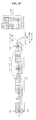
- FIG. 29 is a view illustrating the case in which DVRB indexes are interleaved in accordance with the method of FIG. 28 .
- FIG. 30 is a view illustrating an example wherein mapping is performed under the condition in which the degree of a block interleaver is set to the number of columns of the block interleaver, namely, C, and C is set to a diversity order, in accordance with one embodiment of the present invention.
- FIG. 31 is a view illustrating an example of a mapping method according to one embodiment of the present invention when the number of PRBs and the number of DVRBs are different from each other.
- FIGS. 32 and 33 are views illustrating examples of a mapping method capable of increasing the number of DVRBs, using a given gap, in accordance with one embodiment of the present invention.
- index(PRB 1 ( i )) represents an index of a PRB of an ith frequency band of the first slot
- index(PRB 2 ( j )) represents an index of a PRB of a jth frequency band of the second slot
- index(VRB 1 ( i )) represents an index of a VRB of an ith virtual frequency band of the first slot
- index(VRB 2 ( j )) represents an index of a VRB of a jth virtual frequency band of the second slot
- VRB 1 s are mapped to PRB 1 s
- VRB 2 s are mapped to PRB 2 s.
- VRBs are classified into DVRBs and LVRBs.
- mapping LVRB 1 s to PRB 1 s and the rules for mapping LVRB 2 s to PRB 2 s are the same. However, the rules for mapping DVRB 1 s to PRB 1 s and the rules for mapping DVRB 2 s to PRB 2 s are different. That is, DVRBs are ‘divided’ and mapped to PRBs.
- one RB is defined in units of one slot.
- one RB is defined in units of one subframe, and this RB is divided into N D sub-RBs on a time axis, so that the DVRB mapping rules are generalized and described.
- N D 2
- a PRB defined in units of one subframe is divided into a first sub-PRB and a second sub-PRB
- a VRB defined in units of one subframe is divided into a first sub-VRB and a second sub-VRB.
- the first sub-PRB corresponds to the aforementioned PRB 1
- the second sub-PRB corresponds to the aforementioned PRB 2
- the first sub-VRB corresponds to the aforementioned VRB 1
- the second sub-VRB corresponds to the aforementioned VRB 2 .
- the DVRB mapping rules for obtaining a frequency effect is described on the basis of one subframe. Therefore, it will be understood that all embodiments of the detailed description of the invention are concepts including an RB mapping method in the 3GPP.
- a ‘resource element (RE)’ represents a smallest frequency-time unit in which data or a modulated symbol of a control channel is mapped. Provided that a signal is transmitted in one OFDM symbol over M subcarriers and N OFDM symbols are transmitted in one subframe, M ⁇ N REs are present in one subframe.
- a ‘physical resource block (PRB)’ represents a unit frequency-time resource for data transmission.
- one PRB consists of a plurality of consecutive REs in a frequency-time domain, and a plurality of PRBs are defined in one subframe.
- a ‘virtual resource block (VRB)’ represents a virtual unit resource for data transmission.
- the number of REs included in one VRB is equal to that of REs included in one PRB, and, when data is transmitted, one VRB can be mapped to one PRB or some areas of a plurality of PRBs.
- a ‘localized virtual resource block (LVRB)’ is one type of the VRB.
- One LVRB is mapped to one PRB.
- a PRB mapped to one LVRB is different from a PRB mapped to another LVRB.
- a ‘distributed virtual resource block (DVRB)’ is another type of the VRB.
- One DVRB is mapped to a plurality of PRBs in a distributed manner.
- N D ‘N d ’ represents the number of PRBs to which one DVRB is mapped.
- FIG. 9 illustrates an example of a method for mapping DVRBs and LVRBs to PRBs.
- N D 3.
- An arbitrary DVRB can be divided into three parts and the divided parts can be mapped to different PRBs, respectively. At this time, the remaining part of each PRB, not mapped by the arbitrary DVRB, is mapped by a divided part of a different DVRB.
- N PRB represents the number of PRBs in a system. In the case where the band of the system is divided, N PRB may be the number of PRBs in the divided part.
- N LVRB represents the number of LVRBs available in the system.
- N DVRB represents the number of DVRBs available in the system.
- N LVRB — UE represents the maximum number of LVRBs allocable to one user equipment (UE).
- N DVRB — UE represents the maximum number of DVRBs allocable to one UE.
- N subset represents the number of subsets.
- N DivOrder represents a diversity order required in the system.
- the diversity order is defined by the number of RBs which are not adjacent to each other.
- the “number of RBs” means the number of RBs divided on a frequency axis. That is, even in the case where RBs can be divided by time slots constituting a subframe, the “number of RBs” means the number of RBs divided on the frequency axis of the same slot.
- FIG. 9 shows an example of definitions of LVRBs and DVRBs.
- each RE of one LVRB is one-to-one mapped to each RE of one PRB.
- one LVRB is mapped to a PRB 0 ( 901 ).
- one DVRB is divided into three parts and the divided parts are mapped to different PRBs, respectively.
- a DVRB 0 is divided into three parts and the divided parts are mapped to a PRB 1 , PRB 4 and PRB 6 , respectively.
- a DVRB 1 and a DVRB 2 are each divided into three parts and the divided parts are mapped to the remaining resources of the PRB 1 , PRB 4 and PRB 6 .
- each DVRB is divided into three parts in this example, the present invention is not limited thereto.
- each DVRB may be divided into two parts.
- Downlink data transmission from a base station to a specific terminal or uplink data transmission from the specific terminal to the base station is made through one or more VRBs in one subframe.
- the base station transmits data to the specific terminal, it has to notify the terminal of which one of the VRBs is used for data transmission. Also, in order to enable the specific terminal to transmit data, the base station has to notify the terminal of which one of the VRBs is allowed to use for data transmission.
- Data transmission schemes can be broadly classified into a frequency diversity scheduling (FDS) scheme and a frequency selective scheduling (FSS) scheme.
- FDS frequency diversity scheduling
- FSS frequency selective scheduling
- the FDS scheme is a scheme that obtains a reception performance gain through frequency diversity
- the FSS scheme is a scheme that obtains a reception performance gain through frequency selective scheduling.
- a transmission stage transmits one data packet over subcarriers widely distributed in a system frequency domain so that symbols in the data packet can experience various radio channel fadings. Therefore, an improvement in reception performance is obtained by preventing the entire data packet from being subject to unfavorable fading. In contrast, in the FSS scheme, an improvement in reception performance is obtained by transmitting the data packet over one or more consecutive frequency areas in the system frequency domain which are in a favorable fading state.
- a plurality of terminals are present in one cell.
- the radio channel conditions of the respective terminals have different characteristics, it is necessary to perform data transmission of the FDS scheme with respect to a certain terminal and data transmission of the FSS scheme with respect to a different terminal even within one subframe.
- a detailed FDS transmission scheme and a detailed FSS transmission scheme must be designed such that the two schemes can be efficiently multiplexed within one subframe.
- a gain can be obtained by selectively using a band favorable to a UE among all available bands.
- the base station can transmit bitmap information of N LVRB bits to each terminal to notify the terminal of which one of the LVRBs through which downlink data will be transmitted or which one of the LVRBs through which uplink data can be transmitted. That is, each bit of the N LVRB -bit bitmap information, which is transmitted to each terminal as scheduling information, indicates whether data will or can be transmitted through an LVRB corresponding to this bit, among the N LVRB LVRBs.
- This scheme is disadvantageous in that, when the number N LVRB becomes larger, the number of bits to be transmitted to each terminal becomes larger in proportion thereto.
- a terminal can be allocated only one set of contiguous RBs
- information of the allocated RBs can be expressed by a start point of the RBs and the number thereof. This scheme is referred to as a ‘compact scheme’ in this document.
- FIG. 10 illustrates an example of a method for allocating resource blocks by the compact scheme.
- the length of available RBs is different depending on respective start points, and the number of combinations of RB allocation is N LVRB (N LVRB +1)/2 in the end. Accordingly, the number of bits required for the combinations is ceiling(log 2 (N LVRB (N LVRB +1)/2)).
- ceiling(x) means rounding “x” up to a nearest integer. This method is advantageous over the bitmap scheme in that the number of bits does not so significantly increase with the increase in the number N LVRB .
- a method for notifying a user equipment (UE) of DVRB allocation it is necessary to previously promise the positions of respective divided parts of DVRBs distributively transmitted for a diversity gain.
- additional information may be required to directly notify the positions.
- the number of bits for signaling for the DVRBs is set to be equal to the number of bits in LVRB transmission of the above-stated compact scheme, it is possible to simplify a signaling bit format in a downlink. As a result, there are advantages that the same channel coding can be used, etc.
- FIG. 11 illustrates an example of a method for mapping two DVRBs having consecutive indexes to a plurality of contiguous PRBs.
- first divided parts 1101 and 1102 and second divided parts 1103 and 1104 are spaced part from each other by a gap 1105 , while divided parts belonging to each of the upper divided parts and lower divided parts are contiguous to each other, so that the diversity order becomes 2.
- FIG. 12 illustrates an example of a method for mapping two DVRBs having consecutive indexes to a plurality of spaced PRBs.
- spaced PRBs means that the PRBs are not adjacent to each other.
- consecutive DVRB indexes can be allowed to be distributed, not correspond to contiguous PRBs.
- a DVRB index ‘0’ and a DVRB index ‘1’ are not arranged contiguous to each other.
- DVRB indexes are arranged in the order of 0, 8, 16, 4, 12, 20, . . . , and this arrangement can be obtained by inputting the consecutive indexes shown in FIG. 11 to, for example, a block interleaver.
- FIG. 13 illustrates the case where one UE is allocated four DVRBs under the same rules as those of FIG. 12 .
- the diversity order increases to 7.
- the diversity gain converges.
- the results of existing studies represent that the increase in the diversity gain is insignificant when the diversity order is about 4 or more.
- the un-mapped parts of PRBs 1301 , 1302 , 1303 , 1304 , and 1305 can be allocated and mapped for other UE which uses DVRBs, however, the un-mapped parts cannot be allocated and mapped for another UE which uses LVRBs. Therefore, when there are no other UEs using DVRBs, there is a disadvantage that the unmapped parts of the PRBs 1301 , 1302 , 1303 , 1304 and 1305 cannot help being left empty, not used.
- the distributed arrangement of DVRBs breaks consecutiveness of available PRBs, resulting in a restriction in allocating consecutive LVRBs.
- a first embodiment and second embodiment of the present invention are directed to methods for setting a relative distance between divided parts of a DVRB mapped to PRBs to 0.
- respective divided parts of each of the DVRBs can be distributively allocated to different PRBs, thereby raising the diversity order.
- the respective divided parts of each DVRB may be allocated to the same PRB, not distributively allocated to different PRBs. In this case, it is possible to reduce the number of PRBs to which DVRBs are distributively allocated, thus limiting the diversity order.
- This embodiment is directed to a method for switching divided parts to a distributed/non-distributed mode by setting a reference value for the number of DVRBs allocated to one UE.
- the ‘distributed mode’ refers to a mode where the gap between divided DVRB parts is not 0, and the ‘non-distributed mode’ refers to a mode where the gap between divided DVRB parts is 0.
- M the number of DVRBs allocated to one UE.
- divided parts of each DVRB are distributively allocated, thereby raising the diversity order.
- the divided parts are allocated to the same PRB, not distributively allocated.
- This allocation of the divided parts to the same PRB can reduce the number of PRBs to which DVRBs are distributively mapped, thus limiting the diversity order.
- a gap which is a relative distance between divided parts of each DVRB mapped to PRBs, is set to 0.
- This embodiment is directed to a method for switching divided parts to a distributed/non-distributed mode using a control signal.
- the ‘distributed mode’ refers to a mode where the gap between divided DVRB parts is not 0, and the ‘non-distributed mode’ refers to a mode where the gap between divided DVRB parts is 0.
- the embodiment 2 is a modified version of the embodiment 1.
- M th is not set, and, as needed, a control signal is transmitted and received to switch divided parts to the distributed/non-distributed mode.
- divided DVRB parts can be distributed to raise the diversity order or be mapped to the same PRB to lower the diversity order.
- control signal may be defined to indicate the value of a gap, which is a relative distance between divided parts of each DVRB mapped to PRBs. That is, the control signal may be defined to indicate the gap value itself.
- divided DVRB parts are distributively mapped as shown in FIG. 12 or 13 .
- divided DVRB parts are mapped to the same PRB as shown in FIG. 14 .
- FIG. 15 illustrates a bitmap configuration
- a signal for resource allocation consists of a header 1501 and a bitmap 1502 .
- the header 1501 indicates the structure of the bitmap 1502 being transmitted, namely, a bitmap scheme, by indicating a signaling scheme.
- the bitmap scheme is classified into two types, an RBG scheme and a subset scheme.
- RBs are grouped into a plurality of groups. RBs are mapped in units of one group. That is, a plurality of RBs constituting one group have association of mapping.
- N PRB 32
- a bitmap of a total of 32 bits is required for one RB-unit resource allocation.
- all RBs can be divided into a total of eleven groups. As a result, only a bitmap of 11 bits is required, thereby significantly reducing the amount of control information.
- resources are allocated on this RBG basis, they cannot be allocated in units of one RB, so that they cannot be minutely allocated.
- the subset scheme is used.
- a plurality of RBGs are set as one subset, and resources are allocated on an RB basis within each subset.
- the 11-bit bitmap in the above-stated RBG scheme of FIG. 15 it is possible to configure ‘3’ subsets (subset 1 , subset 2 and subset 3 ).
- ‘3’ is the number of RBs constituting each RBG stated above.
- the header information 1501 is required to indicate which one of the RBG scheme and subset scheme is used for the bitmap and which subset is used if the subset scheme is used.
- the header information 1501 just indicates which one of the RBG scheme and subset scheme is used and some bits of the bitmap used for the RBGs are used to indicate the subset type, all the RBs in all the subsets may not be utilized.
- a 2-bit subset indicator 1503 is required to identify the subsets.
- a total of 12 RBs are assigned to the subset 1 1504 or 1505 , and only 9 bits are left in the bitmap of a total of 11 bits if 2 bits of the subset indicator 1503 are excepted from the bitmap. It is not possible to individually indicate all of the twelve RBs with 9 bits.
- one bit of the RBG bitmap can be assigned as a shift indicator 1506 so that it can be used to shift the position of an RB indicated by the subset bitmap.
- the subset indicator 1503 indicates the subset 1 and the shift indicator 1506 indicates ‘shift 0 ’
- the remaining 8 bits of the bitmap are used to indicate RB 0 , RB 1 , RB 2 , RB 9 , RB 10 , RB 11 , RB 18 and RB 19 (see 1504 ).
- the remaining 8 bits of the bitmap are used to indicate RB 10 , RB 11 , RB 18 , RB 19 , RB 20 , RB 27 , RB 28 and RB 29 (see 1505 ).
- the subset indicator 1503 has been described in the above example to indicate the subset 1 1504 or 1505 , it may indicate the subset 2 or subset 3 . Accordingly, it can be seen that eight RBs can be mapped in units of one RB with respect to each combination of the subset indicator 1503 and shift indicator 1506 . Also, referring to FIG. 15 , in the present embodiment, the numbers of RBs assigned to the subset 1 , subset 2 and subset 3 are 12, 11 and 9 which are different, respectively. Accordingly, it can be seen that four RBs cannot be used in the case of the subset 1 , three RBs cannot be used in the case of the subset 2 and one RB cannot be used in the case of the subset 3 (see shaded areas). FIG. 15 is nothing but an illustration, and the present embodiment is thus not limited thereto.
- FIG. 16 illustrates an example of a method for mapping based on a combination of the bitmap scheme and compact scheme.
- some resource elements of an RBG 0 , RBG 1 , RBG 2 and RBG 4 are filled by the DVRBs.
- the RBG 0 among them, is included in a subset 1
- the RBG 1 and RBG 4 are included in a subset 2
- the RBG 2 is included in a subset 3 .
- RBs (PRB 0 , PRB 4 , PRB 8 and PRB 12 ) in the RBGs left after being assigned as DVRBs must be allocated to UEs in the subset scheme.
- a UE allocated in the subset scheme can be allocated only an RB in one subset, the remaining RBs belonging to other subsets cannot help being allocated to different UEs.
- LVRB scheduling is restricted by DVRB scheduling.
- Third to fifth embodiments of the present invention are directed to methods for setting a relative distance between divided parts of a DVRB mapped to PRBs to reduce an effect on LVRBs.
- the embodiment 3 is directed to a method for, when mapping divided parts of DVRBs, mapping the divided parts to RBs belonging to one specific subset and then mapping the divided parts to RBs belonging to other subsets after mapping the divided parts to all the RBs of the specific subset.
- consecutive DVRB indexes when mapped to distributed PRBs, they can be distributively mapped within one subset and then mapped to other subsets when they cannot be mapped within the one subset any longer. Also, interleaving of consecutive DVRBs is performed within a subset.
- FIGS. 17 and 18 illustrate a DVRB mapping method according to one embodiment of the present invention.
- DVRB 0 to DVRB 11 are distributively mapped within a subset 1 ( 1703 )
- DVRB 12 to DVRB 22 are then distributively mapped within a subset 2 ( 1704 )
- DVRB 23 to DVRB 31 are then distributively mapped within a subset 3 ( 1705 ).
- This mapping can be carried out by a method of using a block interleaver for each subset or any other method.
- This arrangement can be achieved by controlling a block interleaver operation scheme.
- the embodiment 4 is directed to a method for limiting mapping of divided DVRB parts to PRBs included in the same subset.
- gap information can be used to map divided parts of the same DVRB within the same subset.
- a parameter for all PRBs such as the aforementioned ‘Gap’, may be used.
- another parameter for one subset ‘Gap subset ’ may be used. This will hereinafter be described in detail.
- Gap subset which means a difference between PRB numbers within the same subset, can be used as information indicative of a relative position difference between divided DVRB parts.
- PRBs included in the subset 1 are a PRB 0 , PRB 1 , PRB 2 , PRB 9 , PRB 10 , PRB 11 , PRB 18 , PRB 19 , PRB 20 , PRB 27 , PRB 28 and PRB 29 .
- the embodiment 5 is directed to a method for setting a relative distance between divided DVRB parts to a multiple of the square of the size of an RBG.
- the limited setting of Gap to a multiple of the size of an RBG as in the present embodiment provides characteristics as follows. That is, when the relative distance between the divided DVRB parts is indicated as a relative position difference within one subset, it is set to a multiple of the size (P) of an RBG. Alternatively, when the relative distance between the divided DVRB parts is indicated as a position difference with respect to all PRBs, it is limited to a multiple of the square (P 2 ) of the RBG size.
- the RBG 10 may not be used for DVRBs.
- a total of four RBGs including an RBG 9 belong to the subset 1
- a total of three RBGs, if excluding the RBG 10 belong to the subset 2
- a total of three RBGs belong to the subset 3 .
- the RBG 9 among the four RBGs belonging to the subset 1 , may not be used for DVRBs.
- a total of three RBGs per subset may be used for DVRBs.
- DVRB indexes can be sequentially mapped to one subset (for example, subset 1 ) used for DVRBs, among the subsets, as shown in FIG. 18 . If the DVRB indexes cannot be mapped to the one subset any longer, they can be mapped to a next subset (for example, subset 2 ).
- DVRB indexes are consecutively arranged in FIG. 11 , but non-consecutively arranged in FIGS. 12 , 13 , 14 , 16 , 17 and 18 .
- DVRB indexes can be changed in arrangement before being mapped to PRB indexes, and this change can be performed by a block interleaver.
- the structure of a block interleaver according to the present invention will be described.
- a method for mapping consecutive DVRB indexes to non-contiguous, distributed PRBs uses a block interleaver and configures the interleaver such that it has a degree equal to a target diversity order N DivOrder .
- the degree of the interleaver can be defined as follows.
- the interleaver when data is written, the data is written while the index thereof is sequentially incremented. At this time, the writing is performed in such a manner that, after one column is completely filled, a column index is incremented by one and a next column is filled. In each column, the writing is performed while a row index is incremented. For reading from the interleaver, the reading is performed in such a manner that, after one row is completely read, a row index is incremented by one and a next row is read.
- the interleaver can be referred to as an m-degree interleaver.
- a block interleaver having m rows and n columns
- data writing may be performed in such a manner that, after one row is filled, the process proceeds to a next row
- data reading may be performed in such a manner that, after one column is read, the process proceeds to a next column.
- the interleaver can be referred to as an n-degree interleaver.
- K is a positive integer.
- a block interleaver of a degree N DivOrder is used.
- the writing is performed in such a manner that, after one column is completely filled, a column index is incremented by one and a next column is filled.
- the writing is performed while a row index is incremented.
- the reading is performed in such a manner that, after one row is completely read, a row index is incremented by one and a next row is read.
- the reading is performed while a column index is incremented.
- the degree of the interleaver is the number of rows, which is set to a target diversity order, 6.
- a DVRB index order of a data sequence outputted from the interleaver can be used as an index order of first divided parts of DVRBs, and a DVRB index order of a data sequence obtained by cyclically shifting the outputted data sequence by N DVRB /N D can be used as an index order of the remaining divided parts.
- N D divided parts generated from DVRBs are mapped to only N D PRBs in pairs, and the difference between paired DVRB indexes is K.
- a DVRB index order 1901 of a data sequence outputted from the interleaver is given as “0 ⁇ 6 ⁇ 12 ⁇ 18 ⁇ 1 ⁇ 7 ⁇ 13 ⁇ 19 ⁇ 2 ⁇ 8 ⁇ 14 ⁇ 20 ⁇ 3 ⁇ 9 ⁇ 15 ⁇ 21 ⁇ 4 ⁇ 10 ⁇ 16 ⁇ 22 ⁇ 5 ⁇ 11 ⁇ 17 ⁇ 23”
- DVRBs are paired. Referring to 1903 of FIG. 19 , for example, it can be seen that a DVRB 0 and a DVRB 3 are paired. It can also be seen that respective combinations of divided parts generated from the DVRB 0 and DVRB 3 are mapped to a PRB 0 and a PRB 12 , respectively. This is similarly applied to other DVRBs having other indexes.
- N null the number of nulls filled in the interleaver
- N DVRB is a multiple of N DivOrder .
- N DVRB is not a multiple of N DivOrder , it is necessary to take a null filling method into consideration because it is impossible to completely fill data in the interleaver.
- N DVRB For a cyclic shift by N DVRB /N D , N DVRB should be a multiple of N D . In order to completely fill data in a rectangular interleaver, N DVRB should be a multiple of N DivOrder . However, when K>1, N DVRB may not be a multiple of N DivOrder , even though it is a multiple of N D . In this case, generally, data is sequentially filled in the block interleaver, and nulls are then filled in remaining spaces of the block interleaver. Thereafter, reading is performed. If the data is filled column by column, then the data is read row by row, or if the data is filled row by row, then the data is read column by column. In this case, no reading is performed for nulls.
- the index difference between paired DVRBs has a random value.
- nulls are filled in elements of a last column, except for elements corresponding to N Remain values, as shown in FIG. 20 a or 20 b .
- nulls are rearwardly filled in the above example, they may be positioned before a first index value.
- the N Remain values are filled in elements, starting from a first element.
- nulls may be arranged at predetermined positions, respectively.
- FIGS. 21 a and 21 b illustrates a null arranging method according to one embodiment of the present invention. Referring to FIGS. 21 a and 21 b , it can be seen that nulls are uniformly distributed, as compared to the case of FIGS. 20 a and 20 b.
- N DivOrder corresponding to the degree of the interleaver is divided into N D groups each having a size of K, and nulls are uniformly distributed in all the groups.
- K 3.
- One null is written in the first group G 2101 .
- one null is written in the second group G 2102 .
- nulls are distributively written.
- N Remain values remain finally.
- indexes corresponding to the remaining values are arranged in N D groups such that they are uniformly distributed, it is possible to uniformly arrange nulls.
- a reference value M th for M may be set. Based on the reference value M th , the divided parts of each DVRB may be distributively assigned to different PRBs, respectively, to raise the diversity order. Alternatively, the divided parts of each DVRB may be assigned to the same PRB without being distributed to different PRBs. In this case, it is possible to reduce the number of PRBs, to which DVRBs are distributively mapped, and thus to limit the diversity order.
- DVRB indexes of a data sequence outputted from the interleaver are applied, in common, to all divided parts of each DVRB such that they are mapped to PRBs, as shown in FIG. 22 .
- DVRB indexes of a data sequence outputted from the interleaver have an order of “0 ⁇ 6 ⁇ 12 ⁇ 18 ⁇ 1 ⁇ 7 ⁇ 13 ⁇ 19 ⁇ 2 ⁇ 8 ⁇ 14 ⁇ 20 ⁇ 3 ⁇ 9 ⁇ 15 ⁇ 21 ⁇ 4 ⁇ 10 ⁇ 16 ⁇ 22 ⁇ 5 ⁇ 11 ⁇ 17 ⁇ 23”.
- each data sequence DVRB index is applied, in common, to first and second divided parts 2201 and 2202 of each DVRB.
- FIG. 23 illustrates the case in which a UE 1 , which is subjected to a scheduling in a scheme of mapping respective divided parts of each DVRB to different PRBs, as shown in FIG. 19 , and a UE 2 , which is subjected to a scheduling in a scheme of mapping the divided parts of each DVRB to the same PRB, as shown in FIG. 22 , are simultaneously multiplexed. That is, FIG. 23 illustrates the case in which the UE 1 and UE 2 are simultaneously scheduled in accordance with the methods of the embodiments 6 and 8, respectively.
- the UE 1 is allocated a DVRB 0 , DVRB 1 , DVRB 2 , DVRB 3 , and DVRB 4 ( 2301 ), whereas the UE 2 is allocated a DVRB 6 , DVRB 7 , DVRB 8 , DVRB 9 , DVRB 10 , and DVRB 11 ( 2302 ).
- the UE 1 is scheduled in such a manner that the divided parts of each DVRB are mapped to different PRBs, respectively, whereas the UE 2 is scheduled in such a manner that the divided parts of each DVRB are mapped to the same PRB.
- the PRBs used for the UE 1 and UE 2 include a PRB 0 , PRB 1 , PRB 4 , PRB 5 , PRB 8 , PRB 9 , PRB 12 , PRB 13 , PRB 16 , PRB 17 , PRB 20 , and PRB 21 , as shown by “ 2303 ” in FIG. 23 . In this case, however, the PRB 8 and PRB 20 are partially used.
- each DVRB is mapped to distributed PRBs, respectively.
- the difference between the paired DVRB indexes is limited to a value of K or less. Accordingly, this scheme has no influence on DVRBs spaced apart from each other by a gap of more than K. Accordingly, it is possible to easily distinguish indexes usable in the “case in which the divided parts of each DVRB are mapped to the same PRB” from unusable indexes.
- the difference between the DVRB indexes paired for PRBs may not be fixed to a specific value.
- the method of FIG. 21 may be used as described above.
- the number of RBs used for DVRBs namely, N DVRB
- N DivOrder the number of RBs used for DVRBs
- no null is filled in the rectangular matrix of the interleaver when the number of RBs used for DVRBs, namely, N DVRB , is limited to a multiple of D.
- FIG. 24 is a view for explaining the relation between DVRB and PRB indexes.
- Constants used in Expressions 1 to 11 expressing the relation between DVRB and PRB indexes are defined as follows.
- FIG. 25 a is a view for explaining the above-described constants.
- a PRB index p is given, a DVRB index can be derived using Expression 1 or 2.
- mod(x,y) means “x mod y”, and “mod” means a modulo operation.
- ⁇ means a descending operation, and represents a largest one of integers equal to or smaller than a numeral indicated in “ ⁇ ⁇ ”.
- ⁇ means an ascending operation, and represents a smallest one of integers equal to or larger than a numeral indicated in “ ⁇ ⁇ ”.
- round( ⁇ ) represents an integer nearest to a numeral indicated in “( )”.
- min(x,y) represents the value which is not larger among x and y, whereas “max(x,y)” represents the value which is not smaller among x and y.
- d p 1 mod( p,R ) ⁇ C+ ⁇ p/R ⁇
- d p 2 mod( p′,R ) ⁇ C+ ⁇ p′/R ⁇ [Expression 1]
- a PRB index can be derived using Expression 3.
- the method of FIG. 25 b is similar to the method of FIGS. 20 a and 20 b .
- a PRB index p is given, a DVRB index can be derived using Expression 4.
- d p 1 mod ( p ′ , R ) ⁇ C + ⁇ p ′ / R ⁇ ⁇ ⁇
- a PRB index can be derived using Expression 5.
- FIG. 25 c illustrates a method corresponding to the method of the embodiment 7 and FIGS. 21 a and 21 b .
- the method of FIG. 25 c may be explained using Expressions 6 to 8.
- a PRB index p is given, a DVRB index can be derived using Expression 6 or 7.
- d p 1 mod ⁇ ( p ′ , R ) ⁇ C + ⁇ p ′ / R ⁇ ⁇ ⁇
- a PRB index can be derived using Expression 8.
- N null represents the number of nulls to be included in the interleaver. This value N null may be a predetermined value.
- a DVRB index p is given, a DVRB index can be derived using Expression 9 or 10.
- d p 1 mod ( p ′ , R ) ⁇ C + ⁇ p ′ / R ⁇ ⁇ ⁇
- ⁇ p ′ ⁇ ⁇ p
- when ⁇ ⁇ N null 0 ⁇ ⁇ or ⁇ ⁇ p ⁇ R - N null / 2 ⁇ or ⁇ ⁇ R ⁇ p ⁇ 2 ⁇ R - N null / 2 ⁇ p + N null / 2
- a PRB index can be derived using Expression 11.
- FIGS. 26 and 27 illustrate examples of a method using a combination of the bitmap scheme using the RBG scheme and subset scheme and the compact scheme, respectively.
- only a part of the resource elements of an RBG 0 consisting of PRBs are mapped by the first DVRB divided part, and only parts of the resource elements of RBG 8 and RBG 9 each consisting of PRBs are mapped by the second DVRB divided part.
- the RBG 0 , RBG 8 , and RBG 9 cannot be applied to a scheme using a resource allocation on an RBG basis.
- the RBG 8 can be applied to a scheme using a resource allocation on an RBG basis, different from the method of FIG. 26 .
- DVRB indexes paired in one PRB cannot be paired in another PRB.
- the DVRB indexes 1 and 26 paired in the PRB 1 ( 2601 ) are also paired in the PRB 26 ( 2603 ).
- the DVRB indexes 1 and 27 paired in the PRB 1 ( 2701 ) cannot be paired in the PRB 25 or PRB 27 ( 2703 or 2705 ).
- the DVRB 1 and DVRB 2 are mapped to the PRB 1 , PRB 2 , PRB 25 and PRB 26 .
- parts of the resource elements of the PRB 1 , PRB 2 , PRB 25 , and PRB 26 are left without being mapped.
- the DVRB 25 and DVRB 26 are additionally mapped to PRBs, they completely fill the remaining spaces of the PRB 1 , PRB 2 , PRB 25 , and PRB 26 .
- the problem occurs because the cyclic shift is performed such that a gap value does not equal to N DVRB /N D .
- N DVRB /N D is a multiple of M RBG
- the above-described problem is solved because the cyclic shift corresponds to a multiple of M RBG .
- the number of RBs used for DVRBs namely, N DVRB
- N D ⁇ M RBG the number of RBs used for DVRBs
- the first and second divided parts of each DVRB belong to different subsets, respectively.
- the gap should be set to be a multiple of the square of M RBG (M RBG 2 ).
- the number of RBs used for DVRBs namely, N DVRB
- N D ⁇ M RBG 2 the number of RBs used for DVRBs, namely, N DVRB
- the number of RBs used for DVRBs is limited to a multiple of N D ⁇ M RBG 2 , in order to make the two divided parts of each DVRB belong to the same subset, and to make DVRBs be paired.
- FIG. 28 illustrates the case in which N DVRB is set to be a multiple of N D ⁇ M RBG .
- the divided parts of DVRBs can always be paired in PRBs in accordance with a cyclic shift because the gap is a multiple of M RBG ⁇ N D . It is also possible to reduce the number of RBGs in which there are resource elements having parts not filled with DVRBs.
- FIG. 29 illustrates the case in which DVRB indexes are interleaved in accordance with the method of FIG. 28 .
- N DVRB indexes When DVRB indexes are interleaved as shown in FIG. 29 , it may be possible to set N DVRB to a multiple of N D ⁇ M RBG when the DVRB indexes are mapped to PRBs. In this case, however, there may be an occasion that the rectangular interleaver matrix is incompletely filled with DVRB indexes, as shown in FIGS. 20 a and 20 b . In this case, accordingly, it is necessary to fill nulls in non-filled portions of the rectangular interleaver matrix. In order to avoid the occasion requiring filling of nulls in a block interleaver of degree D, it is necessary to limit the number of RBs used for DVRBs to a multiple of D.
- the gap is set to be a multiple of M RBG , and the second divided part of each DVRB is cyclically shifted by N RB /N D so that the DVRB indexes mapped to one PRB are paired.
- the number of RBs used for DVRBs namely, N DVRB
- the gap is set to be a multiple of the square of M RBG , in order to make the two divided parts of each DVRB be located on the same subset.
- the second divided part of each DVRB is cyclically shifted by N RB /N D so that the DVRB indexes mapped to one PRB are paired.
- the number of RBs used for DVRBs namely, N DVRB
- writing is performed in such a manner that, after one column is completely filled, a next column is filled, and reading is performed in such a manner that, after one row is completely read, a next row is read.
- N DVRB is set such that consecutive DVRB indexes are assigned to the same subset.
- N DVRB the number of RBs used for DVRBs, namely, N DVRB , is limited to a common multiple of D ⁇ M RBG 2 and N D ⁇ M RBG 2 .
- the number of RBs used for DVRBs may be a maximum number of DVRBs satisfying the above-described limitations within the number of PRBs in the entire system.
- RBs used for DVRBs may be used in an interleaved manner.
- FIG. 31 illustrates methods in which, when N PRB and N DVRB have different lengths, the result of the mapping to PRBs performed using the DVRB interleaver of FIG. 29 is once again processed to make DVRBs finally correspond to PRBs.
- One of the schemes shown by (a), (b), (c), and (d) of FIG. 31 may be selected in accordance with the usage of system resources.
- the value p in the above-described co-relational expressions of DVRB and PRB indexes is defined as a temporary PRB index.
- a value o obtained after adding N offset to p exceeding N threshold is used as a final PRB index.
- N threshold N DVRB /2
- N offset N PRB ⁇ N DVRB
- N threshold 0
- N offset 0
- N offset N PRB ⁇ N DVRB
- N offset ⁇ ( N PRB ⁇ N DVRB )/2 ⁇
- N offset ⁇ ( N PRB ⁇ N DVRB )/2 ⁇
- (a) represents a justified alignment
- (b) represents a left alignment
- (c) represents a right alignment
- (d) represents a center alignment.
- a PRB index o is given
- a DVRB index d can be derived from Expression 13, using a temporary PRB index p.
- a PRB index o can be derived from Expression 14, using a temporary PRB index p.
- mapping method capable of increasing N DVRB to a maximum while satisfying the gap limitations in accordance with one embodiment of the present invention will be described.
- the previous embodiments have proposed interleaver structures for reducing the number of PRBs, in which there are resource elements having parts not filled with DVRBs, where the RBG scheme and/or the subset scheme is introduced for allocation of LVRBs.
- the previous embodiments have also proposed methods for limiting the number of RBs used for DVRBs, namely, N DVRB .
- the DVRB 0 is mapped to respective first RBs of the RBG 0 and RBG 3 belonging to the same subset.
- the gap may be set to a multiple of M RBG or a multiple of M RBG 2 .
- N gap a numeral nearest to N PRB /2 among numerals satisfying the gap limitation conditions is set as N gap .
- N DVRB (N PRB ⁇ N gap ) ⁇ 2.
- N DVRB ⁇ min(N PRB ⁇ N gap , N gap ) ⁇ 2/C ⁇ C.
- N threshold N DVRB /2.
- N offset N gap ⁇ N threshold .
- Expression 15 This may be expressed by Expression 15 as a generalized mathematic expression.
- N DVRB ⁇ min( N PRB ⁇ N gap ,N gap ) ⁇ 2 /C ⁇ C [Expression 15]
- N threshold N DVRB /2
- N offset N gap ⁇ N threshold
- FIG. 33 it can be seen that the two divided parts of the DVRB 0 are mapped to respective first RBs of the RBG 0 and RBG 6 belonging to the same subset.
- this method is compared with the method of FIG. 32 , it can also be seen that the number of RBs usable for DVRBs is increased from 18 to 28. Since the gap is also increased, the diversity in the DVRB mapping can be further increased.
- mapping method capable of increasing N DVRB to a maximum while mapping consecutive indexes to specific positions in accordance with one embodiment of the present invention will be described.
- the allocated DVRBs are consecutive DVRB.
- the degree of the interleaver is equal to the number of columns, namely, C, the number of rows, namely, R, should be a multiple of M RBG or a multiple of M RBG 2 .
- N interleaver C ⁇ R
- a minimum interleaver size satisfying the above conditions can be derived as follows.
- the number of nulls included in the interleaver is as follows.
- the exemplary embodiments described hereinabove are combinations of elements and features of the present invention.
- the elements or features may be considered selective unless otherwise mentioned.
- Each element or feature may be practiced without being combined with other elements or features.
- the embodiments of the present invention may be constructed by combining parts of the elements and/or features. Operation orders described in the embodiments of the present invention may be rearranged. Some constructions of any one embodiment may be included in another embodiment and may be replaced with corresponding constructions of another embodiment. It is apparent that the present invention may be embodied by a combination of claims which do not have an explicit cited relation in the appended claims or may include new claims by amendment after application.
- the embodiments of the present invention may be achieved by various means, for example, hardware, firmware, software, or a combination thereof.
- the embodiments of the present invention may be implemented by one or more application specific integrated circuits (ASICs), digital signal processors (DSPs), digital signal processing devices (DSPDs), programmable logic devices (PLDs), field programmable gate arrays (FPGAs), processors, controllers, microcontrollers, microprocessors, etc.
- ASICs application specific integrated circuits
- DSPs digital signal processors
- DSPDs digital signal processing devices
- PLDs programmable logic devices
- FPGAs field programmable gate arrays
- processors controllers, microcontrollers, microprocessors, etc.
- the embodiments of the present invention may be achieved by a module, a procedure, a function, etc. performing the above-described functions or operations.
- a software code may be stored in a memory unit and driven by a processor.
- the memory unit is located at the interior or exterior of the processor and may transmit data to and receive data from the processor via various known means.
- the present invention is applicable to a transmitter and a receiver used in a broadband wireless mobile communication system.
Priority Applications (6)
| Application Number | Priority Date | Filing Date | Title |
|---|---|---|---|
| US12/349,470 US7808949B2 (en) | 2008-01-07 | 2009-01-06 | Method for scheduling distributed virtual resource blocks |
| US12/850,575 US8599775B2 (en) | 2008-01-07 | 2010-08-04 | Method for scheduling distributed virtual resource blocks |
| US12/850,583 US8611290B2 (en) | 2008-01-07 | 2010-08-04 | Method for scheduling distributed virtual resource blocks |
| US14/015,912 US9185701B2 (en) | 2008-01-07 | 2013-08-30 | Method for scheduling distributed virtual resource blocks |
| US14/864,283 US9603144B2 (en) | 2008-01-07 | 2015-09-24 | Method for scheduling distributed virtual resource blocks |
| US15/422,388 US10244528B2 (en) | 2008-01-07 | 2017-02-01 | Method for scheduling distributed virtual resource blocks |
Applications Claiming Priority (11)
| Application Number | Priority Date | Filing Date | Title |
|---|---|---|---|
| US1958908P | 2008-01-07 | 2008-01-07 | |
| US2488608P | 2008-01-30 | 2008-01-30 | |
| US2611308P | 2008-02-04 | 2008-02-04 | |
| US2818608P | 2008-02-12 | 2008-02-12 | |
| US2851108P | 2008-02-13 | 2008-02-13 | |
| US3335808P | 2008-03-03 | 2008-03-03 | |
| US3730208P | 2008-03-17 | 2008-03-17 | |
| US3877808P | 2008-03-24 | 2008-03-24 | |
| KR10-2008-0131114 | 2008-12-22 | ||
| KR1020080131114A KR100925441B1 (ko) | 2008-01-07 | 2008-12-22 | 분산형 가상자원블록 스케쥴링 방법 |
| US12/349,470 US7808949B2 (en) | 2008-01-07 | 2009-01-06 | Method for scheduling distributed virtual resource blocks |
Related Child Applications (2)
| Application Number | Title | Priority Date | Filing Date |
|---|---|---|---|
| US12/850,583 Continuation US8611290B2 (en) | 2008-01-07 | 2010-08-04 | Method for scheduling distributed virtual resource blocks |
| US12/850,575 Continuation US8599775B2 (en) | 2008-01-07 | 2010-08-04 | Method for scheduling distributed virtual resource blocks |
Publications (2)
| Publication Number | Publication Date |
|---|---|
| US20090310476A1 US20090310476A1 (en) | 2009-12-17 |
| US7808949B2 true US7808949B2 (en) | 2010-10-05 |
Family
ID=40577749
Family Applications (6)
| Application Number | Title | Priority Date | Filing Date |
|---|---|---|---|
| US12/349,470 Active US7808949B2 (en) | 2008-01-07 | 2009-01-06 | Method for scheduling distributed virtual resource blocks |
| US12/850,583 Active 2030-07-03 US8611290B2 (en) | 2008-01-07 | 2010-08-04 | Method for scheduling distributed virtual resource blocks |
| US12/850,575 Active 2030-06-05 US8599775B2 (en) | 2008-01-07 | 2010-08-04 | Method for scheduling distributed virtual resource blocks |
| US14/015,912 Active 2029-04-01 US9185701B2 (en) | 2008-01-07 | 2013-08-30 | Method for scheduling distributed virtual resource blocks |
| US14/864,283 Active US9603144B2 (en) | 2008-01-07 | 2015-09-24 | Method for scheduling distributed virtual resource blocks |
| US15/422,388 Active US10244528B2 (en) | 2008-01-07 | 2017-02-01 | Method for scheduling distributed virtual resource blocks |
Family Applications After (5)
| Application Number | Title | Priority Date | Filing Date |
|---|---|---|---|
| US12/850,583 Active 2030-07-03 US8611290B2 (en) | 2008-01-07 | 2010-08-04 | Method for scheduling distributed virtual resource blocks |
| US12/850,575 Active 2030-06-05 US8599775B2 (en) | 2008-01-07 | 2010-08-04 | Method for scheduling distributed virtual resource blocks |
| US14/015,912 Active 2029-04-01 US9185701B2 (en) | 2008-01-07 | 2013-08-30 | Method for scheduling distributed virtual resource blocks |
| US14/864,283 Active US9603144B2 (en) | 2008-01-07 | 2015-09-24 | Method for scheduling distributed virtual resource blocks |
| US15/422,388 Active US10244528B2 (en) | 2008-01-07 | 2017-02-01 | Method for scheduling distributed virtual resource blocks |
Country Status (8)
| Country | Link |
|---|---|
| US (6) | US7808949B2 (fr) |
| EP (2) | EP3379762A3 (fr) |
| JP (1) | JP5048844B2 (fr) |
| KR (1) | KR100925441B1 (fr) |
| CN (2) | CN101911745B (fr) |
| CA (1) | CA2711319C (fr) |
| TW (1) | TWI401934B (fr) |
| WO (1) | WO2009088202A2 (fr) |
Cited By (7)
| Publication number | Priority date | Publication date | Assignee | Title |
|---|---|---|---|---|
| US20100195612A1 (en) * | 2008-01-07 | 2010-08-05 | Dong Youn Seo | Method for scheduling distributed virtual resource blocks |
| US20110044270A1 (en) * | 2008-01-07 | 2011-02-24 | Dong Youn Seo | Method for scheduling distributed virtual resource blocks |
| US20110069637A1 (en) * | 2009-09-18 | 2011-03-24 | Futurewei Technologies, Inc. | System and Method for Control Channel Search Space Location Indication for a Relay Backhaul Link |
| US20110222489A1 (en) * | 2008-11-03 | 2011-09-15 | Nec Corporation | Resource allocation |
| US20130058304A1 (en) * | 2010-05-11 | 2013-03-07 | Lg Electronics Inc. | Method and device for receiving downlink signals |
| US20140029600A1 (en) * | 2011-03-30 | 2014-01-30 | Lg Electronics Inc. | Method and apparatus for generating traffic indicator map in wireless communication system |
| US11277246B2 (en) * | 2017-11-17 | 2022-03-15 | Panasonic Intellectual Property Corporation Of America | Base station, user equipment and wireless communication method |
Families Citing this family (36)
| Publication number | Priority date | Publication date | Assignee | Title |
|---|---|---|---|---|
| JP4916389B2 (ja) * | 2007-06-19 | 2012-04-11 | 株式会社エヌ・ティ・ティ・ドコモ | 無線通信制御方法、基地局装置、およびユーザ装置 |
| JP4538535B2 (ja) | 2007-06-19 | 2010-09-08 | パナソニック株式会社 | 基地局装置、移動局装置およびデータ送信方法 |
| BR122019019722B1 (pt) * | 2008-01-04 | 2020-09-01 | Panasonic Corporation | Aparelho de estação móvel e método para receber dados usando uma pluralidade de blocos de recursos físicos |
| US8493835B2 (en) | 2008-03-26 | 2013-07-23 | Qualcomm, Incorporated | Method and apparatus for mapping virtual resources to physical resources in a wireless communication system |
| US8125974B2 (en) * | 2008-05-02 | 2012-02-28 | Wi-Lan, Inc. | Transmit emission control in a wireless transceiver |
| US9520933B2 (en) | 2009-01-12 | 2016-12-13 | Qualcomm Incorporated | Method and apparatus for enabling multiple transmission modes based on multiple search spaces |
| US9071310B2 (en) * | 2009-01-12 | 2015-06-30 | Qualcomm Incorporated | Method and apparatus for enabling multiple transmission modes in a wireless communication system |
| US9673952B2 (en) | 2009-04-10 | 2017-06-06 | Qualcomm Inc. | Method and apparatus for supporting user equipments on different system bandwidths |
| KR101650749B1 (ko) * | 2009-08-18 | 2016-08-24 | 삼성전자주식회사 | 릴레이를 위한 백홀 서브프레임의 제어 채널 자원 할당 방법 및 장치 |
| US9276710B2 (en) | 2009-12-21 | 2016-03-01 | Qualcomm Incorporated | Method and apparatus for resource allocation with carrier extension |
| GB2476488A (en) | 2009-12-23 | 2011-06-29 | Nec Corp | Allocating physical resource blocks to a user device for transmitting uplink data |
| WO2011152663A2 (fr) * | 2010-06-01 | 2011-12-08 | 엘지전자 주식회사 | Procédé et appareil d'affectation de ressources dans un système de communication sans fil |
| US9571239B2 (en) * | 2010-12-16 | 2017-02-14 | Lg Electronics Inc. | Method and apparatus for transmitting channel information in cognitive radio network and method and apparatus for performing channel switching |
| RU2589891C2 (ru) | 2011-12-23 | 2016-07-10 | Фудзицу Лимитед | Способ и устройство для отображения ресурсов физического канала управления нисходящей линии связи |
| CN103327615B (zh) * | 2012-03-20 | 2016-04-20 | 华为技术有限公司 | 资源分配指示方法、资源分配方法及设备 |
| CN105917610B (zh) * | 2013-12-10 | 2020-05-12 | 瑞典爱立信有限公司 | 用于数据无线电传输的基于组的资源单元映射 |
| US10355812B2 (en) * | 2016-02-05 | 2019-07-16 | Samsung Electronics Co., Ltd. | Multiple access method, and corresponding transmission method, receiver and transmitter |
| RU2638544C2 (ru) * | 2016-06-03 | 2017-12-14 | Фудзицу Лимитед | Способ и устройство для отображения ресурсов физического канала управления нисходящей линии связи |
| CN107635286B (zh) * | 2016-07-18 | 2024-04-02 | 北京三星通信技术研究有限公司 | 一种数据或控制信息的加扰和解扰的方法与设备 |
| KR20180041898A (ko) * | 2016-10-17 | 2018-04-25 | 에스케이하이닉스 주식회사 | 메모리 시스템 및 메모리 시스템의 동작 방법 |
| JP2020017776A (ja) * | 2016-11-02 | 2020-01-30 | 株式会社Nttドコモ | 基地局及びユーザ装置 |
| CN108235433B (zh) * | 2016-12-15 | 2021-07-09 | 华为技术有限公司 | 通信方法、基站和终端设备 |
| WO2018187902A1 (fr) | 2017-04-10 | 2018-10-18 | Qualcomm Incorporated | Conception d'entrelaceur efficace de codes polaires |
| CN110574312B (zh) | 2017-04-14 | 2021-02-09 | Lg电子株式会社 | 在无线通信系统中执行初始连接的方法和设备 |
| KR101950995B1 (ko) * | 2017-06-08 | 2019-02-22 | 엘지전자 주식회사 | 무선 통신 시스템에서 자원 할당 관련 시그널링 방법 및 상기 방법을 이용하는 장치 |
| CN109392174B (zh) | 2017-08-11 | 2021-02-12 | 华为技术有限公司 | 一种资源配置方法及设备 |
| CN116915372A (zh) * | 2017-09-11 | 2023-10-20 | 中兴通讯股份有限公司 | 无线通信方法、网络设备、计算机可读介质 |
| WO2019080015A1 (fr) | 2017-10-25 | 2019-05-02 | 华为技术有限公司 | Procédé et dispositif de lecture et d'écriture de données, et serveur de stockage |
| US20190150118A1 (en) * | 2017-11-10 | 2019-05-16 | Qualcomm Incorporated | Virtual resource block to physical resource block mapping in new radio |
| CN109803411B (zh) * | 2017-11-17 | 2021-09-14 | 维沃移动通信有限公司 | 资源映射方法、确定方法、网络侧设备及用户终端 |
| CN109995467B (zh) * | 2018-01-03 | 2020-09-01 | 电信科学技术研究院 | 一种资源映射方法及装置、设备 |
| CN110011757B (zh) * | 2018-01-05 | 2022-01-04 | 维沃移动通信有限公司 | 基本交织单元的处理方法及通信设备 |
| CN110035533B (zh) * | 2018-01-12 | 2023-06-06 | 华为技术有限公司 | 一种资源映射方法及设备 |
| CN110035548B (zh) * | 2018-01-12 | 2022-12-30 | 华为技术有限公司 | 通信的方法和通信设备 |
| WO2020032700A1 (fr) * | 2018-08-09 | 2020-02-13 | 엘지전자 주식회사 | Procédé d'émission et de réception de signal dans un système de communication sans fil et dispositif prenant en charge ledit procédé |
| US11916671B2 (en) | 2019-09-18 | 2024-02-27 | Qualcomm Incorporated | Methods for interleaved mapping |
Citations (18)
| Publication number | Priority date | Publication date | Assignee | Title |
|---|---|---|---|---|
| US20020122410A1 (en) | 2001-02-13 | 2002-09-05 | Cybiko Inc. | Method of wireless data exchange amongst devices of limited range |
| WO2005050873A1 (fr) | 2003-11-19 | 2005-06-02 | Electronics And Telecommunications Research Institute | Procede de decoupage d'espaces de ressource, d'attribution de canaux physiques et d'affectation de puissance dans un systeme cellulaire a acces multiple par repartition orthogonale de la frequence (ofdma) |
| US20060250944A1 (en) | 2005-04-06 | 2006-11-09 | Samsung Electronics Co., Ltd. | Apparatus and method for transmitting bit-interleaved coded modulation signals in an orthogonal frequency division multiplexing system |
| WO2007088457A1 (fr) | 2006-01-31 | 2007-08-09 | Nokia Corporation | Appareil, méthode et produit de programme informatique destinés à signaler efficacement des affectations d'utilisateur |
| US20070189197A1 (en) | 2006-01-16 | 2007-08-16 | Samsung Electronics Co., Ltd. | Apparatus and method for allocating resources in an FDMA wireless communication system |
| KR20070082569A (ko) | 2006-02-15 | 2007-08-21 | 삼성전자주식회사 | 직교 주파수 분할 다중 접속 방식 시스템에서 무선리소스를 할당하는 방법 및 장치 |
| WO2007105100A2 (fr) | 2006-03-16 | 2007-09-20 | Nokia Corporation | Appareil, procédés et progiciels de fourniture de signalisation de rapports de mesure décalés dans le temps et programmation en réponse à ceux-ci |
| US20070242636A1 (en) * | 2006-04-13 | 2007-10-18 | Nokia Corporation | Apparatus, method and computer program product providing efficient and flexible control signal for resource allocation |
| KR20070107614A (ko) | 2006-05-02 | 2007-11-07 | 한국전자통신연구원 | 직교 주파수 분할 다중 접속 시스템에서의 하향링크스케줄링 정보 송/수신 방법 |
| WO2007126014A1 (fr) | 2006-04-28 | 2007-11-08 | Panasonic Corporation | Dispositif de station de base de communication radio, procede de communication utilise pour une communication multi-porteuse |
| KR20080000206A (ko) | 2006-06-27 | 2008-01-02 | 삼성전자주식회사 | 무선 통신 시스템의 자원 할당 장치 및 방법 |
| US20080013599A1 (en) * | 2006-07-14 | 2008-01-17 | Durga Prasad Malladi | Frequency Selective And Frequency Diversity Transmissions In A Wireless Communication System |
| US20080187005A1 (en) * | 2007-02-06 | 2008-08-07 | Mitsubishi Electric Corporation | Method of data transmission in a multi-carrier based transmission system and device implementing the method |
| KR20080085654A (ko) | 2007-03-19 | 2008-09-24 | 엘지전자 주식회사 | 셀룰라 다중 반송파 시스템에서 스케줄링 방법 및 스케줄링정보 송신 방법 |
| US20090073929A1 (en) * | 2007-08-13 | 2009-03-19 | Qualcomm Incorporated | Frequency diverse transmissions in a wireless communication system |
| US20090175230A1 (en) * | 2008-01-09 | 2009-07-09 | Nortel Networks Limited | Mapping of distributed resource block indices to physical resource blocks |
| US20090245193A1 (en) * | 2008-03-26 | 2009-10-01 | Qualcomm Incorporated | Method and apparatus for mapping virtual resources to physical resources in a wireless communication system |
| US20090268624A1 (en) * | 2008-04-28 | 2009-10-29 | Sharp Laboratories Of America, Inc. | Systems and methods for measurement and feedback of channel quality indicator information |
Family Cites Families (51)
| Publication number | Priority date | Publication date | Assignee | Title |
|---|---|---|---|---|
| US5710768A (en) | 1994-09-30 | 1998-01-20 | Qualcomm Incorporated | Method of searching for a bursty signal |
| DE69527525T2 (de) * | 1995-08-21 | 2003-04-03 | Alcatel Sa | Verfahren zur Schachtelung von Datenrahmen, Übertragungsfehlerkorrekturanordnung und Modulator damit |
| US6377809B1 (en) | 1997-09-16 | 2002-04-23 | Qualcomm Incorporated | Channel structure for communication systems |
| US6574211B2 (en) | 1997-11-03 | 2003-06-03 | Qualcomm Incorporated | Method and apparatus for high rate packet data transmission |
| KR100330980B1 (ko) | 1997-11-10 | 2002-04-01 | 다치카와 게이지 | 인터리빙 방법, 인터리빙 장치 및 인터리빙 패턴 생성 프로그램이 기록된 기록 매체 |
| KR100547838B1 (ko) | 1998-11-17 | 2006-03-23 | 삼성전자주식회사 | 부호분할다중접속 통신시스템에서 전용제어채널의 핸드오프방법 |
| FR2806576B1 (fr) * | 2000-03-15 | 2004-04-23 | Nortel Matra Cellular | Procede d'emission de signaux radio, reseau d'acces et terminal de radiocommunication appliquant le procede |
| US7245594B1 (en) | 2000-05-12 | 2007-07-17 | Qualcomm Incorporated | Method and apparatus for fast closed-loop rate adaptation in a high rate packet data transmission |
| US7233810B2 (en) * | 2000-08-03 | 2007-06-19 | Infineon Technologies Ag | Dynamically reconfigurable universal transmitter system |
| US7386000B2 (en) | 2001-04-17 | 2008-06-10 | Nokia Corporation | Packet mode speech communication |
| US7313190B2 (en) * | 2003-03-11 | 2007-12-25 | Texas Instruments Incorporated | Efficient bit interleaver for a multi-band OFDM ultra-wideband system |
| JP2005088801A (ja) * | 2003-09-18 | 2005-04-07 | Denso Corp | 情報処理システム |
| US7570695B2 (en) * | 2003-12-18 | 2009-08-04 | Intel Corporation | Method and adaptive bit interleaver for wideband systems using adaptive bit loading |
| US7159096B2 (en) * | 2004-03-31 | 2007-01-02 | Marvell International Ltd. | Method and apparatus to perform memory management |
| US7818475B2 (en) | 2004-04-30 | 2010-10-19 | Emc Corporation | Storage switch mirrored write sequence count management |
| WO2006075042A1 (fr) * | 2005-01-11 | 2006-07-20 | Nokia Corporation | Procede d'indication et de detection d'attributions de ressources de transmission dans un systeme de communication multi-utilisateur |
| US7685495B2 (en) | 2005-05-12 | 2010-03-23 | Qualcomm Incorporated | Apparatus and method for channel interleaving in communications system |
| US20070053320A1 (en) | 2005-08-25 | 2007-03-08 | Nokia Corporation | Unified entry format for common control signalling |
| EP1958345B1 (fr) * | 2005-11-29 | 2018-05-23 | Telefonaktiebolaget LM Ericsson (publ) | Programmation dans un reseau sans fil a sauts multiples |
| US8044571B2 (en) | 2005-12-14 | 2011-10-25 | General Electric Company | Electrode stacks for electroactive devices and methods of fabricating the same |
| WO2007082754A1 (fr) | 2006-01-18 | 2007-07-26 | Telefonaktiebolaget L M Ericsson (Publ) | Transmission localisée et distribuée |
| CN101009515A (zh) * | 2006-01-24 | 2007-08-01 | 华为技术有限公司 | 通信终端设备管理方法及通信终端 |
| JP4343926B2 (ja) * | 2006-02-08 | 2009-10-14 | 株式会社エヌ・ティ・ティ・ドコモ | 送信装置および送信方法 |
| US7668188B2 (en) | 2006-02-14 | 2010-02-23 | Broadcom Corporation | Method and system for HSDPA bit level processor engine |
| US8014455B2 (en) * | 2006-03-27 | 2011-09-06 | Qualcomm Incorporated | Feedback of differentially encoded channel state information for multiple-input multiple-output (MIMO) and subband scheduling in a wireless communication system |
| US7884921B2 (en) * | 2006-04-12 | 2011-02-08 | Nikon Corporation | Illumination optical apparatus, projection exposure apparatus, projection optical system, and device manufacturing method |
| US20090303944A1 (en) | 2006-06-26 | 2009-12-10 | Panasonic Corporation | Radio communication base station apparatus and resource block allocation method |
| WO2008015543A2 (fr) * | 2006-08-01 | 2008-02-07 | Nokia Corporation | Structure de canal de commande partagée pour une allocation de ressource mimo à utilisateur multiple |
| CN101123785B (zh) * | 2006-08-11 | 2013-01-23 | 华为技术有限公司 | 一种通信系统中管理终端的方法和系统 |
| US8165594B2 (en) * | 2006-08-21 | 2012-04-24 | Interdigital Technology Corporation | Resource allocation, scheduling, and signaling for grouping real time services |
| CN101146317A (zh) | 2006-09-15 | 2008-03-19 | 北京三星通信技术研究有限公司 | 资源分配及控制信令传输方法 |
| EP1944896A1 (fr) * | 2007-01-09 | 2008-07-16 | Matsushita Electric Industrial Co., Ltd. | Configuration de canaux de contrôle dans un système de communication mobile |
| US8625652B2 (en) | 2007-01-11 | 2014-01-07 | Qualcomm Incorporated | Collision-free group hopping in a wireless communication system |
| US8432879B2 (en) | 2007-02-06 | 2013-04-30 | Nec Corporation | Method of transmitting control channel information in an OFDM communication system downlink |
| US8073062B2 (en) | 2007-02-08 | 2011-12-06 | Motorola Mobility, Inc. | Method and apparatus for downlink resource allocation in an orthogonal frequency division multiplexing communication system |
| PL2680523T3 (pl) | 2007-03-19 | 2018-04-30 | Lg Electronics, Inc. | Sposób i aparat do nadawania/odbioru informacji o przydziale zasobów w systemie komunikacji mobilnej |
| BRPI0810979A2 (pt) | 2007-04-27 | 2015-07-21 | Lg Electronics Inc | Método para transmissão de canal de controle em sistema de comunicação móvel |
| JP4538535B2 (ja) * | 2007-06-19 | 2010-09-08 | パナソニック株式会社 | 基地局装置、移動局装置およびデータ送信方法 |
| JP2009060420A (ja) | 2007-08-31 | 2009-03-19 | Sharp Corp | 無線通信システム、無線送信装置、無線受信装置、プログラムおよび無線通信方法 |
| US8724581B2 (en) * | 2007-12-05 | 2014-05-13 | Lg Electronics Inc. | Method of allocating resources in wireless communication systems |
| JP2009164816A (ja) | 2007-12-28 | 2009-07-23 | Sharp Corp | 無線通信システム、第1の無線通信装置、第2の無線通信装置、無線受信方法および無線送信方法 |
| BR122019019722B1 (pt) * | 2008-01-04 | 2020-09-01 | Panasonic Corporation | Aparelho de estação móvel e método para receber dados usando uma pluralidade de blocos de recursos físicos |
| KR100904433B1 (ko) * | 2008-01-07 | 2009-06-24 | 엘지전자 주식회사 | 분산형 가상자원블록 스케쥴링 방법 |
| KR100925441B1 (ko) | 2008-01-07 | 2009-11-06 | 엘지전자 주식회사 | 분산형 가상자원블록 스케쥴링 방법 |
| KR100913099B1 (ko) * | 2008-01-07 | 2009-08-21 | 엘지전자 주식회사 | 분산형 가상자원블록 스케쥴링 방법 |
| JP2009188675A (ja) | 2008-02-05 | 2009-08-20 | Sharp Corp | 無線通信システム、基地局装置、移動局装置および無線通信方法 |
| GB2457242A (en) | 2008-02-05 | 2009-08-12 | Nec Corp | Resource allocation in a communication system |
| JP2009239340A (ja) | 2008-03-25 | 2009-10-15 | Sharp Corp | 無線通信システム、無線通信装置、無線送信方法および無線受信方法 |
| EP2106057A1 (fr) | 2008-03-25 | 2009-09-30 | Panasonic Corporation | Signalisation de bloc de transport dépendant de la taille d'attribution de ressources |
| CN101247382A (zh) | 2008-03-25 | 2008-08-20 | 中兴通讯股份有限公司 | 基于ofdm系统的分布式传输资源映射方法和装置 |
| EP2154804B1 (fr) | 2008-08-01 | 2010-10-06 | Panasonic Corporation | Mappage de bloc de ressources pour symboles avec répétition |
-
2008
- 2008-12-22 KR KR1020080131114A patent/KR100925441B1/ko active IP Right Grant
-
2009
- 2009-01-06 US US12/349,470 patent/US7808949B2/en active Active
- 2009-01-06 CA CA2711319A patent/CA2711319C/fr active Active
- 2009-01-06 JP JP2010536863A patent/JP5048844B2/ja active Active
- 2009-01-06 WO PCT/KR2009/000043 patent/WO2009088202A2/fr active Application Filing
- 2009-01-06 CN CN2009801018071A patent/CN101911745B/zh active Active
- 2009-01-06 CN CN201310254521.5A patent/CN103326846B/zh active Active
- 2009-01-07 EP EP18171915.4A patent/EP3379762A3/fr active Pending
- 2009-01-07 TW TW098100395A patent/TWI401934B/zh active
- 2009-01-07 EP EP09150177.5A patent/EP2077650B1/fr active Active
-
2010
- 2010-08-04 US US12/850,583 patent/US8611290B2/en active Active
- 2010-08-04 US US12/850,575 patent/US8599775B2/en active Active
-
2013
- 2013-08-30 US US14/015,912 patent/US9185701B2/en active Active
-
2015
- 2015-09-24 US US14/864,283 patent/US9603144B2/en active Active
-
2017
- 2017-02-01 US US15/422,388 patent/US10244528B2/en active Active
Patent Citations (19)
| Publication number | Priority date | Publication date | Assignee | Title |
|---|---|---|---|---|
| US20020122410A1 (en) | 2001-02-13 | 2002-09-05 | Cybiko Inc. | Method of wireless data exchange amongst devices of limited range |
| WO2005050873A1 (fr) | 2003-11-19 | 2005-06-02 | Electronics And Telecommunications Research Institute | Procede de decoupage d'espaces de ressource, d'attribution de canaux physiques et d'affectation de puissance dans un systeme cellulaire a acces multiple par repartition orthogonale de la frequence (ofdma) |
| US20060250944A1 (en) | 2005-04-06 | 2006-11-09 | Samsung Electronics Co., Ltd. | Apparatus and method for transmitting bit-interleaved coded modulation signals in an orthogonal frequency division multiplexing system |
| US20070189197A1 (en) | 2006-01-16 | 2007-08-16 | Samsung Electronics Co., Ltd. | Apparatus and method for allocating resources in an FDMA wireless communication system |
| WO2007088457A1 (fr) | 2006-01-31 | 2007-08-09 | Nokia Corporation | Appareil, méthode et produit de programme informatique destinés à signaler efficacement des affectations d'utilisateur |
| KR20070082569A (ko) | 2006-02-15 | 2007-08-21 | 삼성전자주식회사 | 직교 주파수 분할 다중 접속 방식 시스템에서 무선리소스를 할당하는 방법 및 장치 |
| WO2007094628A1 (fr) | 2006-02-15 | 2007-08-23 | Samsung Electronics Co., Ltd. | Procédé et appareil d'affectation de ressources dans un système ofdm |
| WO2007105100A2 (fr) | 2006-03-16 | 2007-09-20 | Nokia Corporation | Appareil, procédés et progiciels de fourniture de signalisation de rapports de mesure décalés dans le temps et programmation en réponse à ceux-ci |
| US20070242636A1 (en) * | 2006-04-13 | 2007-10-18 | Nokia Corporation | Apparatus, method and computer program product providing efficient and flexible control signal for resource allocation |
| WO2007126014A1 (fr) | 2006-04-28 | 2007-11-08 | Panasonic Corporation | Dispositif de station de base de communication radio, procede de communication utilise pour une communication multi-porteuse |
| KR20070107614A (ko) | 2006-05-02 | 2007-11-07 | 한국전자통신연구원 | 직교 주파수 분할 다중 접속 시스템에서의 하향링크스케줄링 정보 송/수신 방법 |
| KR20080000206A (ko) | 2006-06-27 | 2008-01-02 | 삼성전자주식회사 | 무선 통신 시스템의 자원 할당 장치 및 방법 |
| US20080013599A1 (en) * | 2006-07-14 | 2008-01-17 | Durga Prasad Malladi | Frequency Selective And Frequency Diversity Transmissions In A Wireless Communication System |
| US20080187005A1 (en) * | 2007-02-06 | 2008-08-07 | Mitsubishi Electric Corporation | Method of data transmission in a multi-carrier based transmission system and device implementing the method |
| KR20080085654A (ko) | 2007-03-19 | 2008-09-24 | 엘지전자 주식회사 | 셀룰라 다중 반송파 시스템에서 스케줄링 방법 및 스케줄링정보 송신 방법 |
| US20090073929A1 (en) * | 2007-08-13 | 2009-03-19 | Qualcomm Incorporated | Frequency diverse transmissions in a wireless communication system |
| US20090175230A1 (en) * | 2008-01-09 | 2009-07-09 | Nortel Networks Limited | Mapping of distributed resource block indices to physical resource blocks |
| US20090245193A1 (en) * | 2008-03-26 | 2009-10-01 | Qualcomm Incorporated | Method and apparatus for mapping virtual resources to physical resources in a wireless communication system |
| US20090268624A1 (en) * | 2008-04-28 | 2009-10-29 | Sharp Laboratories Of America, Inc. | Systems and methods for measurement and feedback of channel quality indicator information |
Cited By (30)
| Publication number | Priority date | Publication date | Assignee | Title |
|---|---|---|---|---|
| US20170142719A1 (en) * | 2008-01-07 | 2017-05-18 | Lg Electronics Inc. | Method for scheduling distributed virtual resource blocks |
| US9743424B2 (en) | 2008-01-07 | 2017-08-22 | Optis Cellular Technology, Llc | Method and apparatus for indicating allocation of distributed communication resources |
| US8982854B2 (en) | 2008-01-07 | 2015-03-17 | Optis Cellular Technology, Llc | Method for scheduling distributed virtual resource blocks |
| US10917906B2 (en) | 2008-01-07 | 2021-02-09 | Optis Cellular Technology, Llc | Method and apparatus for determining allocation of communication resources |
| US10631321B2 (en) | 2008-01-07 | 2020-04-21 | Optis Cellular Technology, Llc | Method and apparatus for determining allocation of communication resources |
| US10244528B2 (en) * | 2008-01-07 | 2019-03-26 | Lg Electronics Inc. | Method for scheduling distributed virtual resource blocks |
| US10104684B2 (en) | 2008-01-07 | 2018-10-16 | Optis Cellular Technology, Llc | Method and apparatus for determining allocation of communication resources |
| US8472466B2 (en) | 2008-01-07 | 2013-06-25 | Lg Electronics Inc. | Method for scheduling distributed virtual resource blocks |
| US20110044270A1 (en) * | 2008-01-07 | 2011-02-24 | Dong Youn Seo | Method for scheduling distributed virtual resource blocks |
| US8599775B2 (en) * | 2008-01-07 | 2013-12-03 | Lg Electronics Inc. | Method for scheduling distributed virtual resource blocks |
| US8611290B2 (en) * | 2008-01-07 | 2013-12-17 | Lg Electronics Inc. | Method for scheduling distributed virtual resource blocks |
| US20130343363A1 (en) * | 2008-01-07 | 2013-12-26 | Lg Electronics Inc. | Method for scheduling distributed virtual resource blocks |
| US8634388B2 (en) | 2008-01-07 | 2014-01-21 | Lg Electronics Inc. | Method for scheduling distributed virtual resource blocks |
| US20100195612A1 (en) * | 2008-01-07 | 2010-08-05 | Dong Youn Seo | Method for scheduling distributed virtual resource blocks |
| US9603144B2 (en) | 2008-01-07 | 2017-03-21 | Lg Electronics Inc. | Method for scheduling distributed virtual resource blocks |
| US20110058526A1 (en) * | 2008-01-07 | 2011-03-10 | Dong Youn Seo | Method for scheduling distributed virtual resource blocks |
| US9185701B2 (en) * | 2008-01-07 | 2015-11-10 | Lg Electronics Inc | Method for scheduling distributed virtual resource blocks |
| US9497772B2 (en) | 2008-01-07 | 2016-11-15 | Optis Cellular Technology, Llc | Method and apparatus for indicating allocation of distributed communication resources |
| US9408226B2 (en) | 2008-01-07 | 2016-08-02 | Optis Cellular Technology, Llc | Method for scheduling distributed virtual resource blocks |
| US8532050B2 (en) * | 2008-11-03 | 2013-09-10 | Nec Corporation | Resource allocation |
| USRE47521E1 (en) * | 2008-11-03 | 2019-07-16 | Nec Corporation | Resource allocation |
| US20110222489A1 (en) * | 2008-11-03 | 2011-09-15 | Nec Corporation | Resource allocation |
| USRE48739E1 (en) * | 2008-11-03 | 2021-09-14 | Nec Corporation | Resource allocation |
| US20120207082A1 (en) * | 2009-09-18 | 2012-08-16 | Futurewei Technologies, Inc. | System and Method for Control Channel Search Space Location Indication for a Backhaul Link |
| US20110069637A1 (en) * | 2009-09-18 | 2011-03-24 | Futurewei Technologies, Inc. | System and Method for Control Channel Search Space Location Indication for a Relay Backhaul Link |
| US20130058304A1 (en) * | 2010-05-11 | 2013-03-07 | Lg Electronics Inc. | Method and device for receiving downlink signals |
| US8958382B2 (en) * | 2010-05-11 | 2015-02-17 | Lg Electronics Inc. | Method and device for receiving downlink signals |
| US9204330B2 (en) * | 2011-03-30 | 2015-12-01 | Lg Electronics Inc. | Method and apparatus for generating traffic indicator map in wireless communication system |
| US20140029600A1 (en) * | 2011-03-30 | 2014-01-30 | Lg Electronics Inc. | Method and apparatus for generating traffic indicator map in wireless communication system |
| US11277246B2 (en) * | 2017-11-17 | 2022-03-15 | Panasonic Intellectual Property Corporation Of America | Base station, user equipment and wireless communication method |
Also Published As
| Publication number | Publication date |
|---|---|
| US20110058526A1 (en) | 2011-03-10 |
| CN101911745A (zh) | 2010-12-08 |
| CA2711319C (fr) | 2013-08-13 |
| US9603144B2 (en) | 2017-03-21 |
| US8611290B2 (en) | 2013-12-17 |
| US10244528B2 (en) | 2019-03-26 |
| CN103326846A (zh) | 2013-09-25 |
| US20130343363A1 (en) | 2013-12-26 |
| EP2077650A2 (fr) | 2009-07-08 |
| EP3379762A3 (fr) | 2019-01-16 |
| US8599775B2 (en) | 2013-12-03 |
| KR100925441B1 (ko) | 2009-11-06 |
| TWI401934B (zh) | 2013-07-11 |
| US9185701B2 (en) | 2015-11-10 |
| WO2009088202A2 (fr) | 2009-07-16 |
| US20160037516A1 (en) | 2016-02-04 |
| CN101911745B (zh) | 2013-07-24 |
| US20090310476A1 (en) | 2009-12-17 |
| CA2711319A1 (fr) | 2009-07-16 |
| WO2009088202A3 (fr) | 2009-10-22 |
| JP2011507331A (ja) | 2011-03-03 |
| CN103326846B (zh) | 2015-07-22 |
| EP2077650A3 (fr) | 2012-09-12 |
| EP2077650B1 (fr) | 2018-06-27 |
| JP5048844B2 (ja) | 2012-10-17 |
| EP3379762A2 (fr) | 2018-09-26 |
| KR20090076780A (ko) | 2009-07-13 |
| US20170142719A1 (en) | 2017-05-18 |
| US20110044270A1 (en) | 2011-02-24 |
| TW201004251A (en) | 2010-01-16 |
Similar Documents
| Publication | Publication Date | Title |
|---|---|---|
| US10917906B2 (en) | Method and apparatus for determining allocation of communication resources | |
| US10244528B2 (en) | Method for scheduling distributed virtual resource blocks | |
| US8315222B2 (en) | Method for scheduling distributed virtual resource blocks |
Legal Events
| Date | Code | Title | Description |
|---|---|---|---|
| AS | Assignment |
Owner name: LG ELECTRONICS INC., KOREA, REPUBLIC OF Free format text: ASSIGNMENT OF ASSIGNORS INTEREST;ASSIGNORS:SEO, DONG YOUN;AHN, JOON KUI;NOH, YU JIN;AND OTHERS;SIGNING DATES FROM 20090310 TO 20090311;REEL/FRAME:022466/0127 |
|
| AS | Assignment |
Owner name: LG ELECTRONICS, INC., KOREA, REPUBLIC OF Free format text: CORRECTIVE ASSIGNMENT TO CORRECT THE INVENTOR'S NAME SPELLING PREVIOUSLY RECORDED ON REEL 022466 FRAME 0127. ASSIGNOR(S) HEREBY CONFIRMS THE CORRECT NAME IS JUNG HOON LEE;ASSIGNORS:SEO, DONG YOUN;AHN, JOON KUI;NOH, YU JIN;AND OTHERS;SIGNING DATES FROM 20090310 TO 20090311;REEL/FRAME:023395/0772 |
|
| FEPP | Fee payment procedure |
Free format text: PAYOR NUMBER ASSIGNED (ORIGINAL EVENT CODE: ASPN); ENTITY STATUS OF PATENT OWNER: LARGE ENTITY |
|
| AS | Assignment |
Owner name: LG ELECTRONICS, INC., KOREA, REPUBLIC OF Free format text: ASSIGNMENT OF ASSIGNORS INTEREST;ASSIGNORS:SEO, DONG YOUN;AHN, JOON KUI;NOH, YU JIN;AND OTHERS;SIGNING DATES FROM 20100810 TO 20100819;REEL/FRAME:024881/0812 |
|
| STCF | Information on status: patent grant |
Free format text: PATENTED CASE |
|
| AS | Assignment |
Owner name: LG ELECTRONICS INC., KOREA, REPUBLIC OF Free format text: CORRECTIVE ASSIGNMENT TO CORRECT THE ASSIGNEE NAME, TO REMOVE THE COMMA BETWEEN "ELECTRONICS" AND "INC." PREVIOUSLY RECORDED ON REEL 024881 FRAME 0812. ASSIGNOR(S) HEREBY CONFIRMS THE ASSIGNEE IS LG ELECTRONICS INC;ASSIGNORS:SEO, DONG YOUN;AHN, JOON KUI;NOH, YU JIN;AND OTHERS;SIGNING DATES FROM 20100810 TO 20100819;REEL/FRAME:027931/0620 |
|
| FPAY | Fee payment |
Year of fee payment: 4 |
|
| MAFP | Maintenance fee payment |
Free format text: PAYMENT OF MAINTENANCE FEE, 8TH YEAR, LARGE ENTITY (ORIGINAL EVENT CODE: M1552) Year of fee payment: 8 |
|
| MAFP | Maintenance fee payment |
Free format text: PAYMENT OF MAINTENANCE FEE, 12TH YEAR, LARGE ENTITY (ORIGINAL EVENT CODE: M1553); ENTITY STATUS OF PATENT OWNER: LARGE ENTITY Year of fee payment: 12 |