US7801704B2 - Method and system for azimuth measurements using gyro sensors - Google Patents
Method and system for azimuth measurements using gyro sensors Download PDFInfo
- Publication number
- US7801704B2 US7801704B2 US12/233,592 US23359208A US7801704B2 US 7801704 B2 US7801704 B2 US 7801704B2 US 23359208 A US23359208 A US 23359208A US 7801704 B2 US7801704 B2 US 7801704B2
- Authority
- US
- United States
- Prior art keywords
- data
- earth rate
- gyro
- gyro sensors
- determining
- Prior art date
- Legal status (The legal status is an assumption and is not a legal conclusion. Google has not performed a legal analysis and makes no representation as to the accuracy of the status listed.)
- Active, expires
Links
Images


Classifications
-
- E—FIXED CONSTRUCTIONS
- E21—EARTH DRILLING; MINING
- E21B—EARTH DRILLING, e.g. DEEP DRILLING; OBTAINING OIL, GAS, WATER, SOLUBLE OR MELTABLE MATERIALS OR A SLURRY OF MINERALS FROM WELLS
- E21B47/00—Survey of boreholes or wells
- E21B47/02—Determining slope or direction
- E21B47/022—Determining slope or direction of the borehole, e.g. using geomagnetism
-
- G—PHYSICS
- G01—MEASURING; TESTING
- G01C—MEASURING DISTANCES, LEVELS OR BEARINGS; SURVEYING; NAVIGATION; GYROSCOPIC INSTRUMENTS; PHOTOGRAMMETRY OR VIDEOGRAMMETRY
- G01C19/00—Gyroscopes; Turn-sensitive devices using vibrating masses; Turn-sensitive devices without moving masses; Measuring angular rate using gyroscopic effects
- G01C19/02—Rotary gyroscopes
- G01C19/42—Rotary gyroscopes for indicating rate of turn; for integrating rate of turn
Definitions
- the present invention relates to techniques of azimuth measurements using gyro sensors in downhole, for example, for azimuth measurements during Measurement-While-Drilling (MWD) or Logging-While-Drilling (LWD), and wireline logging operations. More particularly, the invention relates to measurements of the earth rate vector direction for azimuth determination with gyros sensors (e.g. MEMS gyro sensors) and accelerometer sensors.
- gyros sensors e.g. MEMS gyro sensors
- accelerometer sensors e.g. MEMS gyro sensors
- Azimuth measurement technology in downhole is mostly categorized into measurements with magnetometers and measurements with gyro sensors.
- the former uses triad magnetometers to measure earth magnet field.
- the magnetometers can be used only in the place without any magnetic influence by magnetic materials like a casing.
- the latter uses gyro sensors to measure earth rate vector direction for azimuth determination.
- the gyro measurements are hardly influenced by magnetic field. Therefore, the gyro sensor can be used near or in such a casing of magnetic materials.
- Some gyro sensors may show a large and instable bias, comparing with the earth rate (15°/hour). Also, some gyro sensors have low signal-to-noise ratio. Further, scale factor of some gyro sensors may be temperature sensitive. Measurement error due to such large and instable bias, low signal-to-noise ratio and temperature-sensitive scale factor are significant for MEMS (Micro-Electro Mechanical Systems) gyro sensors in particular, while the MEMS gyro sensors have preferable features for downhole use; cheap, light weight, shock reliable and high temperature resistant. Typically, total measurement error is required to be reduced in the range of less than 1°/hour to determine azimuth with sufficient accuracy like ⁇ a few degrees. Therefore, there is a need for improved methods and systems that are capable of measuring azimuth accurately if such gyro sensors are used, for example, in oilfield and any other harsh environment.
- MEMS Micro-Electro Mechanical Systems
- a method for azimuth measurements using a gyro sensor is provided.
- the method comprises acquiring a first data from the gyro sensor with an input axis aligned to a first angular orientation parallel to a horizontal plane perpendicular to a gravity direction at a measuring position in downhole; acquiring a second data from the gyro sensor with the input axis flipped to a second angular orientation opposite to the first angular orientation at the measuring point after acquiring the first data; and determining an earth rate component at the first angular orientation based on a difference between the first data and the second data to cancel out bias of the gyro sensor.
- a method for azimuth measurements using two or three gyro sensors comprises acquiring a first data from each of the gyro sensors with an input axis aligned to an first angular orientation at a measuring point in downhole; acquiring a second data from each of the gyro sensors with the input axis flipped to a second angular orientation opposite to the first angular orientation at the measuring point after acquiring the first data; and determining an earth rate component at the first angular orientation based on a difference between the first data and the second data to cancel out bias of each of the gyro sensors.
- a method for azimuth measurements using two or three gyro sensors comprises acquiring a first data from each of the gyro sensors with an input axis aligned to an first angular orientation at a measuring position in downhole, acquiring a second data from each of the gyro sensors with the input axis flipped to a second angular orientation opposite to the first angular orientation at the measuring position after acquiring the first data, determining an earth rate component at the first angular orientations based on a difference between the first data and the second data to cancel out bias of each of the gyro sensors, and repeating acquiring the first data, acquiring the second data and determining the earth rate component after rotating each of the gyro sensors so as to align each input axis of the gyro sensors aligned to another first angular orientation rotated by 90 degrees from the
- a method for azimuth measurements using two or three gyro sensors comprises acquiring a first data from each of the gyro sensors with an input axis aligned to a first angular orientation at a measuring position in downhole, acquiring a second data from each of the gyro sensors with the input axis flipped to a second angular orientation opposite to the first angular orientation at the measuring position after acquiring the first data, determining an earth rate component at the first angular orientation based on a difference between the first data and the second data to cancel out bias of each of the gyro sensors, repeating acquiring the first data, acquiring the second data and determining the earth rate component for each of the gyro sensors at a plurality of discrete angular orientations, fitting a sinusoidal curve to the earth rate components at the plurality of discrete angular orientation
- the aforementioned method using two or three gyro sensors may comprises acquiring a third data from each of the gyro sensors with the input axis aligned to the same angular orientation as the first angular orientation at the measuring position after acquiring the second data and obtaining an average of the first data and the third data.
- the acquiring the first, second and third data and obtaining the average of the first and the third data may be repeated for each of the gyro sensors at the another first angular orientation or the plurality of discrete angular orientations.
- the average may be used instead of the first data for determining the earth rate component.
- the method may further comprise determining a ratio of sensitivity of a pair of the gyro sensors based on a set of data from the gyro sensors with the input axes aligned to the common first angular orientation, correcting the earth rate components used for determining the earth rate vector based on the ratio of sensitivity, and determining an earth rate vector with respect to a predetermined orthogonal sensor coordinates based on the corrected earth rate components.
- a system for azimuth measurements comprises a housing, two or three gyro sensors having input axes orthogonal to each other, three orthogonal axis accelerometers, a driving mechanism for rotating or flipping the gyro sensors, a controller for controlling the driving mechanism, a data processing unit and a power supply unit.
- the data processing unit comprises a computer having a processor and a memory.
- the memory stores at least one program having instructions for the data processing performed in the aforementioned method.
- FIG. 1 shows a flow chart of an embodiment of azimuth measurement methods according to the present invention
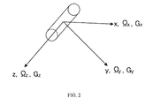
- FIG. 2 schematically shows sensor coordinate axes
- FIG. 3 schematically shows an earth model
- FIG. 4 is an explanatory view of azimuth
- FIG. 5 shows a flow chart of another embodiment of azimuth measurement methods using the three gyro sensors and the three accelerometers
- FIG. 6 shows definitions of the rotation angles of the gyro sensors
- FIGS. 7A and 7B show a flow chart of yet another embodiment of azimuth measurement methods using the three gyro sensors and the three accelerometers;
- FIG. 8 shows a sinusoidal curve fitting method in the case of XY-axis gyro sensor
- FIG. 9 shows an example of earth rate components obtained by the sinusoidal curve fitting method of FIG. 8 ;
- FIGS. 10A and 10B show a flow chart of yet another embodiment of azimuth measurement methods using the three gyro sensors and the three accelerometers;
- FIG. 11 shows definitions of rotation angles of a gyro sensor coordinate frame
- FIG. 12 shows azimuth computed using the equations of earth rate vector ⁇ 0 ;
- FIG. 13 shows a theta angle dependency of azimuth error obtained by computer simulation
- FIG. 14 shows a computer simulation of a comparative example
- FIG. 15 shows another computer simulation of a comparative example
- FIG. 16 shows a sensor system including three orthogonal axis gyro sensors and three orthogonal axis accelerometers;
- FIG. 17 shows a block diagram of electric system of the sensor system
- FIG. 18 shows a sensor system including two orthogonal axis gyro sensors and three orthogonal axis accelerometers;
- FIG. 19 shows an example of a flow chart of data processing for azimuth measurements by using the sensor system with the two or three orthogonal axis gyro sensors
- FIG. 20 shows a sensor system including a single gyro sensor and three accelerometers
- FIG. 21 shows a sensor system including three orthogonal axis gyro sensors and three accelerometers.
- FIG. 1 shows a flow chart of an embodiment of azimuth measurement methods according to the present invention.
- a system for azimuth measurements including one-axis gyro sensor, which can output signals relating to rotation angular rate, is located at an azimuth measuring position in downhole.
- the gyro sensor is set so as to align its input axis to a predetermined angular orientation parallel to a horizontal plane perpendicular to a gravity direction. Bias of the gyro sensor is cancelled out by calculating a difference between two measurement data at opposite angular orientations.
- ⁇ 180°
- the azimuth measurements include a plurality of computation procedures based on following equations:
- ⁇ (0°) — 1 , ⁇ (180°) — 2 , ⁇ (0°) — 3 are gyro sensor outputs at 0°, 180° and 0° angular orientations;
- ⁇ E is an earth rate component
- ⁇ B is gyro bias assumed as a linear function of time (t).
- n gyro random noise
- the measurement procedures include a first data measurement ⁇ (0°) — 1 from the gyro sensor with the input axis aligned to an first angular orientation at 0°, flipping the input axis of the gyro sensor, and a second data measurement ⁇ (180°) — 2 from the gyro sensor with the input axis aligned to the second angular orientation at 180° (S 101 -S 104 ).
- the measurement procedures also include another flipping to return the input axis to the first angular orientation and a third data measurement ⁇ (0°) — 3 from the gyro sensor with the input axis aligned to the first angular orientation at 0° (S 105 , S 106 ).
- bias-cancel process by flipping The above-mentioned data process of measurement procedures using the first, second and third data is hereinafter referred to as “bias-cancel process by flipping”.
- Each measurement of data from the gyro sensor may take as long as possible to acquire sufficient length of the data to improve signal-to-noise ratio by averaging or an adequate smoothing. A too long data acquisition however causes too much bias uncertainty for a linear interpolation to cancel out.
- the acquisition time may be determined such that it can cover one cycle of a low frequency bias fluctuation. All three successive measurement steps for the three data ⁇ (0°) — 1 , ⁇ (180°) — 2 and ⁇ (0°) — 3 may be completed during the time in which the bias drift can be regarded linear so that the bias is sufficiently cancelled out by the measurement procedures.
- the gyro sensor in this embodiment is well pre-calibrated in terms of scale factor before azimuth measurements are performed in downhole. Since the earth rate component ( ⁇ N ) in the north direction on the horizontal plane is known from latitude at the place, azimuth (A z ) of the input axis direction can be calculated (S 109 ) with the following equation:
- a Z arc ⁇ ⁇ cos ⁇ ( ⁇ E ⁇ N ) . ( 6 )
- a system including three orthogonal axis (x, y, z) gyro sensors and three orthogonal axis (x, y, z) accelerometers is used.
- These gyro sensors and accelerometers are located at an azimuth measuring position for azimuth measurements in downhole.
- the gyro sensors can detect three earth rate components ( ⁇ x, ⁇ y, ⁇ z) to determine the earth rate vector ( ⁇ 0 ).
- the accelerometers can detect three gravity vector components (G x , G y , G z ) to determine the gravity vector (G).
- the earth rate vector ( ⁇ 0 ), the north-pointing vector, the gravity vector (G), and latitude angle ( ⁇ ) have a relationship as shown in FIG. 3 .
- the gyro sensors measure the three earth rate components ( ⁇ x, ⁇ y, ⁇ z) to determine the earth rate vector ( ⁇ 0 ) with respect to a predetermined sensor coordinate system with three orthogonal axes (x, y, z).
- the accelerometers measure three gravity vector components (Gx, Gy, Gz) to determine the gravity vector (G) with respect to the sensor coordinate system.
- an azimuth (A z ) is defined as an angle between the Z-axis projection and the earth rate vector projection onto the horizontal plane.
- FIG. 5 shows a flow chart of an azimuth measurement method according to the embodiment using the three gyro sensors and the three accelerometers.
- bias of each gyro sensor is cancelled out by calculating a difference between two measurement data at two opposite angular orientations of the gyro input axis.
- the bias does not change its sign but the earth rate signal does.
- the azimuth measurement includes a plurality of procedures based on the aforementioned equations (1)-(5).
- the measurement procedures using one of the gyro sensors located at an azimuth measuring position in downhole include the aforementioned bias-cancel process by flipping (S 201 -S 208 ).
- Each measurement of data from the gyro sensors may take as long as possible to acquire sufficient length of the data to improve signal-to-noise ratio by averaging or an adequate smoothing. A too long data acquisition however causes too much bias uncertainty for a linear interpolation to cancel out.
- the acquisition time may be determined such that it can cover one cycle of a low frequency bias fluctuation. All three successive measurement steps for the three data ⁇ (0°) — 1 , ⁇ (180°) — 2 and ⁇ (0°) — 3 may be completed during the time in which the bias can be regarded linear so that the bias is sufficiently cancelled out by the measurement procedures.
- each gyro sensor flipping each of the input axes of three gyro sensors, three orthogonal earth rate components of the earth rate vector are obtained (S 209 , S 210 , S 211 ).
- the number of repeating the measurements may be determined by averaging or smoothing time for noise reduction.
- the earth rate vector is determined with respect to the orthogonal sensor axis coordinates (S 212 ).
- each gyro sensor may be pre-calibrated with sufficient accuracy in terms of the scale factor and the misalignment.
- a z - arc ⁇ ⁇ tan ⁇ ( ⁇ x ⁇ G y - ⁇ y ⁇ G x ⁇ z + G z ⁇ sin ⁇ ( latitude ) ) . ( 7 )
- a system including three gyro sensors and three orthogonal axis accelerometers is used, and a scale factor error is calibrated.
- a YZ-gyro sensor, an XY-gyro sensor and a ZX-gyro sensor are used as shown in FIG. 6 .
- the input axis of the YZ-gyro sensor is rotatable about X-axis on YZ-plane (plane-A).
- the input axis of the XY-gyro sensor is rotatable about Z-axis on XY-plane (plane-B).
- the input axis of the ZX-gyro sensor is rotatable about Y-axis on ZX-plane (plane-C).
- FIGS. 7A and 7B show a flow chart of an azimuth measurement method according to the embodiment using the three gyro sensors and the three accelerometers.
- the azimuth measurement includes a plurality of procedures based on the aforementioned equations (1)-(5).
- the measurement procedures using the YZ-gyro sensor located at an azimuth measuring position in downhole include the aforementioned bias-cancel process by flipping (S 201 -S 208 ).
- the YZ-gyro sensor is rotated by 90 degree about X-axis so as to align the input axis to another first angular orientation and the steps of S 301 -S 308 are repeated to obtain the earth rate component ⁇ 90 ° at the another first angular orientation of 90° (S 309 , S 310 ).
- the two earth rate components of ⁇ 0 ° and ⁇ 90 ° are set as ⁇ Ay and ⁇ Az respectively for determination of the earth rate vector (S 311 ) and the measurement for the YZ-gyro sensor is completed.
- the measurements of earth rate components of ⁇ 0 ° and ⁇ 90 ° are performed with the XY-gyro sensor so as to set ⁇ Bx and ⁇ By (S 313 ).
- the measurements of earth rate components of ⁇ 0 ° and ⁇ 90 ° are also performed with the ZX-gyro sensor so as to set ⁇ Cz and ⁇ Cx (S 314 ).
- three redundant earth rate vectors calibrated with a ratio of sensitivity between a pair of the gyro sensors can be derived (S 315 ) as shown in following equations:
- the ratio of sensitivity between a pair of the gyro sensors is determined by a ratio of earth rate components obtained at a common first angular orientation.
- the ratio of sensitivity between the YZ-gyro sensor and the XY-gyro sensor is determined by dividing a Y-axis earth rate component ⁇ By another Y-axis earth rate component ⁇ Ay .
- a Z-axis earth rate component measured by the YZ-gyro sensor is corrected by multiplied by the ratio of sensitivity ( ⁇ By / ⁇ Ay ).
- Dividing an earth rate component by another earth rate component may result in a large azimuth error if an absolute value of the earth rate component in the denominator is too small because each sensor output may contain an error.
- a corresponding data obtained from other gyro sensor is used based on a selection criterion with following three equations (11), (12) and (13) (See steps of S 316 -S 320 in FIG. 7B ).
- three gravity vector components (Gx, Gy, Gz) of the gravity vector at the azimuth measuring position in downhole are acquired from the accelerometers (S 321 ).
- the measured earth rate vector ⁇ 0 ( ⁇ x, ⁇ y, ⁇ z) and gravity vector G (Gx, Gy, Gz) are normalized to be unit vectors, respectively (S 322 ).
- the azimuth (A z ) defined with respect to the Z-axis direction can be calculated (S 323 ) with the foregoing equation (7).
- FIG. 8 shows a plurality of discrete target angular orientations used in another embodiment of the present invention.
- the gyro rotation plane is horizontal, it is possible to determine azimuth by using one gyro sensor (for example, XY-gyro sensor).
- a stationary measurement of an earth rate component including the bias-cancel process by flipping is performed respectively at every target angular orientation as shown in FIG. 8 . That is, data acquisition from the gyro sensor is repeated at each of the discrete target angular orientations divided in the range of 360° on the sensor rotation plane under a stationary condition.
- a model sinusoidal curve is fit to the data to determine the earth rate components, as shown in FIG. 9 .
- These earth rate components determine the direction of the projection of the earth rate vector onto the horizontal sensor rotation plane. Then azimuth is determined as an angle between this projection and the gyro input axis at 0°.
- the present embodiment is especially useful for a relatively low grade and single axis gyro sensor.
- continuous rotation of the gyro sensor is not required.
- the rotation of the gyro sensor is stopped at every target angular orientations to measure an earth rate component under a stationary condition for improving signal-to-noise ratio.
- FIGS. 10A and 10B show a flow chart of an azimuth measurement method according to the embodiment using the three gyro sensors with the sensor rotation axis perpendicular to each other and the three orthogonal axis accelerometers.
- a calibration with respect to a ratio of sensitivity and a model curve fitting are performed.
- a plurality of measurements of earth rate components is taken in various angular orientations by using three gyro sensors in an arbitrary attitude of the sensor system (S 414 , S 415 , S 416 ).
- the gyro sensor is rotated about Z-axis to align its input axis so as to the next angular orientation and repeats the sequence (S 402 -S 408 ) for measurements of earth rate components on XY plane until the total data covers a plurality of discrete angular orientations in the angular range of 360 degrees (S 409 , S 410 ).
- the same measurements of earth rate components are performed on each sensor rotation plane (YZ plane or ZX plane) (S 415 , S 416 ).
- a sinusoidal curve fitting is applied to the earth rate component data (S 411 ).
- a and B are fitting parameters.
- the earth rate components at the angular orientations of the sensor axes are obtained directly from the fitting parameters, A and B (S 412 ).
- the two values of ⁇ Ay and ⁇ By may be different because of a discrepancy of in sensor sensitivities between the XY gyro sensor and the YZ gyro sensor.
- a ZX-gyro sensor rotatable on the ZX plane can be also used to determine the fitting parameters.
- earth rate components are then determined by the above equations (S 414 -S 416 ).
- three pairs of the two fitting parameters determined on common sensor axes can be selected. Each pair determines the same earth rate vector ⁇ 0 (S 417 ), as shown in equations (21), (22) and (23).
- each ratio of sensitivities between two gyro sensors selected among the XY-gyro sensor, YZ-gyro sensor and ZX-gyro sensor is determined by dividing an earth rate component by another earth rate component.
- a corresponding data obtained from other gyro sensor is used based on a selection criterion with the foregoing three equations (11), (12) and (13) (See steps of S 418 -S 3422 in FIG. 10B ).
- the earth rate vector in the sensor axis coordinate is then projected onto the horizontal plane to determine an azimuth of a target direction at certain latitude.
- the horizontal plane is determined as a plane perpendicular to a gravity vector.
- the gravity vector G can be determined with three orthogonal accelerometers (S 423 ).
- the measured earth rate vector ⁇ 0 and gravity vector G are normalized to be unit vectors, respectively (S 424 ).
- the x′ component of ⁇ is
- the azimuth (A z ) is then determined (S 425 in FIG. 10B ) using the following equation:
- a z - arctan ⁇ ( ⁇ x ⁇ z ) , ( 29 ) where ⁇ x and ⁇ z are earth rate components when x- and y-axes are on a horizontal surface.
- FIG. 11 shows definitions of rotation angles of a gyro sensor coordinate frame including three orthogonal axis gyro sensors and three orthogonal axis accelerometers used in computer simulation.
- the rotation angles are defined according to a North-East-Down (NED) coordinate system fixed on the earth.
- NED North-East-Down
- the computer simulation is performed to simulate gyro error propagation to the earth rate vector and then to azimuth when a sensor system including the gyro sensor takes various attitudes with respect to the gravity direction.
- FIG. 12 shows an azimuth computed by using the equations (21), (22) and (23) of earth rate vector ⁇ 0 and the equation (28) of azimuth for all combination of pitch rotation angle ( ⁇ ) and yaw rotation angle ( ⁇ ) at roll rotation angle ( ⁇ ) of 0°.
- azimuth computation of FIG. 12 even though wrong scale factors are assumed in three gyro sensors intentionally, the present method can compute correct azimuth in any inclination.
- the computation simulation can verify that the present method computes correct azimuth for any incremental angles of the roll rotation angle ⁇ .
- FIG. 16 shows an example of a sensor system to realize the present method described above.
- FIG. 17 shows a block diagram of electric system of the sensor system.
- the sensor system 10 includes a housing 100 , three orthogonal axis gyro sensors 200 X, 200 Y, 200 Z, an accelerometer module 300 including three orthogonal axis accelerometers 300 X, 300 Y, 300 Z, a driving mechanism 400 for the gyro sensors to flip and/or rotate each input axis of the gyro sensors.
- the driving mechanism 400 flips and/or rotates each of the gyro sensors using a single motor 401 (preferably a step motor) and gears to transport the rotating force to each rotation axis of the gyro sensors.
- the sensor system 10 also includes a controller 500 for the driving mechanism, a data processing unit 600 and a power supply unit 700 .
- the data processing unit 600 includes a computer having a processor 601 and a memory 602 .
- the memory 602 stores a program having instructions for the azimuth measurements.
- the gyro sensors 200 X, 200 Y, 200 Z, the accelerometers 300 X, 300 Y, 300 Z, the driving mechanism 400 , the controller 500 for the driving mechanism 400 , the data processing unit 600 and the power supply unit 700 are installed in the housing 100 .
- An angle position sensor 402 may be preferably provided in order to detect a rotation angle position of a rotation axis of the motor 401 or the gyro sensor. By using the detected rotation angle position, the angular orientation of each input axis of the gyro sensors 200 X, 200 Y, 200 Z can be identified.
- the angle position sensor 402 may be used to monitor an angular rotation position of the motor axis. This monitoring the angular rotation position allows the sensor system 10 to return each gyro sensor at a home position and set each input axis of the gyro sensors parallel to a predetermined home angular orientation (original angular orientation), whenever the system power is turned on. In addition, it is important to monitoring the angular rotation position during the azimuth measurement for reliability of the sensor system.
- the sensor system 10 includes only two orthogonal axis gyro sensors 200 X, 200 Z and three orthogonal axis accelerometers (See FIG. 18 ).
- FIG. 19 shows an example of a flow chart of data processing for azimuth measurements by using the sensor system 10 with the two or three orthogonal axis gyro sensors.
- the input axes of the gyro sensors are orthogonal to each other.
- At least one program having instructions for the data processing is stored in the memory 602 of the data processing unit 600 .
- the sensor system 10 is stationary located at an azimuth measuring position in downhole before azimuth measurements.
- a first data from each of the gyro sensors with an input axis aligned to a first angular orientation (0°) is acquired (S 1001 ).
- a second data from each of the gyro sensors with the input axis aligned to a second angular orientation (180°) opposite to the first angular orientation is acquired (S 1002 ).
- a third data from each of the gyro sensors with the input axis aligned to the original first angular orientation (0°) is acquired (S 1003 ).
- An earth rate component at the first angular orientation is determined (S 1004 ) using the aforementioned equations (1)-(5) by following steps of:
- the acquisition of the three data and the determination of the earth rate component for each of the gyro sensors are repeated at a plurality of discrete target angular orientations as shown in FIG. 8 on each of the sensor rotation planes (S 1005 ).
- Components of an earth rate vector with respect to a predetermined orthogonal sensor coordinates are determined based on based on a result of the sinusoidal curve fitting (S 1007 ).
- a ratio of sensitivity of a pair of the gyro sensors is determined (S 1008 ).
- a gravity direction with respect to the orthogonal sensor coordinates is determined based on acceleration data of gravity acquired with the accelerometers (S 1010 ).
- a north direction is determined by projecting the earth rate vector onto a horizontal plane perpendicular to the gravity direction (S 1011 ).
- an azimuth of a target direction on the horizontal plane is determined based on the north direction (S 1012 ).
- the single gyro sensor 200 is used to determine earth rate components on three orthogonal axes sequentially. On each axis, flipping the input axis of the gyro sensor is conducted to cancel out the bias error. The measurements with the single gyro sensor 200 are free from the scale factor error (See FIG. 20 ).
- the dynamic range may be set so as to cover not only the earth rate but also bias drift due to environmental temperature change.
- the three accelerometers 300 X, 300 Y, 300 Z may be either conventional Q-flex types or MEMS type accelerometers.
- gyro sensors 200 X, 200 Y, 200 Z used for the azimuth measurements
- a MEMS gyro sensor used for the azimuth measurements
- a MEMS gyro sensor of ring oscillating type may be preferably used in terms of the accuracy, measurement robustness in environmental vibration conditions.
- the sensor peripheral circuit may be configured to dispose an analog circuit portion of the sensor peripheral circuit as close as to the gyro sensor and to output only digital signals to the wires.
- the analog circuit portion may be included together with the gyro sensor head on a flipped stage of the driving mechanism and flipped or rotated together with the sensor head.
- the driving mechanism 400 may be configured with only a single motor 401 to flip and/or rotate each input axis of three orthogonal axis gyro sensors 200 X, 200 Y, 200 Z.
- the rotation force is transmitted through a driving force transmitting mechanism such as a gearbox.
- the azimuth measurements with the gyro sensors are preferably conducted under a stationary condition, not done while the gyro sensor is rotating. Therefore, the angular orientation accuracy is more important in this configuration.
- the driving mechanism 400 may be also configured with separate motors 401 X, 401 Y and 401 Z. Each separate motor may drive each gyro sensor directly without a gearbox. Angle position sensors 402 X, 402 Y, 402 Z are provided in order to detect rotation angle positions of rotation axes of the motor 401 X, 401 Y, 401 Z, respectively.
- the driving mechanism 400 with separate motors 401 X, 401 Y, 401 Z may be used to minimize angle errors due to back lash of the gear box in the sensor system with relatively wide physical space for installation. The backlash error causes directly azimuth error (See FIG. 21 ).
- Any gyro sensor has more or less temperature sensitivity in its output. Especially downhole condition in oilfield temperature is changing.
- Some pre-calibration of the gyro sensor output against temperature using equation for temperature compensation with at least one coefficient may be performed before azimuth measurement in downhole.
- the coefficient obtained by the pre-calibration may be used to compensate the sensor output by monitoring temperature with a temperature sensor in the sensor part and/or the peripheral circuit. This kind of temperature compensation may be also performed for output data of the accelerometers.
- the temperature sensors can be installed on the gyro sensor and its analog circuit. The compensation is conducted to compensate temperature dependency of scale factor, bias and misalignment using pre-calibration coefficients of the temperature dependency of each item.
- Each output of three-orthogonal axis gyro sensors, three-orthogonal axis accelerometers, and temperature sensors for the gyro sensors and accelerometers is input into the data processing unit.
- the data processing of the output data may be conducted by a digital signal processing unit (DSP) or a field programmable gate array (FPGA).
- DSP digital signal processing unit
- FPGA field programmable gate array
- the power unit may be configured with a battery.
- the use of battery has an advantage in MWD and LWD applications, where no electric power is supplied through the cables of MWD and LWD tools.
- the sensor system may be installed in a downhole tool.
- the Z-axis defined as parallel to a tool axis of the downhole tool is almost vertical, azimuth cannot be defined because of no projection of the Z-axis onto the horizontal plane.
- the projection of other alternative axis onto the horizontal plane may be used to determine an angle from the north direction.
- the alternative axis may be defined so as to be normal to a reference face on side surface, which is called tool face.
- the direction of the tool face is determined with gyro sensors and accelerometers in the manner explained above during the tool is under a stationary condition. Once the tool starts moving in downhole, an additional gyro sensor installed in the tool monitors the tool rotation about Z-axis.
- the additional gyro sensor with an input axis parallel to a tool axis defined in the tool having the gyro sensors for azimuth measurements may be useful to monitor the tool rotation.
- Dynamic range of the added gyro sensor is large enough to cover the maximum angular rate of the tool rotation.
- Angular rate output of the additional gyro sensor is integrated to calculate rotation angles of the tool.
Abstract
Description
where
Ωi =A cos θi +B sin θi, (14)
where Ωi is an earth rate component at an angular orientation θi. A and B are fitting parameters.
A=ΩAx, (15)
B=ΩAy, (16)
where ΩAx is an X-axis component of the earth rate vector measured by the XY-gyro sensor, and ΩAy is a Y-axis component of the earth rate vector measured by the XY-gyro sensor (S414).
A=ΩBy, (17)
B=ΩBz, (18)
where ΩBy is a Y-axis component of the earth rate vector measured by the YZ-gyro sensor, and ΩBz is a Z-axis component of the earth rate vector measured by the YZ-gyro sensor (S415).
A=ΩCz, (19)
B=ΩCx, (20)
where ΩCz is a Z-axis component of the earth rate vector measured by the ZX-gyro sensor, and ΩCx is an X-axis component of the earth rate vector measured by the ZX-gyro sensor (S416).
The perpendicular unit vector of the Z-axis projection onto the horizontal surface, x′, is
The z′ component of Ω is
The x′ component of Ω is
Note that if the denominator in the blanket vanishes, arctangent gives 90 degrees whatever the numerator is. This corresponds to the situation that the Z-axis is parallel to the gravity vector and azimuth cannot be defined because no Z-axis projection is available on the horizontal surface.
where Ωx and Ωz are earth rate components when x- and y-axes are on a horizontal surface.
Claims (59)
Ωi =A cos θi +B sin θi
Ωi =A cos θi +B sin θi
Priority Applications (2)
| Application Number | Priority Date | Filing Date | Title |
|---|---|---|---|
| US12/233,592 US7801704B2 (en) | 2008-05-15 | 2008-09-19 | Method and system for azimuth measurements using gyro sensors |
| PCT/IB2009/005543 WO2009138842A1 (en) | 2008-05-15 | 2009-05-11 | Method and system for azimuth measurements using gyro sensors |
Applications Claiming Priority (2)
| Application Number | Priority Date | Filing Date | Title |
|---|---|---|---|
| US5364608P | 2008-05-15 | 2008-05-15 | |
| US12/233,592 US7801704B2 (en) | 2008-05-15 | 2008-09-19 | Method and system for azimuth measurements using gyro sensors |
Publications (2)
| Publication Number | Publication Date |
|---|---|
| US20090287451A1 US20090287451A1 (en) | 2009-11-19 |
| US7801704B2 true US7801704B2 (en) | 2010-09-21 |
Family
ID=41316963
Family Applications (1)
| Application Number | Title | Priority Date | Filing Date |
|---|---|---|---|
| US12/233,592 Active 2028-12-24 US7801704B2 (en) | 2008-05-15 | 2008-09-19 | Method and system for azimuth measurements using gyro sensors |
Country Status (2)
| Country | Link |
|---|---|
| US (1) | US7801704B2 (en) |
| WO (1) | WO2009138842A1 (en) |
Cited By (7)
| Publication number | Priority date | Publication date | Assignee | Title |
|---|---|---|---|---|
| US20090119937A1 (en) * | 2007-11-13 | 2009-05-14 | Watson William S | Method and system for heading indication with drift compensation |
| US20110126647A1 (en) * | 2009-12-01 | 2011-06-02 | Dave Newland | Rate of turn signal generator with drift compensation |
| US8099876B1 (en) * | 2008-11-21 | 2012-01-24 | The Boeing Company | Azimuth determination system and method therefor |
| US20120084050A1 (en) * | 2010-10-05 | 2012-04-05 | Shigeru Sato | Method and System for Azimuth Measurements Using a Gyroscope Unit |
| US9631446B2 (en) | 2013-06-26 | 2017-04-25 | Impact Selector International, Llc | Impact sensing during jarring operations |
| US9951602B2 (en) | 2015-03-05 | 2018-04-24 | Impact Selector International, Llc | Impact sensing during jarring operations |
| US10982530B2 (en) | 2016-04-03 | 2021-04-20 | Schlumberger Technology Corporation | Apparatus, system and method of a magnetically shielded wellbore gyroscope |
Families Citing this family (22)
| Publication number | Priority date | Publication date | Assignee | Title |
|---|---|---|---|---|
| WO2008101285A1 (en) * | 2007-02-20 | 2008-08-28 | Commonwealth Scientific & Industrial Research Organisation | Method and apparatus for modelling the interaction of a drill bit with the earth formation |
| US7845085B2 (en) * | 2007-07-12 | 2010-12-07 | Textron Systems Corporation | Identifying a directional reference using rate gyros oriented along different axes |
| US7832111B2 (en) * | 2008-09-09 | 2010-11-16 | Memsic, Inc. | Magnetic sensing device for navigation and detecting inclination |
| US7712223B2 (en) * | 2008-09-29 | 2010-05-11 | Schlumberger Technology Corporation | Apparatus for azimuth measurements using gyro sensors |
| GB0914661D0 (en) | 2009-08-21 | 2009-09-30 | Antech Ltd | System for derermination of downhole position |
| EP2577228B1 (en) | 2010-05-25 | 2023-10-11 | Reflex Instruments Asia Pacific Pty Ltd | Down hole surveying tool |
| US9182211B2 (en) * | 2011-12-06 | 2015-11-10 | Honeywell International Inc. | Field interchangable boresight mounting system and calibration method |
| WO2013102237A2 (en) * | 2012-01-04 | 2013-07-11 | Imdex Global B.V. | Navigation device and method for surveying and directing a borehole under drilling conditions |
| US9664027B2 (en) * | 2012-07-20 | 2017-05-30 | Merlin Technology, Inc. | Advanced inground operations, system and associated apparatus |
| CN102879832B (en) * | 2012-09-21 | 2015-05-20 | 中国人民解放军国防科学技术大学 | Non-alignment error correction method used for geomagnetic element measuring system |
| WO2014105025A1 (en) | 2012-12-27 | 2014-07-03 | Halliburton Energy Services, Inc. | Determining gravity toolface and inclination in a rotating downhole tool |
| IL237971A (en) * | 2015-03-26 | 2016-10-31 | Gandelsman Mark | Device and method for determining the relative orientation between two different locations |
| SE538872C2 (en) | 2015-05-04 | 2017-01-17 | Lkab Wassara Ab | Gyro-based surveying tool and method for surveying |
| EP3443299A4 (en) * | 2016-04-11 | 2020-07-29 | HRL Laboratories, LLC | Gyromagnetic geopositioning system |
| CN106840205B (en) * | 2017-01-19 | 2020-05-15 | 北京小鸟看看科技有限公司 | Gyroscope calibration compensation method and device and virtual reality head-mounted equipment |
| CN107203234A (en) * | 2017-06-15 | 2017-09-26 | 北京航空航天大学 | A kind of integrated magnetic resonance gyroscope temperature closed loop numerical control system |
| CN108759874A (en) * | 2018-07-30 | 2018-11-06 | 武汉华之源网络科技有限公司 | Detecting devices angle of turning relative error measurement method peculiar to vessel |
| CN110207724B (en) * | 2019-07-04 | 2020-09-11 | 苏州邈航科技有限公司 | IMU array type full-temperature calibration method and calibration device |
| CN113062721B (en) * | 2021-03-15 | 2022-11-18 | 重庆工程学院 | Total temperature compensation method and system of logging instrument for exploration |
| CN113375692B (en) * | 2021-05-11 | 2022-08-12 | 北京航天时代光电科技有限公司 | Method for rapidly evaluating calibration precision of fiber-optic gyroscope |
| CN113432605B (en) * | 2021-06-30 | 2023-03-31 | 河北科技大学 | North-seeking method and system based on fiber-optic gyroscope |
| CN113899323B (en) * | 2021-11-08 | 2023-08-25 | 中国计量科学研究院 | Multi-axis turntable angle positioning error detection method based on single-axis laser gyro angle meter |
Citations (17)
| Publication number | Priority date | Publication date | Assignee | Title |
|---|---|---|---|---|
| EP0175298A2 (en) | 1984-09-14 | 1986-03-26 | Develco, Incorporated | Borehole sensing tool with optical rotation sensor |
| DE19505855C1 (en) | 1995-02-21 | 1996-02-08 | Dmt Gmbh | Angled borehole measuring device |
| GB2296772A (en) | 1994-12-19 | 1996-07-10 | Gyrodata Inc | Surveying a well borehole by means of a rate gyro using an error nulling system |
| US5821414A (en) * | 1997-02-07 | 1998-10-13 | Noy; Koen | Survey apparatus and methods for directional wellbore wireline surveying |
| WO1999028594A1 (en) | 1997-12-04 | 1999-06-10 | Baker Hughes Incorporated | Measurement-while-drilling assembly using gyroscopic devices and methods of bias removal |
| GB2351807A (en) | 1999-07-01 | 2001-01-10 | Schlumberger Holdings | Reverse inertial navigation method for high precision wellbore surveying |
| US6381853B1 (en) | 1997-03-27 | 2002-05-07 | Terrence James Parke | Rotary cutting device having adjustable tension |
| US6453239B1 (en) | 1999-06-08 | 2002-09-17 | Schlumberger Technology Corporation | Method and apparatus for borehole surveying |
| US20020174720A1 (en) | 2001-04-17 | 2002-11-28 | Donato Cardarelli | MEMS gyroscope and accelerometer with mechanical reference |
| US6529834B1 (en) | 1997-12-04 | 2003-03-04 | Baker Hughes Incorporated | Measurement-while-drilling assembly using gyroscopic devices and methods of bias removal |
| US20030056381A1 (en) * | 1997-02-07 | 2003-03-27 | James Brosnahan | Survey apparatus and methods for directional wellbore surveying |
| US6633816B2 (en) | 2000-07-20 | 2003-10-14 | Schlumberger Technology Corporation | Borehole survey method utilizing continuous measurements |
| JP2006038650A (en) | 2004-07-27 | 2006-02-09 | Sumitomo Precision Prod Co Ltd | Posture measuring method, posture controller, azimuth meter and computer program |
| JP2006177909A (en) | 2004-12-24 | 2006-07-06 | Sumitomo Precision Prod Co Ltd | Bias measurement method for inertial sensor, and device thereof |
| US7117605B2 (en) | 2004-04-13 | 2006-10-10 | Gyrodata, Incorporated | System and method for using microgyros to measure the orientation of a survey tool within a borehole |
| WO2007005637A2 (en) | 2005-06-30 | 2007-01-11 | Weatherford Canada Partnership | Single sensor element positioned in multiple controlled orientations |
| US7234540B2 (en) | 2003-08-07 | 2007-06-26 | Baker Hughes Incorporated | Gyroscopic steering tool using only a two-axis rate gyroscope and deriving the missing third axis |
-
2008
- 2008-09-19 US US12/233,592 patent/US7801704B2/en active Active
-
2009
- 2009-05-11 WO PCT/IB2009/005543 patent/WO2009138842A1/en active Application Filing
Patent Citations (17)
| Publication number | Priority date | Publication date | Assignee | Title |
|---|---|---|---|---|
| EP0175298A2 (en) | 1984-09-14 | 1986-03-26 | Develco, Incorporated | Borehole sensing tool with optical rotation sensor |
| GB2296772A (en) | 1994-12-19 | 1996-07-10 | Gyrodata Inc | Surveying a well borehole by means of a rate gyro using an error nulling system |
| DE19505855C1 (en) | 1995-02-21 | 1996-02-08 | Dmt Gmbh | Angled borehole measuring device |
| US5821414A (en) * | 1997-02-07 | 1998-10-13 | Noy; Koen | Survey apparatus and methods for directional wellbore wireline surveying |
| US20030056381A1 (en) * | 1997-02-07 | 2003-03-27 | James Brosnahan | Survey apparatus and methods for directional wellbore surveying |
| US6381853B1 (en) | 1997-03-27 | 2002-05-07 | Terrence James Parke | Rotary cutting device having adjustable tension |
| WO1999028594A1 (en) | 1997-12-04 | 1999-06-10 | Baker Hughes Incorporated | Measurement-while-drilling assembly using gyroscopic devices and methods of bias removal |
| US6529834B1 (en) | 1997-12-04 | 2003-03-04 | Baker Hughes Incorporated | Measurement-while-drilling assembly using gyroscopic devices and methods of bias removal |
| US6453239B1 (en) | 1999-06-08 | 2002-09-17 | Schlumberger Technology Corporation | Method and apparatus for borehole surveying |
| GB2351807A (en) | 1999-07-01 | 2001-01-10 | Schlumberger Holdings | Reverse inertial navigation method for high precision wellbore surveying |
| US6633816B2 (en) | 2000-07-20 | 2003-10-14 | Schlumberger Technology Corporation | Borehole survey method utilizing continuous measurements |
| US20020174720A1 (en) | 2001-04-17 | 2002-11-28 | Donato Cardarelli | MEMS gyroscope and accelerometer with mechanical reference |
| US7234540B2 (en) | 2003-08-07 | 2007-06-26 | Baker Hughes Incorporated | Gyroscopic steering tool using only a two-axis rate gyroscope and deriving the missing third axis |
| US7117605B2 (en) | 2004-04-13 | 2006-10-10 | Gyrodata, Incorporated | System and method for using microgyros to measure the orientation of a survey tool within a borehole |
| JP2006038650A (en) | 2004-07-27 | 2006-02-09 | Sumitomo Precision Prod Co Ltd | Posture measuring method, posture controller, azimuth meter and computer program |
| JP2006177909A (en) | 2004-12-24 | 2006-07-06 | Sumitomo Precision Prod Co Ltd | Bias measurement method for inertial sensor, and device thereof |
| WO2007005637A2 (en) | 2005-06-30 | 2007-01-11 | Weatherford Canada Partnership | Single sensor element positioned in multiple controlled orientations |
Cited By (9)
| Publication number | Priority date | Publication date | Assignee | Title |
|---|---|---|---|---|
| US20090119937A1 (en) * | 2007-11-13 | 2009-05-14 | Watson William S | Method and system for heading indication with drift compensation |
| US7877887B2 (en) * | 2007-11-13 | 2011-02-01 | Watson Industries, Inc. | Method and system for heading indication with drift compensation |
| US8099876B1 (en) * | 2008-11-21 | 2012-01-24 | The Boeing Company | Azimuth determination system and method therefor |
| US20110126647A1 (en) * | 2009-12-01 | 2011-06-02 | Dave Newland | Rate of turn signal generator with drift compensation |
| US20120084050A1 (en) * | 2010-10-05 | 2012-04-05 | Shigeru Sato | Method and System for Azimuth Measurements Using a Gyroscope Unit |
| US9435649B2 (en) * | 2010-10-05 | 2016-09-06 | Schlumberger Technology Corporation | Method and system for azimuth measurements using a gyroscope unit |
| US9631446B2 (en) | 2013-06-26 | 2017-04-25 | Impact Selector International, Llc | Impact sensing during jarring operations |
| US9951602B2 (en) | 2015-03-05 | 2018-04-24 | Impact Selector International, Llc | Impact sensing during jarring operations |
| US10982530B2 (en) | 2016-04-03 | 2021-04-20 | Schlumberger Technology Corporation | Apparatus, system and method of a magnetically shielded wellbore gyroscope |
Also Published As
| Publication number | Publication date |
|---|---|
| WO2009138842A1 (en) | 2009-11-19 |
| US20090287451A1 (en) | 2009-11-19 |
Similar Documents
| Publication | Publication Date | Title |
|---|---|---|
| US7801704B2 (en) | Method and system for azimuth measurements using gyro sensors | |
| US7117605B2 (en) | System and method for using microgyros to measure the orientation of a survey tool within a borehole | |
| US7730625B2 (en) | Gyroscopically-oriented survey tool | |
| Aggarwal et al. | A standard testing and calibration procedure for low cost MEMS inertial sensors and units | |
| EP2068118B1 (en) | Method and system for heading indication with drift compensation | |
| US7231825B2 (en) | Accelerometer based tilt sensor and method for using same | |
| RU2269813C2 (en) | Method for calibrating parameters of platform-less inertial measuring module | |
| US20160116302A1 (en) | Method for comparing two inertial units integral with a same carrier | |
| US6799459B2 (en) | Gravity gradiometer and method for calculating a gravity tensor with increased accuracy | |
| US7933717B2 (en) | Method for elaborating navigation parameters and vertical of a place | |
| US20190086573A1 (en) | Method for detecting an anomaly in the context of using a magnetic locating device | |
| Yang et al. | A temperature compensation model for low cost quartz accelerometers and its application in tilt sensing | |
| Noureldin et al. | Inertial navigation system | |
| US9217640B2 (en) | Gyroscopic measurement in a navigation system | |
| US5841018A (en) | Method of compensating for installation orientation of an attitude determining device onboard a craft | |
| EP0175298A2 (en) | Borehole sensing tool with optical rotation sensor | |
| US20210026037A1 (en) | Wellbore Survey Tool Using Coriolis Vibratory Gyroscopic Sensors | |
| US20200132458A1 (en) | Wellbore Survey Tool Using Coriolis Vibratory Gyroscopic Sensors | |
| US11614329B2 (en) | Method for monitoring the performance of inertial measurement units | |
| RU2779274C1 (en) | Method for measuring errors of the initial alignment of an inertial navigation system without reference to external landmarks | |
| Cao et al. | Error compensation method for pedestrian navigation system based on low-cost inertial sensor array | |
| JP3507876B2 (en) | Inclinometer | |
| JPS5873807A (en) | Monitor device in borehole direction and its inspection method | |
| JP2000356519A (en) | Magnetic direction sensor |
Legal Events
| Date | Code | Title | Description |
|---|---|---|---|
| AS | Assignment |
Owner name: SCHLUMBERGER TECHNOLOGY CORPORATION, TEXAS Free format text: ASSIGNMENT OF ASSIGNORS INTEREST;ASSIGNORS:SATO, SHIGERU;IGARASHI, JUEI;KAMIYA, AKIRA;AND OTHERS;REEL/FRAME:021575/0740;SIGNING DATES FROM 20080918 TO 20080919 Owner name: SCHLUMBERGER TECHNOLOGY CORPORATION, TEXAS Free format text: ASSIGNMENT OF ASSIGNORS INTEREST;ASSIGNORS:SATO, SHIGERU;IGARASHI, JUEI;KAMIYA, AKIRA;AND OTHERS;SIGNING DATES FROM 20080918 TO 20080919;REEL/FRAME:021575/0740 |
|
| STCF | Information on status: patent grant |
Free format text: PATENTED CASE |
|
| FPAY | Fee payment |
Year of fee payment: 4 |
|
| MAFP | Maintenance fee payment |
Free format text: PAYMENT OF MAINTENANCE FEE, 8TH YEAR, LARGE ENTITY (ORIGINAL EVENT CODE: M1552) Year of fee payment: 8 |
|
| MAFP | Maintenance fee payment |
Free format text: PAYMENT OF MAINTENANCE FEE, 12TH YEAR, LARGE ENTITY (ORIGINAL EVENT CODE: M1553); ENTITY STATUS OF PATENT OWNER: LARGE ENTITY Year of fee payment: 12 |