US779800A - Hydraulic press. - Google Patents
Hydraulic press. Download PDFInfo
- Publication number
- US779800A US779800A US12436502A US1902124365A US779800A US 779800 A US779800 A US 779800A US 12436502 A US12436502 A US 12436502A US 1902124365 A US1902124365 A US 1902124365A US 779800 A US779800 A US 779800A
- Authority
- US
- United States
- Prior art keywords
- plunger
- spindle
- cylinder
- valve
- die
- Prior art date
- Legal status (The legal status is an assumption and is not a legal conclusion. Google has not performed a legal analysis and makes no representation as to the accuracy of the status listed.)
- Expired - Lifetime
Links
Images
Classifications
-
- B—PERFORMING OPERATIONS; TRANSPORTING
- B30—PRESSES
- B30B—PRESSES IN GENERAL
- B30B1/00—Presses, using a press ram, characterised by the features of the drive therefor, pressure being transmitted directly, or through simple thrust or tension members only, to the press ram or platen
- B30B1/10—Presses, using a press ram, characterised by the features of the drive therefor, pressure being transmitted directly, or through simple thrust or tension members only, to the press ram or platen by toggle mechanism
- B30B1/16—Presses, using a press ram, characterised by the features of the drive therefor, pressure being transmitted directly, or through simple thrust or tension members only, to the press ram or platen by toggle mechanism operated by fluid-pressure means
Definitions
- This invention relates to certain improvements in hydraulic presses, and more especially to improvements in presses for pressing artificial stones so as to dry the same by the pressure exerted thereon.
- the invention consists of a main cylinder, a hollow plunger, a pressureaugmenting spindle provided with a piston at its lower end, means for supplying the interior of the hollow plunger with liquid from a reservoir, a valve for permitting the liquid to enter into said plunger, and means for actuating the hollow plunger-valve, plunger-die, and bottom die, as will be fully described hereinafter and finally pointed out in the claims.
- A represents the press-cylinder, which is supported by asuitable standard a.
- B represents a hollow plunger, which is provided with an inwardly-projecting shoulder C vat its upper end and with a die D at its lower end.
- the hollow plunger is engaged by a piston E at the lower end of a pressure-spindle F.
- the spindle F ismoved in upward and downward direction by a crank G and a connecting-rod G, to which motion is imparted from the driving-shaft S.
- the cylinder A is connected by a pipe H with a liquid-reservoir H, which is supported at a suitable distance above the press-cylinder A.
- the lower end of the pipe H communicates by a channel It with the interior of the press-cylinder A.
- the communicating channel can be' closed by a valve I, which is ordinarily held in open position by the tension of a helical spring that is interposed between the valve and the seat at the interior of the pipe H, the valve-spindle 6 extending through the lower end of the pipe H, so as to be engaged by an elbow-lever K, which is operated by cams m m on the shaft M, so that the valve I can be positively closed when the upper end of the elbow-lever K is engaged by one of the cams m m.
- the shaft M is operated from the driving-shaft S by means of the gear-wheels g
- the cam Q actuates the fulcrumed'lever P, which is connected at its lower end by a pivotlink at with the filling-box O, that is guided at the upper part of the mold R.
- the mold R is supported in the lower part of the standard a and provided with a vertically-reciprocating body 1*, that is actuated by a fulcrumed lever T and cam U, so that the stone or other article pressed in the mold is lifted clear of the same after the final or drying pressure has been given thereto.
- My improved hydraulic press is operated in the following manner: When the parts are in the position shown in the drawing, the mold is supposed to be charged with the material to be pressed from the filling-box O. Three operations are performed by the operation of the driving-shaft S and the cams on the I O0 shaft M. The compressingmovements of the l the drawing, the water above the plunger in plunger B are each caused by the entrance of the spindle F into the cylinder and the resulting displacement of water between the cylinder and plunger to the extent of the entered volume of spindle.
- valve 1 is now closed by operation of cam on upon elbow-lever K, thereby locking in the space within the cylinder and plungeraquantity of water filling the same, and which quantity, owing to the further descent of the plunger before valve I was closed, is greater than was locked in on the first compression.
- the spindle F continues to descend and now displaces in the cylinder a quantity of water equal to the entering bulk of spindle. This bulk is less than on the first stroke, because of the lower position of the spindle at the time when the valve 1 was closed. The displacement of water causes the latter to force the plunger downwardly, thereby compressing the partially-compressed material in the mold R.
- the spindle F causes by its descent into the cylinder a descending of the plunger as long as there is no resistance to the latter. This is the non-active portion of the stroke. As soon as the resistance is exerted the plunger descends still farther, making its pressure-stroke.
- This stroke can be indicated by the equation: Pressure-stroke spindlespindle cross area plunger cross area' first pressure-stroke of the plunger the material is thereby compressed according to the following equation: Pressurestroke I (total spindle stroke non active stroke) cross-area plunger cross-area' stroke the material is again compressed according to the same formula; but as the nonactive stroke of the spindle is now greater than during the first stroke the pressurestroke is smaller than before.
- This hydraulic press can be used for hydraulie pressure in which for some reason or other working strokes have to alternate with strokes which do not perform any work.
- valve I is not 2.
- a hydraulic press the combination, with a stationary press-cylinder, of a hollow plunger guided therein and provided with a compressing-die at its lower end, a verticallyreciprocating pressure-spindle provided with a collar at its'lower end for engaging the upper end of the hollow plunger, a liquid-supply pipe connected with the press-cylinder, a valve normally open for opening and closing the connection between the press-cylinder and supply-pipe, means for positively closing said valve at the proper time for producing the final pressure, a stationary mold vertically below the compressing-die, a bottom die," means for raising the bottom die when the final pressure has been imparted to the block, a fillingboX above the mold, and means for reciprocating said filling-box so as to move it in line with the mold and compressing-die for moving the block sidewise and producing the charging of the mold,substantially as set forth.
Description
,No. 779,800. PATENTED JAN. 10, 1905,
0. PHILIPP. HYDRAULIC PRESS.
APPLICATION FILED SEPT. 22, 1902.
I 1 3141) {on 2 z.- 3& SHOZHMM UNITED STATES Patented January 10, 1905.
PATENT OFFICE.
HYDRAULIC PRESS.
SPECIFICATION forming part of Letters Patent No. 779,800, dated January 10, 1905.
Application filed September 22, 1902. Serial No. 124,365.
To all whom it may concern.-
Be it known that I, OTTO PHILIPP, a citizen of the Empire of Germany, residing in Kothen, in the Province of Anhalt and Empire of Germany, have invented certain new and useful Improvements in Hydraulic Presses, of which the following is a specification.
This invention relates to certain improvements in hydraulic presses, and more especially to improvements in presses for pressing artificial stones so as to dry the same by the pressure exerted thereon.
In pressing briquets or other artificial stones made of pulverized material the following operation is considered to be the most practicable: The material to be pressed is dropped in the mold, after which the die is lowered so as to compress the material. The die is then raised again, so that the air can escape, after which the die is lowered a second time, so as to exert a second and stronger pressure on the material in the mold. The die is again lifted and the compressed stone removed from the mold and the same retained in its Withdrawn position until a new quantity of material is charged into the mold. My improved hydraulic press is intended to produce these successive compressions in a very efiective manner by utilizing the hydraulic press for which an application for United States Letters Patent was made heretofore by me, Serial N o. 1 17,434, filed July 29, 1902, in which the successive steps of the hydraulic pressure are'produced automatically by first forcing a spindle into the press die-cylinder and then continuing the pressure by the actuation of the die-cylinder. For this purpose the invention consists of a main cylinder, a hollow plunger, a pressureaugmenting spindle provided with a piston at its lower end, means for supplying the interior of the hollow plunger with liquid from a reservoir, a valve for permitting the liquid to enter into said plunger, and means for actuating the hollow plunger-valve, plunger-die, and bottom die, as will be fully described hereinafter and finally pointed out in the claims.
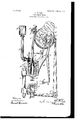
The accompanying drawing shows a vertical transverse section of my improved bydraulic press.
In the drawing, A represents the press-cylinder, which is supported by asuitable standard a.
B represents a hollow plunger, which is provided with an inwardly-projecting shoulder C vat its upper end and with a die D at its lower end. The hollow plunger is engaged by a piston E at the lower end of a pressure-spindle F. The spindle F ismoved in upward and downward direction by a crank G and a connecting-rod G, to which motion is imparted from the driving-shaft S.
The cylinder A is connected by a pipe H with a liquid-reservoir H, which is supported at a suitable distance above the press-cylinder A. The lower end of the pipe H communicates by a channel It with the interior of the press-cylinder A. The communicating channel can be' closed by a valve I, which is ordinarily held in open position by the tension of a helical spring that is interposed between the valve and the seat at the interior of the pipe H, the valve-spindle 6 extending through the lower end of the pipe H, so as to be engaged by an elbow-lever K, which is operated by cams m m on the shaft M, so that the valve I can be positively closed when the upper end of the elbow-lever K is engaged by one of the cams m m. The shaft M is operated from the driving-shaft S by means of the gear-wheels g To the shaft M are attached two additional cams Q and U, of which the cam Q, actuates the fulcrumed'lever P, which is connected at its lower end by a pivotlink at with the filling-box O, that is guided at the upper part of the mold R. The mold R is supported in the lower part of the standard a and provided with a vertically-reciprocating body 1*, that is actuated by a fulcrumed lever T and cam U, so that the stone or other article pressed in the mold is lifted clear of the same after the final or drying pressure has been given thereto.
My improved hydraulic press is operated in the following manner: When the parts are in the position shown in the drawing, the mold is supposed to be charged with the material to be pressed from the filling-box O. Three operations are performed by the operation of the driving-shaft S and the cams on the I O0 shaft M. The compressingmovements of the l the drawing, the water above the plunger in plunger B are each caused by the entrance of the spindle F into the cylinder and the resulting displacement of water between the cylinder and plunger to the extent of the entered volume of spindle. The operations are as follows, from the position of parts shown in the drawing: The shaft M, to which motion in the direction of the arrow is transmitted from shaft S by means of gears g and g, rotates all the cams, and the spindle F is given a downward movement by means of the connectingrod G and crank G, also actuated by shaft S. The plunger B descends with the spindle in the same relative position thereto as shown in the drawing by reason of the head of water above it. \Vhen the die D arrives upon the material in the mold R, a certain slight amount of compression is given to the material, owing to the weight of the plunger and the head of water above it, before the relative position.
of the spindle and plunger changes. It has been assumed that the space below the pistonhead E within the plunger B was filled with water before the start of descentin fact. that this space remains constantly filled with the fluid of compression-and that the weight of the same within the plunger is added to the weight of the plunger; but if, owing to tightness between the piston-head E and shoulder C, Water has not yet entered the plunger-space it does so and immediately fills said space, when, the resistance of the material in R having become sufficient to sustain the weight of the plunger and the head of water, the plunger remains stationary, with its die D upon the material, while the spindle F continues its descent and carries piston-head E downward away from shoulder C. Valve 1 is now closed by operation of cam m on elbow-lever K. This operation locks within the cylinder and plunger a certain quantity of water, which fills the same. The spindle F continues its descent into the cylinder, thereby displacing a bulk of water equal to the entering bulk of spindle. This displacement of water causes the plunger B to descend and compress the material in the mold R. The increased pressure in the fluid of compression aids the firm and tight seating of the Valve I during the operation. When the crank G passes the dead-center between its shaft S and the point of pivoting of the connecting-rod G to the spindle, it raises the connecting-rod, which withdraws the spindle F. The valve I is now permitted to be opened by retreat of cam m from lever K. A small quantity of water flows into the cylinder to fill the space left-upon the rise of the spindle and due to the fact that plunger B is now in a lower position than when the water was shut off. When upon the rise of the spindle the piston-head E arrives at the shoulder C, it engages therewith and then lifts the plunger back to its original position, as shown in the cylinder being displaced through valve I into the pipe H. On the second descent of the plunger the same descends, as in the first instance, in the shown position relatively to the spindle, owing to its own weight and the weight of water above and within the plunger, until its die D rests upon the partiallycompressed material in the mold R. Descent of the plunger is thus arrested at a point below that at which it was first arrested. The valve 1. is now closed by operation of cam on upon elbow-lever K, thereby locking in the space within the cylinder and plungeraquantity of water filling the same, and which quantity, owing to the further descent of the plunger before valve I was closed, is greater than was locked in on the first compression. The spindle F continues to descend and now displaces in the cylinder a quantity of water equal to the entering bulk of spindle. This bulk is less than on the first stroke, because of the lower position of the spindle at the time when the valve 1 was closed. The displacement of water causes the latter to force the plunger downwardly, thereby compressing the partially-compressed material in the mold R. The spindle F causes by its descent into the cylinder a descending of the plunger as long as there is no resistance to the latter. This is the non-active portion of the stroke. As soon as the resistance is exerted the plunger descends still farther, making its pressure-stroke. This stroke can be indicated by the equation: Pressure-stroke spindlespindle cross area plunger cross area' first pressure-stroke of the plunger the material is thereby compressed according to the following equation: Pressurestroke I (total spindle stroke non active stroke) cross-area plunger cross-area' stroke the material is again compressed according to the same formula; but as the nonactive stroke of the spindle is now greater than during the first stroke the pressurestroke is smaller than before. However, as the material has been compressed already by the first stroke it exerts now a much greater resistance than before, and in consequence the pressure of the pressure fluid is increased. The crank Gr having passed the dead-center, the parts rise, as previously described, after the first compression. During the second ascending motion of the spindle the plunger is withdrawn by the same, and simultaneously stroke During the During the second the finally pressed and dried block is raised Meantime the spindle F has descended again; but the plunger B cannot follow the same, as it is prevented from doing so by the fillingbox 0, which may be provided with projections for this purpose. closed, no pressure is generated in the presscylinder A. The spindle F ascends again, and With its next downward motion the operation before described is repeated.
This hydraulic press can be used for hydraulie pressure in which for some reason or other working strokes have to alternate with strokes which do not perform any work.
Having thus described my invention, I claim as new and desire to secure by Letters Patent- 1. In a hydraulic press, the combination, with a stationary press-cylinder, of a hollow plunger guided therein and provided with a compressing-die at its lower end, a verticallyreciprocating pressure-spindle provided with a collar at its lower end for engaging the upper end of the hollow plunger, a liquid-supply pipe connected with the press-cylinder, a valve normally open for opening and closing the connection between the press-cylinder and supply-pipe, and means for positively closing said valve at the proper time for producing the, final pressure, substantially as set forth.
As the valve I is not 2. In a hydraulic press, the combination, with a stationary press-cylinder, of a hollow plunger guided therein and provided with a compressing-die at its lower end, a verticallyreciprocating pressure-spindle provided with a collar at its'lower end for engaging the upper end of the hollow plunger, a liquid-supply pipe connected with the press-cylinder, a valve normally open for opening and closing the connection between the press-cylinder and supply-pipe, means for positively closing said valve at the proper time for producing the final pressure, a stationary mold vertically below the compressing-die, a bottom die," means for raising the bottom die when the final pressure has been imparted to the block, a fillingboX above the mold, and means for reciprocating said filling-box so as to move it in line with the mold and compressing-die for moving the block sidewise and producing the charging of the mold,substantially as set forth.
In testimony that I claim the foregoing as my invention I have signed my name in presence of two subscribing witnesses.
OTTO PHILIPP.
Witnesses:
PAUL GoErEL, C. P. GoEPEL.
Priority Applications (1)
| Application Number | Priority Date | Filing Date | Title |
|---|---|---|---|
| US12436502A US779800A (en) | 1902-09-22 | 1902-09-22 | Hydraulic press. |
Applications Claiming Priority (1)
| Application Number | Priority Date | Filing Date | Title |
|---|---|---|---|
| US12436502A US779800A (en) | 1902-09-22 | 1902-09-22 | Hydraulic press. |
Publications (1)
| Publication Number | Publication Date |
|---|---|
| US779800A true US779800A (en) | 1905-01-10 |
Family
ID=2848284
Family Applications (1)
| Application Number | Title | Priority Date | Filing Date |
|---|---|---|---|
| US12436502A Expired - Lifetime US779800A (en) | 1902-09-22 | 1902-09-22 | Hydraulic press. |
Country Status (1)
| Country | Link |
|---|---|
| US (1) | US779800A (en) |
Cited By (1)
| Publication number | Priority date | Publication date | Assignee | Title |
|---|---|---|---|---|
| US3920368A (en) * | 1974-01-24 | 1975-11-18 | Jerome H Lemelson | Toy molding press |
-
1902
- 1902-09-22 US US12436502A patent/US779800A/en not_active Expired - Lifetime
Cited By (1)
| Publication number | Priority date | Publication date | Assignee | Title |
|---|---|---|---|---|
| US3920368A (en) * | 1974-01-24 | 1975-11-18 | Jerome H Lemelson | Toy molding press |
Similar Documents
| Publication | Publication Date | Title |
|---|---|---|
| US2407855A (en) | Hydraulic press system | |
| US779800A (en) | Hydraulic press. | |
| US1071387A (en) | Percussive apparatus. | |
| US2491551A (en) | Hydraulic press | |
| US3143007A (en) | Hydraulic assist for press | |
| US3427856A (en) | High speed returning impact forming machine | |
| US2515323A (en) | Tamping machine | |
| US933010A (en) | Hydromechanical press. | |
| US2325119A (en) | Slug producing press | |
| US2267508A (en) | Hydraulic press | |
| US1955002A (en) | Fluid equalizer for compression machines | |
| US1241691A (en) | Hydraulic press. | |
| US2780836A (en) | Apparatus for applying low pressure advance and high pressure squeeze in the hydraulic operation of die casting dies | |
| US1429665A (en) | Hydraulic press | |
| US1270569A (en) | Press. | |
| US1269769A (en) | Hydraulic press. | |
| US1779093A (en) | Press | |
| US1003987A (en) | Hydraulic press. | |
| US1202616A (en) | Press. | |
| US1202619A (en) | Press. | |
| US553827A (en) | block | |
| US265229A (en) | hyatt | |
| US871078A (en) | Hydraulic press. | |
| US1202617A (en) | Press. | |
| US357124A (en) | g-ruson |