US7797859B2 - Snowplow and mount assembly - Google Patents
Snowplow and mount assembly Download PDFInfo
- Publication number
- US7797859B2 US7797859B2 US12/729,473 US72947310A US7797859B2 US 7797859 B2 US7797859 B2 US 7797859B2 US 72947310 A US72947310 A US 72947310A US 7797859 B2 US7797859 B2 US 7797859B2
- Authority
- US
- United States
- Prior art keywords
- frame
- snowplow
- latch
- mount
- jack stand
- Prior art date
- Legal status (The legal status is an assumption and is not a legal conclusion. Google has not performed a legal analysis and makes no representation as to the accuracy of the status listed.)
- Expired - Lifetime
Links
Images


Classifications
-
- E—FIXED CONSTRUCTIONS
- E01—CONSTRUCTION OF ROADS, RAILWAYS, OR BRIDGES
- E01H—STREET CLEANING; CLEANING OF PERMANENT WAYS; CLEANING BEACHES; DISPERSING OR PREVENTING FOG IN GENERAL CLEANING STREET OR RAILWAY FURNITURE OR TUNNEL WALLS
- E01H5/00—Removing snow or ice from roads or like surfaces; Grading or roughening snow or ice
- E01H5/04—Apparatus propelled by animal or engine power; Apparatus propelled by hand with driven dislodging or conveying levelling elements, conveying pneumatically for the dislodged material
- E01H5/06—Apparatus propelled by animal or engine power; Apparatus propelled by hand with driven dislodging or conveying levelling elements, conveying pneumatically for the dislodged material dislodging essentially by non-driven elements, e.g. scraper blades, snow-plough blades, scoop blades
- E01H5/065—Apparatus propelled by animal or engine power; Apparatus propelled by hand with driven dislodging or conveying levelling elements, conveying pneumatically for the dislodged material dislodging essentially by non-driven elements, e.g. scraper blades, snow-plough blades, scoop blades characterised by the form of the snow-plough blade, e.g. flexible, or by snow-plough blade accessories
- E01H5/066—Snow-plough blade accessories, e.g. deflector plates, skid shoes
Definitions
- This invention relates generally to snow removal equipment and, more particularly, to a snowplow and mount assembly for removably securing a snowplow to a vehicle.
- the vehicle operator may wish to remove the snow blade during times when the need for plowing snow arises infrequently or when the vehicle is used for purposes other than plowing snow.
- U.S. Pat. No. 5,353,530 hereby incorporated by reference herein as if fully set forth in its entirety.
- That patent discloses a mount frame having arms and a snowplow frame having receivers which receive the arms.
- the snowplow frame includes a lift frame and an A-frame pivoted to the lift frame.
- the receivers are formed as a part of the lift frame.
- the receivers carry latch pins which are spring biased toward a latching position yet which are lockable in an unlatched position.
- a jack stand is carried by the lift frame and is manually movable to and between an extended ground contacting and snowplow supporting position and a retracted ground noncontacting and snowplow nonsupporting position.
- the invention is a snowplow and mount assembly comprising a mount frame adapted to be secured to a vehicle, and a snowplow frame.
- One of the mount frame and the snowplow frame has first and second arms and the other of the mount frame and snowplow frame has first and second receivers, the first and second receivers receiving the first and second arms, respectfully.
- Respective ones of first and second latch pins removably secure the first and second arms in the first and second receivers.
- a latch lever is operably associated with the first and second latch pins and simultaneously actuates the latch pins to latched and unlatched positions.
- the assembly can further comprise a spring biasing each latch pin into the latched position and a pin extractor associated with each latch pin and actuatable by the latch lever to extract the latch pin from the latch arm against the bias of the spring.
- the extractor can include a cam which operably cams against the latch pin during the extraction thereof.
- the latch pin and respective extractor can be mounted in brackets mounted to the snowplow frame, the brackets guiding movement of the latch pin and extractor.
- the latch pins can travel transversely relative to a longitudinal axis of the assembly and the extractors can travel perpendicularly relative to the travel of the pins.
- the latch pin can include a cross pin therethrough which can compress the spring against a wall of the bracket as the cam cams against the cross pin.
- the cam surface can be a ramp.
- the latch lever can be pivotally connected to the snowplow frame, and the assembly can further include first and second linkages connected between the latch lever and the extractors.
- Each of the first and second linkages can include a linkage arm connected to the latch lever, and a linkage rod pivotally connected on a first end to the linkage arm and connected on a second end to the extractor.
- the latch lever can include a connecting rod extending transversely of the snowplow frame, with the first and second linkages being connected to the connecting rod.
- the first and second arms can be part of the mount frame and the first and second receivers can be part of the snowplow frame.
- the snowplow frame can comprise a lift frame and an A-frame pivotally connected to the lift frame on a rearward end of the A-frame.
- the assembly can further comprise a plow blade mounted on a forward end of the A-frame.
- the invention is a snowplow and mount assembly
- a mount frame adapted to be secured to a vehicle and a snowplow frame including a jack stand movable to and between an extended ground contacting and snowplow frame supporting position and a retracted ground noncontacting and snowplow frame nonsupporting position.
- a latch mechanism removably secures the snowplow frame to the mount frame.
- a latch lever actuates the latch mechanism to latched and unlatched positions, the latch lever operably freeing the jack stand for movement into the extended position when the latch mechanism is in the unlatched position and operably preventing jack stand movement maintaining the jack stand in the retracted position when the latch mechanism is in the latched position.
- the assembly can further comprise first and second jack stand locks, the first lock preventing relative movement of the jack stand relative to the snowplow frame when the jack stand is in the extended position and the second lock preventing relative movement of the jack stand relative to the snow plow frame when the jack stand is in the retracted position.
- the first jack stand lock can comprise a jack stand lock lever having an aperture therein through which a leg of the jack stand passes and a spring biasing an edge of the lock lever aperture into contact with the jack stand leg.
- the spring and lock lever normally prevent upward movement of the jack stand relative to the snowplow frame while permitting downward movement of the jack stand relative to the snowplow frame, whereas pivoting the lock lever against the bias of the spring frees the jack stand leg from the lock lever aperture edge permitting upward movement of the jack stand relative to the snowplow frame.
- the second jack stand lock can comprise a jack stand lock pin moveable into and out of an aperture in a leg of the jack stand and a spring biasing the lock pin toward the jack stand leg.
- the spring and lock pin normally prevent downward movement of the jack stand relative to the snowplow frame, whereas urging the lock pin against the bias of the spring frees the jack stand leg from the pin permitting downward movement of the jack stand relative to the snowplow frame.
- the jack stand can drop by gravity to the extended position when the jack stand leg is freed from the pin.
- the latch lever can include a cam operably connected thereto and the jack stand lock pin can be fixed to a cam follower which cooperates with the cam such that pivoting the latch lever to actuate the latch mechanism to the unlatched position urges the cam follower and hence the jack stand lock pin against the bias of the spring and away from the jack leg and out of the aperture thereof, whereas pivoting the latch lever to actuate the latch mechanism to the latched position permits the spring to bias the jack stand lock pin toward the jack stand leg and into the aperture thereof.
- the latch lever can include a connecting rod extending transversely of the snowplow frame, the cam can be a cylinder encircling the connecting rod affixed thereto and the cam follower can be a cylinder encircling the connecting rod and a slidable relative thereto.
- the cam cylinder and cam follower cylinder can have mating arcuate surfaces.
- a method of attaching a snowplow frame to a mount frame comprises providing a mount frame secured to a vehicle and a snowplow frame, one of the mount frame and the snowplow frame having first and second arms and the other of the mount frame and the snowplow frame having first and second receivers, the first and second receivers receiving the first and second arms, respectively, one of the mount frame and the snowplow frame having first and second latch pins, respective ones of which removably secure the first and second arms in the first and second receivers, and a lever operably associated with the first and second latch pins to simultaneously actuate the latch pins to a latched position, effecting relative movement between the mount frame and the snowplow frame so that the receivers receive the arms therein and actuating the lever to simultaneously actuate the pins to the latched position.
- a method of detaching a snowplow frame from a mount frame comprises providing a mount frame secured to a vehicle and a snowplow frame removably attached to the mount frame, one of the mount frame and the snowplow frame having first and second arms and the other of the mount frame and the snowplow frame having first and second receivers, the first and second receivers receiving the first and second arms, respectively, one of the mount frame and the snowplow frame having first and second latch pins, respective ones of which removably secure the first and second arms in the first and second receivers, and a lever operably associated with the first and second latch pins to simultaneously actuate the latch pins to an unlatched position, actuating the lever to simultaneously actuate the latch pins to the unlatched position and effecting relative movement between the mount frame and the snowplow frame so that the arms move out of the receivers.
- Another method of detaching a snowplow frame from a mount frame comprises providing a mount frame secured to a vehicle and a snowplow frame removably attached to the mount frame, the snowplow frame including a jack stand moveable to and between an extended ground contacting and snowplow frame supporting position and a refracted ground noncontacting and snowplow frame nonsupporting position, one of the mount frame and the snowplow frame having a latch mechanism which removably secures the snowplow frame to the mount frame and a lever which actuates the latch mechanism to an unlatched position and which frees the jack stand for movement into the extended position, actuating the lever to actuate the latch mechanism to the unlatched position and to free the jack stand to drop by gravity to the extended position, and effecting relative movement between the mount frame and the snowplow frame to separate the mount frame from the snowplow frame.
- the invention thus provides for the simultaneous latching and unlatching of the latch pins of a snowplow and for the automatic deployment of the snowplow jack stand during unlatching of the latch mechanism of the snowplow.
- FIG. 1 is a side view of the snowplow and mount assembly of the present invention
- FIG. 2 is a rear perspective view of the snowplow assembly of FIG. 1 ;
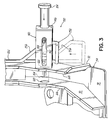
- FIG. 3 is an enlarged rear perspective view of the right hand receiver and its respective latch pin
- FIG. 5 is an enlarged rear perspective view of the jack stand lock which prevents relative movement of the jack stand relative to the snowplow frame when the jack stand is in the retracted position, shown unlocked;
- FIG. 6 is the jack stand lock of FIG. 5 , shown locked.
- Snowplow and mount assembly 10 comprises a snowplow assembly 12 and a mount assembly 14 .
- Snowplow assembly 12 can comprise a snowplow frame 20 having a lift frame 22 and an A-frame 24 pivoted to the lift frame 22 .
- A-frame 24 can be pivotally connected to lift frame 22 on a rearward end 26 of the A-frame 24 such as by bolt 28 for example.
- a forward end 30 of the A-frame 24 can carry a plow blade 32 .
- A-frame 24 can comprise left and right hand A-frame elements 34 , 36 , respectively, and a transverse element 38 interconnecting left and right hand A-frame elements 34 , 36 .
- the lower ends of elements 40 , 42 of lift frame 22 can include receivers 52 , 54 , respectively.
- Left hand receiver 52 can include sidewalls 56 , 58 having outwardly flared end portions 60 , 62 , respectively.
- a floor 64 can interconnect the sidewalls 56 , 58 .
- right hand receiver 54 can include sidewalls 66 , 68 having outwardly flared end portions 70 , 72 , respectively.
- a floor 74 can interconnect the sidewalls 66 , 68 .
- Lift frame 22 can include a lift arm 80 pivoted to transversely extending element 44 .
- a lift chain 82 and spring 84 can connect the lift arm 80 to the A frame 24 .
- a flexible wire rope cable can be used in place of the lift chain 82 .
- a lift cylinder 86 can be pivotally mounted to the lift arm 80 and transversely extending element 46 of the lift frame 22 , for raising and lowering lift arm 80 and hence A-frame 24 and plow blade 32 .
- Head light 88 can be mounted to transversely extending element 44 .
- mount assembly 14 can comprise a mount frame 90 adapted to be secured to a vehicle (phantom) having a pair of spaced arms 92 , 92 . Arms 92 , 92 are receivable in the receivers 52 , 54 of lift frame 22 . Each arm 92 includes a latch pin receiving hole 94 therein, the operation of which will be described below.
- a latch mechanism 100 can removably secure the snowplow frame 20 to the mount frame 90 .
- Latch mechanism 100 can comprise first and second latch pins 102 , 104 associated with receivers 52 , 54 , respectively.
- Latch pin 102 is operable to pass through hole 110 in sidewall 56 , hole 94 in arm 92 and hole 112 in sidewall 58 , when arm 92 is received within receiver 52 .
- latch pin 104 is operable to pass through hole 120 in sidewall 68 , hole 94 in the other arm 92 and hole 122 in sidewall 66 , when the other arm 92 is received within receiver 54 .
- a bracket 130 can be mounted to the outboard side of sidewall 56 of receiver 52 to carry latch pin 102 therein.
- a spring 132 can bias latch pin 102 into the latched position. More particularly, a cross pin 134 , for example roll pin, can be pressed through a hole (not shown) in latch pin 102 . Spring 132 can be disposed between cross pin 134 and an inboard surface of end plate 136 of bracket 130 .
- a bracket 140 can be mounted to the outboard side of sidewall 68 of receiver 54 to carry latch pin 104 therein.
- a spring 142 can bias latch pin 104 into the latched position. More particularly, a cross pin 144 , for example roll pin, can be pressed through a hole (not shown) in latch pin 104 . Spring 142 can be disposed between cross pin 144 and an inboard surface of end plate 146 of bracket 140 .
- receivers 52 , 54 can each include a pin extractor 150 , 152 associated respectively therewith.
- Each extractor 150 , 152 can include a cam 154 , 156 , respectively, which can be in the form of a ramp, to cam against cross pins 134 , 142 , respectively, and hence operably against latch pins 102 , 104 , respectively, the operation of which will be described below.
- a latch lever 160 can be operably associated with the first and second latch pins 102 , 104 for simultaneously actuating the latch pins 102 , 104 to latched and unlatched positions.
- Latch lever 160 can include a connecting rod 162 extending transversely of the lift frame 22 and pivotally connected thereto.
- First and second linkage mechanisms 164 , 166 can be connected to latch lever 160 for actuating the extractors 150 , 152 associated with latch pins 102 , 104 , respectively.
- Linkage 164 can include a linkage arm 170 connected to connecting rod 162 and a linkage rod 172 pivotally connected on a first end to the linkage arm 170 and connected on a second end to the extractor 150 .
- linkage 166 can include a linkage arm 180 connected to connecting rod 162 and a linkage rod 182 pivotally connected on a first end to the linkage arm 180 and connected on a second end to extractor 152 .
- latch lever 160 In use, rotation of latch lever 160 counterclockwise (as viewed from the left hand side shown in FIG. 1 ) from the up position (solid, FIG. 1 ) to the down position (phantom, FIG. 1 ), as when detaching the snowplow assembly 12 from the mount assembly 14 , actuates linkages 164 , 166 to pull extractors 150 , 152 upwardly and frontwardly.
- the ramped cams 154 , 156 of the extractors 150 , 152 force cross pins 134 , 144 laterally outwardly against the bias of springs 132 , 142 thus moving latch pins 102 , 104 laterally outwardly to their unlatched positions.
- the ramped cams 154 , 156 of the extractors 150 , 152 permit cross pins 134 , 144 to move laterally inwardly via the bias of springs 132 , 142 thus moving latch pins 102 , 104 laterally inwardly to their latched positions.
- a jack stand 190 can be slidably mounted to lift frame 22 .
- Jack stand 190 can include a leg 192 and a foot 194 .
- Jack stand 190 is moveable to and between an extended ground contacting and snowplow frame supporting position (solid, FIG. 1 ) and a retracted ground noncontacting and snowplow frame nonsupporting position (phantom, FIG. 1 ; FIG. 2 ).
- First 200 and second 202 jack stand locks can be provided to prevent relative movement of the jack stand 190 relative to the lift frame 22 when the jack stand 190 is in the extended position, and to prevent relative movement of the jack stand 190 relative to the lift frame 22 when the jack stand 190 is in the retracted position, respectively.
- First jack stand lock 200 can include a lock lever 210 pivoted to a wall 212 of a bracket 214 mounted to top plate 48 of transverse element 46 of lift frame 22 .
- Lock lever 210 can be pivoted to wall 212 as by passing an end 216 of lever 210 through aperture 218 in wall 212 .
- Lock lever 210 can have an aperture 220 therein through which jack stand leg 192 passes, and a spring 222 positioned between lock lever 210 and top plate 48 biasing edges 224 , 226 of aperture 220 into contact with jack stand leg 192 .
- Lock lever 210 and bracket 214 are sized and configured so as to prevent inadvertent actuation thereof when snowplow assembly 12 is detached from mount assembly 14 .
- Spring 222 and lock lever 210 normally prevent upward movement of jack stand leg 192 relative to lift frame 22 while at the same time freely permitting downward movement of jack stand leg 192 relative to the lift frame 22 . Pivoting lock lever 210 downwardly ( FIG. 4 ) frees jack stand leg 192 of edges 224 , 226 of lock lever aperture 220 thereby permitting upward movement of the jack stand leg 192 relative to the lift frame 22 .
- Second jack stand lock 202 can include a lock pin 240 moveable into and out of an aperture 242 in jack stand leg 192 and a spring 244 biasing lock pin 240 toward the jack stand leg 192 .
- the spring 244 and lock pin 240 normally prevent downward movement of the jack stand 192 relative to the lift frame 22 , whereas urging the lock pin 240 against the bias of the spring 244 frees the jack stand leg 192 from the pin 240 permitting downward movement of the jack stand 190 relative to the lift frame 22 .
- the jack stand 190 can drop by gravity to the extended position when the jack stand leg 192 is freed from pin 240 .
- the second jack stand lock 202 can further include a cam 260 connected to connecting rod 162 and a cam follower 262 having fixed thereto the lock pin 240 .
- Cam 260 can be in the form of a cylinder encircling connecting rod 162 and fixed thereto and cam follower 262 can be in the form of a cylinder encircling connecting rod 162 and slidable relative thereto.
- Cam 260 and cam follower 262 can have mating arcuate, for example helix, cam surfaces 264 , 266 , respectively.
- Cam follower 262 and hence lock pin 240 can be spring biased toward jack stand leg 192 via spring 244 positioned between cam follower 262 and a plate 272 connected between plates 48 and 50 .
- Cam follower 262 and hence pin 240 can be prevented from rotating via U-bracket 274 fixed to plate 50 and having arms 276 , 276 with holes 278 , 278 therein through which pin 240 passes.
- cam 260 is fixedly secured to connecting rod 162 and as such will rotate with connecting rod 162 as latch lever 160 is rotated.
- the spring rates of springs 132 , 142 , 222 and 244 , and the geometries of their associated mechanisms, can be selected so that jack stand 190 falls by gravity to the ground during the first portion of the arc traversed by lever 160 in moving lever 160 from the up position toward the down position, while latch pins 102 , 104 remain latched. Then, as lever 160 is moved the remaining portion of the arc to the down position, latch pins 102 , 104 are moved to their unlatched positions.
- latch lever 160 As described above rotation of latch lever 160 clockwise from the down position to the up position, as when attaching snowplow assembly 12 to mount assembly 14 , actuates linkages 164 , 166 to move latch pins 102 , 104 to their latched positions.
- jack stand lock lever 210 can be pressed downwardly freeing jack stand leg 192 .
- Jack stand leg 192 is then manually pulled upwardly until jack stand lock pin 240 is seated in aperture 242 in jack stand leg 192 .
- a force should be applied to the lift frame 22 , such as on transverse element 44 , in the direction of the mount assembly 14 as latch lever 160 is rotated.
- Such movement facilitates alignment of the latch pins 102 , 104 with the holes 94 in the arms 92 .
- tension spring 84 extended during normal operation of snowplow assembly 12 , retracts when snowplow assembly 12 is parked, blade 32 is dropped to the ground and the hydraulic control is placed in the “float” condition releasing the pressure in the lift cylinder 86 , pulling lift arm 80 downwardly to its fully collapsed positioned and creating slack in the lift chain 82 .
- Latch lever 160 and linkage mechanisms 164 , 166 are designed so that the mechanical advantage produced thereby is insufficient to unlatch “loaded” latch pins 102 , 104 , thus preventing the snowplow assembly 12 from “collapsing in a heap.”
- initial rotation of latch lever 160 permits jack stand 190 to fall by gravity and support the snowplow assembly 12 .
- Further rotation of latch lever 160 to retract latch pins 102 , 104 is not possible until lift frame 22 is pivoted relative to A-frame 24 and toward mount frame 90 to unload latch pins 102 , 104 .
- Jack stand 190 and jack stand foot 194 are sized, configured and located to permit such pivoting of lift frame 22 relative to A-frame 24 without causing instability of the snowplow assembly 12 during such pivoting.
Landscapes
- Engineering & Computer Science (AREA)
- Architecture (AREA)
- Civil Engineering (AREA)
- Structural Engineering (AREA)
- Cleaning Of Streets, Tracks, Or Beaches (AREA)
Abstract
Description
Claims (4)
Priority Applications (1)
| Application Number | Priority Date | Filing Date | Title |
|---|---|---|---|
| US12/729,473 US7797859B2 (en) | 2001-06-11 | 2010-03-23 | Snowplow and mount assembly |
Applications Claiming Priority (4)
| Application Number | Priority Date | Filing Date | Title |
|---|---|---|---|
| US09/878,744 US6944978B2 (en) | 2001-06-11 | 2001-06-11 | Snowplow and mount assembly |
| US11/231,072 US7430821B2 (en) | 2001-06-11 | 2005-09-20 | Snowplow and mount assembly |
| US12/246,671 US7681334B2 (en) | 2001-06-11 | 2008-10-07 | Snowplow and mount assembly |
| US12/729,473 US7797859B2 (en) | 2001-06-11 | 2010-03-23 | Snowplow and mount assembly |
Related Parent Applications (1)
| Application Number | Title | Priority Date | Filing Date |
|---|---|---|---|
| US12/246,671 Division US7681334B2 (en) | 2001-06-11 | 2008-10-07 | Snowplow and mount assembly |
Publications (2)
| Publication Number | Publication Date |
|---|---|
| US20100175281A1 US20100175281A1 (en) | 2010-07-15 |
| US7797859B2 true US7797859B2 (en) | 2010-09-21 |
Family
ID=25372742
Family Applications (4)
| Application Number | Title | Priority Date | Filing Date |
|---|---|---|---|
| US09/878,744 Expired - Lifetime US6944978B2 (en) | 2001-06-11 | 2001-06-11 | Snowplow and mount assembly |
| US11/231,072 Active US7430821B2 (en) | 2001-06-11 | 2005-09-20 | Snowplow and mount assembly |
| US12/246,671 Expired - Lifetime US7681334B2 (en) | 2001-06-11 | 2008-10-07 | Snowplow and mount assembly |
| US12/729,473 Expired - Lifetime US7797859B2 (en) | 2001-06-11 | 2010-03-23 | Snowplow and mount assembly |
Family Applications Before (3)
| Application Number | Title | Priority Date | Filing Date |
|---|---|---|---|
| US09/878,744 Expired - Lifetime US6944978B2 (en) | 2001-06-11 | 2001-06-11 | Snowplow and mount assembly |
| US11/231,072 Active US7430821B2 (en) | 2001-06-11 | 2005-09-20 | Snowplow and mount assembly |
| US12/246,671 Expired - Lifetime US7681334B2 (en) | 2001-06-11 | 2008-10-07 | Snowplow and mount assembly |
Country Status (2)
| Country | Link |
|---|---|
| US (4) | US6944978B2 (en) |
| CA (2) | CA2356036C (en) |
Cited By (5)
| Publication number | Priority date | Publication date | Assignee | Title |
|---|---|---|---|---|
| US8967286B2 (en) | 2013-03-04 | 2015-03-03 | Kois Brothers Equipment Co., Inc. | Lateral mount for vehicle mounted implement |
| US9869067B2 (en) | 2014-11-13 | 2018-01-16 | Douglas Dynamics, L.L.C. | Snow plow and mount assembly |
| USD844673S1 (en) | 2017-12-09 | 2019-04-02 | Samasz Sp. Z O.O. | Snowplow |
| US11248354B2 (en) | 2020-03-12 | 2022-02-15 | Ricky A. Weihl | Plow assembly |
| US11466417B2 (en) | 2020-03-12 | 2022-10-11 | Ricky A. Weihl | Plow assembly |
Families Citing this family (22)
| Publication number | Priority date | Publication date | Assignee | Title |
|---|---|---|---|---|
| US6944978B2 (en) * | 2001-06-11 | 2005-09-20 | Douglas Dynamics, Llc | Snowplow and mount assembly |
| US6874582B2 (en) * | 2002-09-06 | 2005-04-05 | Henderson Manufacturing Company | Plow hitch for vehicle |
| US7693856B2 (en) * | 2004-06-25 | 2010-04-06 | Apple Inc. | Methods and systems for managing data |
| CA2576954A1 (en) * | 2005-11-08 | 2006-09-18 | Soucy International Inc. | Atv plow support frame assembly with quick locking system and method for installing same |
| US7526883B2 (en) * | 2006-11-21 | 2009-05-05 | Sp Fabricators, Llc | Plow hitch with cam locking blocks |
| US7574820B2 (en) * | 2006-11-21 | 2009-08-18 | Sp Fabricators, Llc | Jack stand for plow hitch |
| US7841110B2 (en) * | 2008-06-17 | 2010-11-30 | Sno-Way International, Inc. | Plow quick connect/disconnect hitch mechanism |
| US7513069B1 (en) | 2008-06-17 | 2009-04-07 | Sno-Way International, Inc. | Snow plow jack stand |
| US7934328B2 (en) | 2008-06-17 | 2011-05-03 | Sno-Way International, Inc. | V-plow cutting edge interface |
| US8061063B2 (en) | 2008-06-17 | 2011-11-22 | Sno-Way International, Inc. | Plow wing blade |
| US8832974B2 (en) | 2008-06-17 | 2014-09-16 | Sno-Way International, Inc. | V-plow |
| US20090307943A1 (en) * | 2008-06-17 | 2009-12-17 | Buckbee Mark D | Snow plow blade including nut retaining plate |
| US20100101119A1 (en) * | 2008-10-27 | 2010-04-29 | Andrew Roberts | Quick-attach secondary lift mechanism for snowplows |
| US8689898B2 (en) * | 2010-01-09 | 2014-04-08 | Brian Anthony Benesch | Removable loader for all-terrain and utility-terrain vehicles |
| US8707537B2 (en) * | 2010-12-27 | 2014-04-29 | Donald E. Clark | System and method for securing detachable construction equipment |
| US8732990B1 (en) | 2011-04-15 | 2014-05-27 | Aaron Danreuther | Wing lock for side-mounted snow plow |
| US8763715B2 (en) * | 2011-05-11 | 2014-07-01 | Ralph L. Osgood, Inc. | Quick-connect plow hitch |
| KR101873056B1 (en) * | 2011-09-20 | 2018-07-02 | 삼성전자주식회사 | Device and method for performing application in wireless terminal |
| CA2886826C (en) * | 2015-04-01 | 2021-03-02 | Soucy International Inc | Self-detaching support frame system for an implement and method for using the same |
| CN105183149B (en) * | 2015-08-12 | 2018-02-27 | 京东方科技集团股份有限公司 | Distance sensing substrate, display device, display system and method for adjusting resolution |
| EP3352553A4 (en) * | 2015-09-25 | 2019-04-24 | Meyer Products, LLC. | Expandable containment plow |
| CN105133527B (en) * | 2015-09-30 | 2017-03-22 | 贵州远方生态环保科技股份有限公司 | Road sweeper capable of reducing damage rate of tray brush and increasing cleaning ability |
Citations (26)
| Publication number | Priority date | Publication date | Assignee | Title |
|---|---|---|---|---|
| US3410008A (en) | 1965-01-13 | 1968-11-12 | Burch Corp | Snow plow coupling mechanism |
| US3410006A (en) | 1965-03-24 | 1968-11-12 | Vogel Raimund | Reinforced footwear |
| US3987562A (en) | 1975-06-02 | 1976-10-26 | American Equipment Corporation | Quick connect snow plow implement |
| US4096652A (en) | 1976-11-08 | 1978-06-27 | H. K. Nuttall Equipment Co., Inc. | Retractable snowplow wing and mounting therefor |
| US4924610A (en) * | 1989-05-22 | 1990-05-15 | Sodemann Wayne N | Apparatus for roadway snow plow attachment |
| US4962599A (en) * | 1990-04-12 | 1990-10-16 | Dsp, Inc. | Quick connect-disconnect coupling for snow plow |
| US5014452A (en) * | 1989-02-21 | 1991-05-14 | Berghefer Ray A | Plow mounting apparatus |
| US5031927A (en) * | 1989-07-14 | 1991-07-16 | Frenette Albert E | Semi-automatic attach device for mounting snowplows |
| US5050321A (en) * | 1990-10-23 | 1991-09-24 | Evans Roy C | Snow plow hitch pin assisting means |
| US5111603A (en) * | 1990-08-29 | 1992-05-12 | Knowlton Leland P | Coupling for a snow plow |
| US5195261A (en) * | 1992-04-16 | 1993-03-23 | Bertrand Vachon | Quick-hitching device for detachably mounting an attachment to a vehicle frame |
| US5353530A (en) * | 1992-09-02 | 1994-10-11 | Douglas Dynamics, Inc. | Quick mounting snow plow assembly |
| US5485690A (en) * | 1994-01-18 | 1996-01-23 | Macqueen; James P. | Lightweight modular snowplow for quick attachment to and simple, economical operation for small vehicle |
| US5568694A (en) | 1993-12-15 | 1996-10-29 | M. J. Electric, Inc. | Behind the bumper, quick attachment system and mechanism for truck mounted snow plows |
| US5815956A (en) | 1996-04-30 | 1998-10-06 | Curtis International , Inc. | Vehicle mounting assembly for a snow plow with hidden actuator drive |
| US6012240A (en) * | 1997-11-26 | 2000-01-11 | Douglas Dynamics, L.L.C. | Vehicle mountable snowplow |
| US6035944A (en) | 1998-05-27 | 2000-03-14 | M. J. Electric, Inc. | Hinged plow attachment for wheeled and tracked vehicles |
| US6088937A (en) | 1998-03-05 | 2000-07-18 | Diclementi; James Anthony | Vehicle plow suspension system |
| US6108946A (en) | 1998-05-28 | 2000-08-29 | M.J. Electric, Inc. | Plowed material catcher for V-blade snowplow |
| US6134814A (en) | 1998-05-28 | 2000-10-24 | M. J. Electric, Inc. | Hydraulic locking cylinder for plow blades |
| US6145222A (en) | 1998-08-14 | 2000-11-14 | Curtis International, Inc. | Vehicle hitch mount assembly for a snow plow |
| US6209231B1 (en) | 1998-08-14 | 2001-04-03 | Curtis International, Inc. | Vehicle hitch mount assembly for a snow plow |
| US6354024B1 (en) | 1999-11-29 | 2002-03-12 | The Louis Berkman Company | Snowplow mount |
| US6526677B1 (en) | 2000-10-06 | 2003-03-04 | Douglas Dynamics, L.L.C. | Snowplow mounting assembly |
| US6874582B2 (en) | 2002-09-06 | 2005-04-05 | Henderson Manufacturing Company | Plow hitch for vehicle |
| US6944978B2 (en) | 2001-06-11 | 2005-09-20 | Douglas Dynamics, Llc | Snowplow and mount assembly |
Family Cites Families (1)
| Publication number | Priority date | Publication date | Assignee | Title |
|---|---|---|---|---|
| US5465690A (en) * | 1994-04-12 | 1995-11-14 | A. Ahlstrom Corporation | Method of purifying gases containing nitrogen oxides and an apparatus for purifying gases in a steam generation boiler |
-
2001
- 2001-06-11 US US09/878,744 patent/US6944978B2/en not_active Expired - Lifetime
- 2001-08-29 CA CA002356036A patent/CA2356036C/en not_active Expired - Lifetime
- 2001-08-29 CA CA2632102A patent/CA2632102C/en not_active Expired - Fee Related
-
2005
- 2005-09-20 US US11/231,072 patent/US7430821B2/en active Active
-
2008
- 2008-10-07 US US12/246,671 patent/US7681334B2/en not_active Expired - Lifetime
-
2010
- 2010-03-23 US US12/729,473 patent/US7797859B2/en not_active Expired - Lifetime
Patent Citations (29)
| Publication number | Priority date | Publication date | Assignee | Title |
|---|---|---|---|---|
| US3410008A (en) | 1965-01-13 | 1968-11-12 | Burch Corp | Snow plow coupling mechanism |
| US3410006A (en) | 1965-03-24 | 1968-11-12 | Vogel Raimund | Reinforced footwear |
| US3987562A (en) | 1975-06-02 | 1976-10-26 | American Equipment Corporation | Quick connect snow plow implement |
| US4096652A (en) | 1976-11-08 | 1978-06-27 | H. K. Nuttall Equipment Co., Inc. | Retractable snowplow wing and mounting therefor |
| US5014452A (en) * | 1989-02-21 | 1991-05-14 | Berghefer Ray A | Plow mounting apparatus |
| US4924610A (en) * | 1989-05-22 | 1990-05-15 | Sodemann Wayne N | Apparatus for roadway snow plow attachment |
| US5031927A (en) * | 1989-07-14 | 1991-07-16 | Frenette Albert E | Semi-automatic attach device for mounting snowplows |
| US4962599A (en) * | 1990-04-12 | 1990-10-16 | Dsp, Inc. | Quick connect-disconnect coupling for snow plow |
| US5111603A (en) * | 1990-08-29 | 1992-05-12 | Knowlton Leland P | Coupling for a snow plow |
| US5050321A (en) * | 1990-10-23 | 1991-09-24 | Evans Roy C | Snow plow hitch pin assisting means |
| US5195261A (en) * | 1992-04-16 | 1993-03-23 | Bertrand Vachon | Quick-hitching device for detachably mounting an attachment to a vehicle frame |
| US5353530A (en) * | 1992-09-02 | 1994-10-11 | Douglas Dynamics, Inc. | Quick mounting snow plow assembly |
| US5568694A (en) | 1993-12-15 | 1996-10-29 | M. J. Electric, Inc. | Behind the bumper, quick attachment system and mechanism for truck mounted snow plows |
| US5485690A (en) * | 1994-01-18 | 1996-01-23 | Macqueen; James P. | Lightweight modular snowplow for quick attachment to and simple, economical operation for small vehicle |
| US5815956A (en) | 1996-04-30 | 1998-10-06 | Curtis International , Inc. | Vehicle mounting assembly for a snow plow with hidden actuator drive |
| US6012240A (en) * | 1997-11-26 | 2000-01-11 | Douglas Dynamics, L.L.C. | Vehicle mountable snowplow |
| US6088937A (en) | 1998-03-05 | 2000-07-18 | Diclementi; James Anthony | Vehicle plow suspension system |
| US6035944A (en) | 1998-05-27 | 2000-03-14 | M. J. Electric, Inc. | Hinged plow attachment for wheeled and tracked vehicles |
| US6108946A (en) | 1998-05-28 | 2000-08-29 | M.J. Electric, Inc. | Plowed material catcher for V-blade snowplow |
| US6134814A (en) | 1998-05-28 | 2000-10-24 | M. J. Electric, Inc. | Hydraulic locking cylinder for plow blades |
| US6209231B1 (en) | 1998-08-14 | 2001-04-03 | Curtis International, Inc. | Vehicle hitch mount assembly for a snow plow |
| US6145222A (en) | 1998-08-14 | 2000-11-14 | Curtis International, Inc. | Vehicle hitch mount assembly for a snow plow |
| US6408546B2 (en) | 1998-08-14 | 2002-06-25 | Curtis International, Inc. | Vehicle hitch mount assembly for a snow plow |
| US6354024B1 (en) | 1999-11-29 | 2002-03-12 | The Louis Berkman Company | Snowplow mount |
| US6526677B1 (en) | 2000-10-06 | 2003-03-04 | Douglas Dynamics, L.L.C. | Snowplow mounting assembly |
| US6944978B2 (en) | 2001-06-11 | 2005-09-20 | Douglas Dynamics, Llc | Snowplow and mount assembly |
| US7430821B2 (en) | 2001-06-11 | 2008-10-07 | Douglas Dynamics, L.L.C. | Snowplow and mount assembly |
| US7681334B2 (en) | 2001-06-11 | 2010-03-23 | Batesville Services, Inc. | Snowplow and mount assembly |
| US6874582B2 (en) | 2002-09-06 | 2005-04-05 | Henderson Manufacturing Company | Plow hitch for vehicle |
Cited By (10)
| Publication number | Priority date | Publication date | Assignee | Title |
|---|---|---|---|---|
| US8967286B2 (en) | 2013-03-04 | 2015-03-03 | Kois Brothers Equipment Co., Inc. | Lateral mount for vehicle mounted implement |
| US9869067B2 (en) | 2014-11-13 | 2018-01-16 | Douglas Dynamics, L.L.C. | Snow plow and mount assembly |
| US10900183B2 (en) | 2014-11-13 | 2021-01-26 | Douglas Dynamics, L.L.C. | Snow plow and mount assembly |
| US11332899B2 (en) | 2014-11-13 | 2022-05-17 | Douglas Dynamics, L.L.C. | Snow plow and mount assembly |
| US11427978B2 (en) | 2014-11-13 | 2022-08-30 | Douglas Dynamics, L.L.C. | Snow plow and mount assembly |
| USD844673S1 (en) | 2017-12-09 | 2019-04-02 | Samasz Sp. Z O.O. | Snowplow |
| US11248354B2 (en) | 2020-03-12 | 2022-02-15 | Ricky A. Weihl | Plow assembly |
| US11466416B2 (en) | 2020-03-12 | 2022-10-11 | Ricky A. Weihl | Plow assembly |
| US11466417B2 (en) | 2020-03-12 | 2022-10-11 | Ricky A. Weihl | Plow assembly |
| US11591761B2 (en) | 2020-03-12 | 2023-02-28 | Ricky A. Weihl | Plow assembly |
Also Published As
| Publication number | Publication date |
|---|---|
| US20060010722A1 (en) | 2006-01-19 |
| US20100175281A1 (en) | 2010-07-15 |
| US6944978B2 (en) | 2005-09-20 |
| CA2356036C (en) | 2010-02-02 |
| US7681334B2 (en) | 2010-03-23 |
| US7430821B2 (en) | 2008-10-07 |
| CA2356036A1 (en) | 2002-12-11 |
| US20090031592A1 (en) | 2009-02-05 |
| CA2632102A1 (en) | 2002-12-11 |
| US20020184796A1 (en) | 2002-12-12 |
| CA2632102C (en) | 2010-10-12 |
Similar Documents
| Publication | Publication Date | Title |
|---|---|---|
| US7797859B2 (en) | Snowplow and mount assembly | |
| US6928757B2 (en) | Snowplow mounting assembly | |
| US4986722A (en) | Mounting structure for a loader attachment | |
| US4345870A (en) | Quick attach loader | |
| US6276076B1 (en) | Plow hitch assembly for vehicles | |
| US7526883B2 (en) | Plow hitch with cam locking blocks | |
| CA2361592C (en) | Trailer with non-tilting moveable bed | |
| JPS63167818A (en) | Method and apparatus for mounting and detaching loader with respect to tractor | |
| US8162586B2 (en) | Parking stand | |
| US5183235A (en) | Apparatus for aligning and releasing a two-part jack system | |
| US3984016A (en) | Attachment mounting for end loader | |
| US3181891A (en) | Support stand | |
| US6427430B1 (en) | Pedal lift system for lawn tractor mower deck | |
| US5004398A (en) | Backhoe mounting device for a skid steer loader | |
| US20200047690A1 (en) | Self-detaching support frame system for an implement and method for using the same | |
| CA1295285C (en) | Latching mechanism for a loader | |
| US20200283977A1 (en) | Snow plow mounting assembly | |
| CN112983309B (en) | Automatic pipe column conveying device | |
| CA3073426A1 (en) | Snow plow mounting assembly | |
| JP4098065B2 (en) | Working unit attachment / detachment device for work equipment | |
| JP2558079B2 (en) | How to connect an agricultural implement to a tractor |
Legal Events
| Date | Code | Title | Description |
|---|---|---|---|
| STCF | Information on status: patent grant |
Free format text: PATENTED CASE |
|
| AS | Assignment |
Owner name: JPMORGAN CHASE BANK, N.A., WISCONSIN Free format text: FIRST LIEN PATENT SECURITY AGREEMENT;ASSIGNORS:DOUGLAS DYNAMICS, INC.;DOUGLAS DYNAMICS, L.L.C.;DOUGLAS DYNAMICS FINANCE COMPANY;AND OTHERS;REEL/FRAME:026165/0423 Effective date: 20110418 |
|
| FPAY | Fee payment |
Year of fee payment: 4 |
|
| MAFP | Maintenance fee payment |
Free format text: PAYMENT OF MAINTENANCE FEE, 8TH YEAR, LARGE ENTITY (ORIGINAL EVENT CODE: M1552) Year of fee payment: 8 |
|
| AS | Assignment |
Owner name: JPMORGAN CHASE BANK, N.A,, AS COLLATERAL AGENT, ILLINOIS Free format text: PATENT SECURITY AGREEMENT (ABL);ASSIGNORS:DOUGLAS DYNAMICS, L.L.C.;TRYNEX INTERNATIONAL LLC;HENDERSON PRODUCTS, INC.;REEL/FRAME:053168/0529 Effective date: 20200708 |
|
| AS | Assignment |
Owner name: DOUGLAS DYNAMICS, L.L.C., WISCONSIN Free format text: RELEASE OF SECURITY INTEREST IN PATENTS PREVIOUSLY RECORDED AT REEL/FRAME (053168/0529);ASSIGNOR:JPMORGAN CHASE BANK, N.A., AS COLLATERAL AGENT;REEL/FRAME:056676/0584 Effective date: 20210609 Owner name: TRYNEX INTERNATIONAL LLC, MICHIGAN Free format text: RELEASE OF SECURITY INTEREST IN PATENTS PREVIOUSLY RECORDED AT REEL/FRAME (053168/0529);ASSIGNOR:JPMORGAN CHASE BANK, N.A., AS COLLATERAL AGENT;REEL/FRAME:056676/0584 Effective date: 20210609 Owner name: HENDERSON PRODUCTS, INC., WISCONSIN Free format text: RELEASE OF SECURITY INTEREST IN PATENTS PREVIOUSLY RECORDED AT REEL/FRAME (053168/0529);ASSIGNOR:JPMORGAN CHASE BANK, N.A., AS COLLATERAL AGENT;REEL/FRAME:056676/0584 Effective date: 20210609 |
|
| AS | Assignment |
Owner name: JPMORGAN CHASE BANK, N.A., AS ADMINISTRATIVE AGENT, ILLINOIS Free format text: SECURITY INTEREST;ASSIGNORS:DOUGLAS DYNAMICS, L.L.C.;TRYNEX INTERNATIONAL LLC;HENDERSON PRODUCTS, INC.;AND OTHERS;REEL/FRAME:056538/0901 Effective date: 20210609 Owner name: DOUGLAS DYNAMICS, L.L.C., WISCONSIN Free format text: RELEASE OF SECURITY INTEREST IN PATENTS PREVIOUSLY RECORDED AT REEL/FRAME (026165/0423);ASSIGNOR:JPMORGAN CHASE BANK, N.A., AS COLLATERAL AGENT;REEL/FRAME:056540/0199 Effective date: 20210609 Owner name: DOUGLAS DYNAMICS, INC., WISCONSIN Free format text: RELEASE OF SECURITY INTEREST IN PATENTS PREVIOUSLY RECORDED AT REEL/FRAME (026165/0423);ASSIGNOR:JPMORGAN CHASE BANK, N.A., AS COLLATERAL AGENT;REEL/FRAME:056540/0199 Effective date: 20210609 Owner name: DOUGLAS DYNAMICS FINANCE COMPANY, WISCONSIN Free format text: RELEASE OF SECURITY INTEREST IN PATENTS PREVIOUSLY RECORDED AT REEL/FRAME (026165/0423);ASSIGNOR:JPMORGAN CHASE BANK, N.A., AS COLLATERAL AGENT;REEL/FRAME:056540/0199 Effective date: 20210609 Owner name: FISHER, LLC, MAINE Free format text: RELEASE OF SECURITY INTEREST IN PATENTS PREVIOUSLY RECORDED AT REEL/FRAME (026165/0423);ASSIGNOR:JPMORGAN CHASE BANK, N.A., AS COLLATERAL AGENT;REEL/FRAME:056540/0199 Effective date: 20210609 |
|
| MAFP | Maintenance fee payment |
Free format text: PAYMENT OF MAINTENANCE FEE, 12TH YEAR, LARGE ENTITY (ORIGINAL EVENT CODE: M1553); ENTITY STATUS OF PATENT OWNER: LARGE ENTITY Year of fee payment: 12 |