US779594A - Lock. - Google Patents
Lock. Download PDFInfo
- Publication number
- US779594A US779594A US1904187715A US779594A US 779594 A US779594 A US 779594A US 1904187715 A US1904187715 A US 1904187715A US 779594 A US779594 A US 779594A
- Authority
- US
- United States
- Prior art keywords
- bolt
- lock
- tumbler
- casing
- head
- Prior art date
- Legal status (The legal status is an assumption and is not a legal conclusion. Google has not performed a legal analysis and makes no representation as to the accuracy of the status listed.)
- Expired - Lifetime
Links
Images
Classifications
-
- B—PERFORMING OPERATIONS; TRANSPORTING
- B65—CONVEYING; PACKING; STORING; HANDLING THIN OR FILAMENTARY MATERIAL
- B65D—CONTAINERS FOR STORAGE OR TRANSPORT OF ARTICLES OR MATERIALS, e.g. BAGS, BARRELS, BOTTLES, BOXES, CANS, CARTONS, CRATES, DRUMS, JARS, TANKS, HOPPERS, FORWARDING CONTAINERS; ACCESSORIES, CLOSURES, OR FITTINGS THEREFOR; PACKAGING ELEMENTS; PACKAGES
- B65D77/00—Packages formed by enclosing articles or materials in preformed containers, e.g. boxes, cartons, sacks or bags
- B65D77/10—Container closures formed after filling
- B65D77/16—Container closures formed after filling by collapsing and twisting mouth portion
- B65D77/18—Container closures formed after filling by collapsing and twisting mouth portion and securing by a deformable clip or binder
- B65D77/185—Container closures formed after filling by collapsing and twisting mouth portion and securing by a deformable clip or binder with means for discouraging or for indicating unauthorised opening or removal
-
- Y—GENERAL TAGGING OF NEW TECHNOLOGICAL DEVELOPMENTS; GENERAL TAGGING OF CROSS-SECTIONAL TECHNOLOGIES SPANNING OVER SEVERAL SECTIONS OF THE IPC; TECHNICAL SUBJECTS COVERED BY FORMER USPC CROSS-REFERENCE ART COLLECTIONS [XRACs] AND DIGESTS
- Y10—TECHNICAL SUBJECTS COVERED BY FORMER USPC
- Y10T—TECHNICAL SUBJECTS COVERED BY FORMER US CLASSIFICATION
- Y10T70/00—Locks
- Y10T70/50—Special application
- Y10T70/5009—For portable articles
- Y10T70/5031—Receptacle
- Y10T70/5035—Bag
- Y10T70/504—Collapsible throat
-
- Y—GENERAL TAGGING OF NEW TECHNOLOGICAL DEVELOPMENTS; GENERAL TAGGING OF CROSS-SECTIONAL TECHNOLOGIES SPANNING OVER SEVERAL SECTIONS OF THE IPC; TECHNICAL SUBJECTS COVERED BY FORMER USPC CROSS-REFERENCE ART COLLECTIONS [XRACs] AND DIGESTS
- Y10—TECHNICAL SUBJECTS COVERED BY FORMER USPC
- Y10T—TECHNICAL SUBJECTS COVERED BY FORMER US CLASSIFICATION
- Y10T70/00—Locks
- Y10T70/70—Operating mechanism
- Y10T70/7441—Key
- Y10T70/7486—Single key
- Y10T70/7508—Tumbler type
- Y10T70/7559—Cylinder type
- Y10T70/7661—Detachable or removable cylinder
-
- Y—GENERAL TAGGING OF NEW TECHNOLOGICAL DEVELOPMENTS; GENERAL TAGGING OF CROSS-SECTIONAL TECHNOLOGIES SPANNING OVER SEVERAL SECTIONS OF THE IPC; TECHNICAL SUBJECTS COVERED BY FORMER USPC CROSS-REFERENCE ART COLLECTIONS [XRACs] AND DIGESTS
- Y10—TECHNICAL SUBJECTS COVERED BY FORMER USPC
- Y10T—TECHNICAL SUBJECTS COVERED BY FORMER US CLASSIFICATION
- Y10T70/00—Locks
- Y10T70/70—Operating mechanism
- Y10T70/7441—Key
- Y10T70/778—Operating elements
- Y10T70/7791—Keys
- Y10T70/7842—Single shank or stem
- Y10T70/787—Irregular nonplanar or undulated
Definitions
- This invention is a lock particularly adapted for use in looking mail-bags, and in such use its bolt is passed through a staple which engages the flaps of the bag. It is not, however, limited to such use, but is readily applicable as a hasp-lock or to any use wherein a bolt may be passed under or through a staple or ring to lock parts associated therewith.
- the object of the invention is to form an improved device of the kind, as will more fully hereinafter appear.
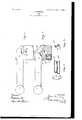
- Figure l is a plan of the lock.
- Fig. 2 is a plan with the top of the casing removed.
- Fig. 3 is a plan of the key to the lock, and
- Fig. 4 is an end view of the key.
- the lock-bolt is indicated at 6. This is preferably circular in shape and may be of any length desired. At one end it has a ball or enlargement 7, which is larger than the staple or ring through which the bolt is to be passed. At the other end the bolt has an offset head 8, which is beveled at the end on its forward side, as indicated at 9, and has a backwardlydirected face, as at 10, which contacts with the tumbler of the lock to prevent release. Opposite said face, at a small distance therefrom, is a projection 11 on the bolt, the object of which is to cover the point of the tumbler and prevent the operation thereof in an unauthorized manner.
- the lock-casing is indicated at 12 and is so large that it will not pass through the staple on which the lock is to be used. It is hollow to receive the head 8 and has a recess which contains the sliding tumbler 13, which works laterally with respect to the bolt, behind the head thereof, between the face 10 and the projection 11. A spring 14 behind the turnbler normally projects it to engagement.
- the head of the tumbler is beveled, as at 15,
- the cover of the casing has a keyhole (indicated at 16) of proper shape and size to receive the key 17, the keyhole being through a rotatable plug or section 6 of the casing.
- the head of the bolt has a curved groove 18, the beginning of which registers with the upper end of the keyhole and which extends thence in a direction toward the point of the tumbler.
- the head also has a groove 19, the beginning of which registers with the lower end of the keyhole and which extends thence on a line parallel to the bolt to the front edge or face of the head.
Landscapes
- Engineering & Computer Science (AREA)
- Mechanical Engineering (AREA)
- Toys (AREA)
Description
10. 779,594 PATENTED JAN. 10, 1905.
Y I. GREENBERG.
LOOK.
APPLICATION FILED JAN 4, 1904.
UNITED STATES Patented January 10, 1905.
PATENT OFFICE.
JESSE GREENBERG, OF CLEVELAND, OHIO, ASSIGNOR OF ONE-HALF TO JOSEPH F. MATLOCK, OF CLEVELAND, OHIO.
LOCK.
SPECIFICATION forming part of Letters Patent No. 779,594, dated January 10, 1905.
Application filed January 4, 1904. Serial No. 187,715-
To all whom it may concern:
Be it known that I, J ESSE GREENBERG, a citizen of the United States, residing at Cleveland, in the county of Ouyahoga and State of Ohio, have invented new and useful Improvements in Locks, of which the following is a specification.
This invention is a lock particularly adapted for use in looking mail-bags, and in such use its bolt is passed through a staple which engages the flaps of the bag. It is not, however, limited to such use, but is readily applicable as a hasp-lock or to any use wherein a bolt may be passed under or through a staple or ring to lock parts associated therewith.
The object of the invention is to form an improved device of the kind, as will more fully hereinafter appear.
In the accompanying drawings, Figure l is a plan of the lock. Fig. 2 is a plan with the top of the casing removed. Fig. 3 is a plan of the key to the lock, and Fig. 4 is an end view of the key.
Referring specifically to the drawings, the lock-bolt is indicated at 6. This is preferably circular in shape and may be of any length desired. At one end it has a ball or enlargement 7, which is larger than the staple or ring through which the bolt is to be passed. At the other end the bolt has an offset head 8, which is beveled at the end on its forward side, as indicated at 9, and has a backwardlydirected face, as at 10, which contacts with the tumbler of the lock to prevent release. Opposite said face, at a small distance therefrom, is a projection 11 on the bolt, the object of which is to cover the point of the tumbler and prevent the operation thereof in an unauthorized manner.
The lock-casing is indicated at 12 and is so large that it will not pass through the staple on which the lock is to be used. It is hollow to receive the head 8 and has a recess which contains the sliding tumbler 13, which works laterally with respect to the bolt, behind the head thereof, between the face 10 and the projection 11. A spring 14 behind the turnbler normally projects it to engagement. The head of the tumbler is beveled, as at 15,
so that it will yield on contact with the face 9 when the bolt is sent home into the casing. By engagement of the tumbler behind the head the release of the bolt from the casing is prevented and the lock maintained. The cover of the casing has a keyhole (indicated at 16) of proper shape and size to receive the key 17, the keyhole being through a rotatable plug or section 6 of the casing. The head of the bolt has a curved groove 18, the beginning of which registers with the upper end of the keyhole and which extends thence in a direction toward the point of the tumbler. The head also has a groove 19, the beginning of which registers with the lower end of the keyhole and which extends thence on a line parallel to the bolt to the front edge or face of the head.
When the key is inserted in the keyhole, its bit 17 pivots in the end of the groove 19 and its bit 17 enters the groove 18, and when the key is turned the bit 17 swings around against the point of the tumbler 13 and forces the same backward into the casing, permitting the withdrawal of the head of the bolt from the casing, at which action the bit 17 slides along the groove 19. WVhen the bolt is in serted in the loclccasing, the beveled head 9 by contact with the bevel 15 and the tumbler depresses the tumbler, the spring yielding to permit the action, and when the bolt is sent home the projection 11 covers the opening in the casing, as heretofore indicated.
What I claim as new, and desire to secure by Letters Patent, is
The combination with a lock-casing having a keyhole, and a spring-tumbler therein, of a bolt, having a projection engaging behind the tumbler, and grooves which register with the keyhole and shaped to receive key-bits and form a pivot-bearing therefor and permit the turn of the key against the tumbler.
In testimony whereofI have signed my name to this specification in the presence of two subscribing witnesses.
JESSE GREENBERG.
Witnesses:
JOHN A. BOMMHARDT, LOT'IIE NEWBURN.
Priority Applications (1)
| Application Number | Priority Date | Filing Date | Title |
|---|---|---|---|
| US1904187715 US779594A (en) | 1904-01-04 | 1904-01-04 | Lock. |
Applications Claiming Priority (1)
| Application Number | Priority Date | Filing Date | Title |
|---|---|---|---|
| US1904187715 US779594A (en) | 1904-01-04 | 1904-01-04 | Lock. |
Publications (1)
| Publication Number | Publication Date |
|---|---|
| US779594A true US779594A (en) | 1905-01-10 |
Family
ID=2848078
Family Applications (1)
| Application Number | Title | Priority Date | Filing Date |
|---|---|---|---|
| US1904187715 Expired - Lifetime US779594A (en) | 1904-01-04 | 1904-01-04 | Lock. |
Country Status (1)
| Country | Link |
|---|---|
| US (1) | US779594A (en) |
-
1904
- 1904-01-04 US US1904187715 patent/US779594A/en not_active Expired - Lifetime
Similar Documents
| Publication | Publication Date | Title |
|---|---|---|
| US786842A (en) | Keyhole-guard. | |
| US2199336A (en) | Lock | |
| US779594A (en) | Lock. | |
| US977085A (en) | Lock. | |
| US1556242A (en) | Pin-tumbler lock | |
| US1546021A (en) | Padlock | |
| US564515A (en) | Hasp-lock | |
| US843200A (en) | Door-lock. | |
| US720455A (en) | Combined lock and latch. | |
| US391826A (en) | taylor | |
| US1031335A (en) | Padlock. | |
| US619524A (en) | Adelbert j | |
| US326673A (en) | Thirds to kaztmlerz pacioekowski | |
| US710722A (en) | Padlock. | |
| US1150450A (en) | Door-bolt. | |
| US255118A (en) | Hasp-lock | |
| US433291A (en) | Key-hole guard | |
| US559467A (en) | Oscar stoddard | |
| US352957A (en) | Key-fastener | |
| US973920A (en) | Lock. | |
| US1360057A (en) | Lock | |
| US1102118A (en) | Jimmy-proof lock. | |
| US1015908A (en) | Lock for mail-bags and the like. | |
| US964331A (en) | Lock. | |
| US1142830A (en) | Lock for switch-arms. |