US7778436B2 - Vibration-sound generating device and yoke thereof - Google Patents
Vibration-sound generating device and yoke thereof Download PDFInfo
- Publication number
- US7778436B2 US7778436B2 US11/345,335 US34533506A US7778436B2 US 7778436 B2 US7778436 B2 US 7778436B2 US 34533506 A US34533506 A US 34533506A US 7778436 B2 US7778436 B2 US 7778436B2
- Authority
- US
- United States
- Prior art keywords
- yoke
- vibration
- generating device
- sound generating
- magnet
- Prior art date
- Legal status (The legal status is an assumption and is not a legal conclusion. Google has not performed a legal analysis and makes no representation as to the accuracy of the status listed.)
- Expired - Fee Related, expires
Links
Images


Classifications
-
- H—ELECTRICITY
- H04—ELECTRIC COMMUNICATION TECHNIQUE
- H04R—LOUDSPEAKERS, MICROPHONES, GRAMOPHONE PICK-UPS OR LIKE ACOUSTIC ELECTROMECHANICAL TRANSDUCERS; DEAF-AID SETS; PUBLIC ADDRESS SYSTEMS
- H04R9/00—Transducers of moving-coil, moving-strip, or moving-wire type
- H04R9/02—Details
- H04R9/025—Magnetic circuit
-
- B—PERFORMING OPERATIONS; TRANSPORTING
- B06—GENERATING OR TRANSMITTING MECHANICAL VIBRATIONS IN GENERAL
- B06B—METHODS OR APPARATUS FOR GENERATING OR TRANSMITTING MECHANICAL VIBRATIONS OF INFRASONIC, SONIC, OR ULTRASONIC FREQUENCY, e.g. FOR PERFORMING MECHANICAL WORK IN GENERAL
- B06B1/00—Methods or apparatus for generating mechanical vibrations of infrasonic, sonic, or ultrasonic frequency
- B06B1/02—Methods or apparatus for generating mechanical vibrations of infrasonic, sonic, or ultrasonic frequency making use of electrical energy
- B06B1/04—Methods or apparatus for generating mechanical vibrations of infrasonic, sonic, or ultrasonic frequency making use of electrical energy operating with electromagnetism
- B06B1/045—Methods or apparatus for generating mechanical vibrations of infrasonic, sonic, or ultrasonic frequency making use of electrical energy operating with electromagnetism using vibrating magnet, armature or coil system
-
- H—ELECTRICITY
- H02—GENERATION; CONVERSION OR DISTRIBUTION OF ELECTRIC POWER
- H02K—DYNAMO-ELECTRIC MACHINES
- H02K33/00—Motors with reciprocating, oscillating or vibrating magnet, armature or coil system
- H02K33/18—Motors with reciprocating, oscillating or vibrating magnet, armature or coil system with coil systems moving upon intermittent or reversed energisation thereof by interaction with a fixed field system, e.g. permanent magnets
-
- H—ELECTRICITY
- H04—ELECTRIC COMMUNICATION TECHNIQUE
- H04R—LOUDSPEAKERS, MICROPHONES, GRAMOPHONE PICK-UPS OR LIKE ACOUSTIC ELECTROMECHANICAL TRANSDUCERS; DEAF-AID SETS; PUBLIC ADDRESS SYSTEMS
- H04R2209/00—Details of transducers of the moving-coil, moving-strip, or moving-wire type covered by H04R9/00 but not provided for in any of its subgroups
- H04R2209/024—Manufacturing aspects of the magnetic circuit of loudspeaker or microphone transducers
-
- H—ELECTRICITY
- H04—ELECTRIC COMMUNICATION TECHNIQUE
- H04R—LOUDSPEAKERS, MICROPHONES, GRAMOPHONE PICK-UPS OR LIKE ACOUSTIC ELECTROMECHANICAL TRANSDUCERS; DEAF-AID SETS; PUBLIC ADDRESS SYSTEMS
- H04R2307/00—Details of diaphragms or cones for electromechanical transducers, their suspension or their manufacture covered by H04R7/00 or H04R31/003, not provided for in any of its subgroups
- H04R2307/025—Diaphragms comprising polymeric materials
-
- H—ELECTRICITY
- H04—ELECTRIC COMMUNICATION TECHNIQUE
- H04R—LOUDSPEAKERS, MICROPHONES, GRAMOPHONE PICK-UPS OR LIKE ACOUSTIC ELECTROMECHANICAL TRANSDUCERS; DEAF-AID SETS; PUBLIC ADDRESS SYSTEMS
- H04R2307/00—Details of diaphragms or cones for electromechanical transducers, their suspension or their manufacture covered by H04R7/00 or H04R31/003, not provided for in any of its subgroups
- H04R2307/027—Diaphragms comprising metallic materials
-
- H—ELECTRICITY
- H04—ELECTRIC COMMUNICATION TECHNIQUE
- H04R—LOUDSPEAKERS, MICROPHONES, GRAMOPHONE PICK-UPS OR LIKE ACOUSTIC ELECTROMECHANICAL TRANSDUCERS; DEAF-AID SETS; PUBLIC ADDRESS SYSTEMS
- H04R2307/00—Details of diaphragms or cones for electromechanical transducers, their suspension or their manufacture covered by H04R7/00 or H04R31/003, not provided for in any of its subgroups
- H04R2307/029—Diaphragms comprising fibres
-
- H—ELECTRICITY
- H04—ELECTRIC COMMUNICATION TECHNIQUE
- H04R—LOUDSPEAKERS, MICROPHONES, GRAMOPHONE PICK-UPS OR LIKE ACOUSTIC ELECTROMECHANICAL TRANSDUCERS; DEAF-AID SETS; PUBLIC ADDRESS SYSTEMS
- H04R2400/00—Loudspeakers
- H04R2400/03—Transducers capable of generating both sound as well as tactile vibration, e.g. as used in cellular phones
Definitions
- This document relates to a vibration-sound generating device and yoke thereof and more particularly, a vibration-sound generating device and yoke thereof having improved vibration and sound performance.
- vibration-sound device which integrates a vibration motor, a receiver and a speaker so as to decrease in size and manufacturing price of the mobile terminal is augmented.
- Such vibration-sound devices according to the conventional art are disclosed in Korean Patent No. 10-0272305.
- the vibration-sound device disclosed in KR Patent No. 10-0272305 functions by virtue of electromagnetic forces generated between a voice coil and a magnetic vibration part, which is composed of a yoke and a magnet when an alternating current is provided to the voice coil.
- the electromagnetic force is changed because the alternating current is provided into the voice coil. Consequently, the magnet and yoke which are supported by a suspension are vibrated by means of the electromagnetic force acted on the magnetic vibration part.
- Such generated vibration is transmitted to a case of the terminal through the suspension and the mobile terminal is vibrated accordingly.
- a diaphragm is attached on the voice coil and vibrated due to the force change of the alternating current provided into the voice coil thus, sound is generated.
- the magnitude of vibration of a vibration-sound device is in proportion to the mass sum of a magnet, a yoke and a suspension that support the magnet. But the mass of the suspension and yoke of the conventional vibration-sound device is not high enough to generate desired sufficient vibration.
- a poise that has more specific gravity than iron, is attached to the periphery of the yoke. But the conventional art which fabricates an extra poise and attaches it to the periphery of the yoke not only requires an additional process of attachment of the poise but also brings about a possibility of contact between the magnetic vibration part and the voice coil when the center of the poise and the yoke are eccentric.
- the magnitude of sound generated by a vibration-sound device is in proportion to the intensity of a magnetic field of internal yoke in which a voice coil is positioned.
- conventional vibration-sound devices have poor performance of a speaker because the magnetic flux passes through the voice coil is insufficient. This is because the volume of a magnet is limited due to the addition of the magnetic vibration part that generates vibration in compared to the usual speaker having a magnetic circuit part. Consequently, there is a necessity of magnetic field having sufficient magnetic flux density pass through the voice coil in order to improve the performance of the speaker.
- the present invention provides vibration-sound generating devices having improved performance of vibration and speaker.
- the invention features a vibration-sound generating device comprising a diaphragm, a vibration part comprising a magnet and a yoke which is positioned apart from the diaphragm by a desired distance, a suspension elastically supporting the vibration part, a supporting part supporting the diaphragm and the suspension, and a voice coil electromagnetically driving the diaphragm and the vibration part wherein the yoke has higher specific gravity and magnetic permeability than iron.
- the invention features a vibration-sound generating device comprising a diaphragm, a vibration part comprising a magnet and a yoke which is positioned apart from the diaphragm by a desired distance, a suspension elastically supporting the vibration part, a supporting part supporting the diaphragm and the suspension, a voice coil electromagnetically driving the diaphragm, and a vibration coil electromagnetically driving the vibration part, wherein the yoke has more specific gravity and magnetic permeability than iron.
- the yoke is formed from iron, one selected from a group consisting of osmium, platinum, tungsten and gold, and the other selected from a group consisting of nickel and cobalt.
- the yoke is formed from iron, tungsten and nickel. More preferably the yoke comprises 4.4 wt %-50 wt % tungsten.
- the yoke can be formed from injection molding of a mixture of iron, tungsten and nickel powder and sintering of it.
- the yoke can be also formed from tungsten and one selected from a group consisting of Permalloy, Mo Permalloy, Mumetal and Supermalloy.
- the yoke can comprise upper yoke and lower yoke attached respectively to the upper and lower surface of the magnet. And the yoke and the supporting part are preferably oval-shaped.
- FIG. 1 is a plane view illustrating inner structure of a vibration-sound generating device according to one embodiment of the present invention.
- FIG. 2 is a sectional view illustrating a vibration-sound generating device on the line of AA′ as illustrated in FIG. 1 .
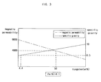
- FIG. 3 is a graph illustrating the change of specific gravity and magnetic permeability according to the change of the weight rate of Tungsten.
- FIG. 4 is a sectional view illustrating a state of magnetic flux passing through a voice coil according to the conventional vibration-sound generating device.
- FIG. 5 is a sectional view illustrating a state of increased density of magnetic flux passing through a voice coil according to one embodiment of the present invention.
- FIG. 6 is a sectional view of a vibration-sound generating device according to another embodiment of the present invention.
- FIG. 7 is a sectional view illustrating generation of the sound and vibration according to another embodiment of the present invention.
- FIG. 1 is a plane view illustrating inner structure of a vibration-sound generating device according to one embodiment of the present invention and FIG. 2 is a sectional view on the line of AA′ as illustrated in FIG. 1 .
- the vibration-sound generating device of one embodiment of the present invention comprises a diaphragm 10 , a vibration part 30 , a suspension 50 , a supporting part 71 , and a voice coil 91 .
- the diaphragm 10 is attached on upper surface of the supporting part 71 .
- the diaphragm 10 is formed of titan or polycarbonate and has a thickness of 10 ⁇ m-50 ⁇ m.
- the diaphragm 10 attached to the voice coil 91 is vibrates and generates sound; this is because the electromagnetic force produced in accordance with the change of electric signal that is provided into the voice coil 91 .
- the suspension 50 fixes the vibration part 30 upon the supporting part 71 and transmits the oscillation of the vibration part 30 to the supporting part 71 .
- the suspension 50 is attached upon the lower surfaces of the vibration part 30 and the supporting part 71 , respectively and has four arms 51 which connect the vibration part 30 to the supporting part 71 .
- the number of the arm 51 is preferably more than three to prevent from rolling of the vibration part 30 .
- the suspension 50 can be anything that connects the vibration part 30 to the supporting part 71 and transmits vibration generated by the vibration part 30 to the supporting part 71 .
- the suspension 50 can be a spring that connects the vibration part 30 to the supporting part 71 .
- the supporting part 71 has a short cylinder shape and supports the diaphragm 10 and the vibration part 30 .
- the supporting part 71 can be formed from crashworthy plastic, such as fiberglass-reinforced plastic (FRP).
- FRP fiberglass-reinforced plastic
- the supporting part 71 is positioned generally in a receipt of the terminal. It is preferred that the supporting part 71 has an oval shape to reduce volume of the vibration-sound generating device.
- the voice coil 91 can be fabricated by winding a coil coated with insulating layer and adhesive layer around a conduct such as copper or aluminum.
- the voice coil 91 is positioned between the magnet 31 and the lower yoke 35 .
- the voice coil 91 generates sound by transmitting the vibration to the diaphragm 10 , wherein the vibration is produced by cooperation between a magnet field generated by the magnet 31 and an electric field generated by currents applied to the voice coil 91 .
- the vibration of the diaphragm 10 by providing currents into the voice coil 91 is generated on account of the Fleming's left-hand rule. Because the alternating current having variable baseband is input into the voice coil 91 , the vibration part 30 vibrates and generates mechanical vibrations and the diaphragm 10 vibrates and generates sound in accordance with the change in frequency.
- the vibration part 30 comprises the magnet 31 , an upper yoke 33 and a lower yoke 35 and is vibrated by the voice coil 91 when it is elastically supported by the suspension 50 .
- the lower yoke 35 can be formed to oval type to reduce the volume of the vibration-sound generating device.
- the magnet 31 is a permanent magnet formed from ferrite or neodymium and has a disc shape.
- the magnet 31 is attached upon the lower surface of the upper yoke 33 and the upper surface of the lower yoke 35 .
- the N pole of the magnet 31 is contacted to the upper yoke 33 and the S pole is contacted to the lower yoke 35 . Accordingly, as illustrated in FIG. 6 , the magnet flux comes from the N pole enters the S pole passing through the lower yoke 35 and the voice coil 91 .
- the upper yoke 33 as illustrated in FIG. 1 and FIG. 2 , has a disc shape which is corresponding to the sectional shape of the magnet 31 and is attached upon the magnet 31 .
- the lower yoke 35 has a cylinder shape of which the upper part is opened. And the lower part of the lower yoke 35 is supported by the suspension 50 and connected to the supporting part 71 .
- the upper yoke 33 and lower yoke 35 are formed out of iron and materials which have higher specific gravity and magnetic permeability than iron to improve performance of vibration and speaker.
- the materials which have higher specific gravity and magnetic permeability than iron are osmium (specific gravity 22.5), platinum (specific gravity 21.45), tungsten (specific gravity 19.3), gold (specific gravity 19.29) and so forth.
- examples of ferromagnetic materials include iron, nickel, cobalt and so forth. Consequently, in order to improve specific gravity and magnetic permeability of the yoke, it formed out of iron, one selected from a group consisting of osmium, platinum and gold, and the other selected from a group consisting of nickel and cobalt.
- FIG. 3 illustrates specific gravity and magnetic permeability of the yoke according to the rate change of tungsten.
- the x axis represents weight percent (wt %) of tungsten (at this point, iron and nickel are in the ratio of four to one) and the y axis represents magnetic permeability (B/H) and specific gravity.
- Tungsten (W) has specific gravity of 19.3 at 0°, which is twice more than iron (7.8), and is inexpensive.
- FIG. 3 it is seen that as the weigh percent of tungsten is increased as compared to that of the iron and nickel, the specific gravity of the yoke is increased. But, if the weight percent of tungsten is decreased and the weight percent of iron and nickel is increased, the specific gravity of the yoke is reduced. Accordingly, to acquire desired specific gravity and magnetic permeability, it is necessary to control the weight percent of tungsten and nickel adequately. In this embodiment, to acquire more than 8.5 of the specific gravity and 4000 B/H of the magnetic permeability, as illustrated in FIG.
- the weigh percent of tungsten can be in the range of from 4.4 wt % to 50 wt %. Namely, if the yoke comprises tungsten 4.4 wt %, iron 76.5 wt % and nickel 19.1 wt %, it has 8.5 of the specific gravity. Therefore, to acquire more than 8.5 of the specific gravity of the yoke, it is necessary to increase the weight percent of tungsten to more than 4.4 wt %.
- the yoke is formed from tungsten 50 wt %, iron 40 wt % and nickel 10 wt %, it has 4000B/H permeability, and therefore it is necessary to control the weigh percent of the tungsten less than 50 wt %.
- the present invention is not limited the above weight percent and the weight percent of the tungsten and nickel are adjustable according to where to place a great deal of weight in performance of vibration or speaker.
- the weight percent of tungsten can be increased to improve the performance of vibration.
- the weight percent of the nickel can be increased to improve the performance of speaker.
- the upper yoke 33 and lower yoke 35 can be formed from an alloy of tungsten and nickel alloy, such as permalloy, Mo permalloy or supermalloy.
- the permalloy composed of iron and 75 wt %-79 wt % of nickel has a maximum permeability of 105,000 (B/H), which is much bigger than common iron alloy.
- the improvement of the permalloy is Mo permalloy which replace a portion of the iron of the permalloy with molybdenum or chrome and has about 20,000 (B/H) of an initial permeability and 90,000 (B/H) of a maximum permeability.
- Supermalloy a kind of Mo permalloy, is composed of 79 wt % nickel, 1.5 wt % chrome, and 5 wt % copper and has an initial permeability of 120,000 (B/H) and a maximum permeability of 900,000 (B/H).
- the upper yoke 33 and lower yoke 35 can be formed from an injection molding of a mixture of iron, tungsten and nickel powder and a sintering process at a temperature of about 1250° C.
- FIG. 4 is a sectional view of the magnetic flux passing through the voice coil according to the conventional vibration-sound generating device and FIG. 5 is a sectional view illustrating a state of increased density of magnetic flux passing through the voice coil according to one embodiment of the present invention.
- B density of the magnet flux
- I density of the current passing through the voice coil 91
- L is length of the voice coil
- F force exerted to the voice coil 91 .
- the density of the magnet flux B is increased because the yoke formed from nickel or nickel alloy facilitates the magnetic flux to concentrate on the voice coil 91 . Accordingly, force exerted to the voice coil 91 is increased and the intensity of the vibration of the voice coil 91 is augmented. As a result, the performance of speaker is improved.
- the alternating current with a frequency corresponding to the resonance frequency of the vibration part 30 is input into the voice coil 91 to drive the vibration part 30 .
- the resonance frequency of the vibration part 30 is in the range of 100 Hz-250 Hz and of course, the range can be altered according to the designed condition.
- the alternating current is input into the voice coil 91 , force is exerted on the voice coil 91 ; this force vibrates the diaphragm 10 which is attached to the voice coil 91 at a range of audio frequency. If the frequency of the alternating current which is input into the voice coil 91 is higher than the resonance frequency of 250 Hz of the vibration part 30 , the vibration part 30 is scarcely vibrated because it is out of the resonance frequency. But the diaphragm 10 is vibrated with the audio frequency so that it produces sound.
- the upper yoke 33 and the lower yoke 35 involve nickel which has higher magnetic permeability than iron, the magnetic flux passing through the voice coil 91 are increased. Therefore, more force is exerted to the voice coil 91 and the performance of speaker is improved.
- the vibration-sound generating device of another embodiment of the present invention comprises the diaphragm 10 , a vibration part 30 ′, the suspension 50 , the supporting part 71 , the voice coil 91 , and a vibration coil 93 .
- the diaphragm 10 , suspension 50 , supporting part 71 and voice coil 90 have same structure and function to the above embodiment; the following will explain the vibration part 30 ′ and vibration part 93 .
- the vibration part 30 ′ comprises a magnet 31 ′, a upper yoke 33 ′ and a lower yoke 35 ′.
- the magnet 31 ′ has a donut shape, and the upper and lower surface on which the upper yoke 33 ′ and lower yoke upper 35 ′ are attached respectively.
- the upper yoke 33 ′ is supported elastically to the supporting part 71 by the suspension 50 .
- the lower yoke 35 ′ attached to the magnet 31 ′ is mounted on the lower surface of the suspension 50 .
- the voice coil 91 is attached to the lower surface of the diaphragm 10 and protruded between the magnet 31 ′ and the lower yoke 35 ′.
- the vibration coil 93 is attached to the lower cover 75 and protruded between the magnet 31 ′ and the upper yoke 33 ′.
- the upper yoke 33 ′ and the lower yoke 35 ′ are formed from a material having high specific gravity and magnetic permeability as in the first embodiment.
- “ 73 ” is the upper cover which protects the diaphragm 10 .
- the magnetic flux forms a magnetic field that comes from the N pole of the magnet 31 ′, passes through the upper yoke 33 ′ and lower yoke 35 ′ and then directs to the S pole of the magnet 30 ′. If a high frequency current is provided into the voice coil 91 , the voice coil 91 is vibrated upwardly and downwardly by the cooperation between the magnetic field generated by the magnet 31 ′ and the electric field generated by the voice coil 91 . As a result, the diaphragm 10 is vibrated upwardly and downwardly and generates a sound.
- the vibration part 30 ′ is vibrated upwardly and downwardly by the cooperation between the magnetic field generated by the magnet 31 ′ and the electric field generated by the voice coil 91 . As a result, the vibration-sound generating device is vibrated.
- the present invention can provide vibration-sound generating devices and yoke thereof having improved performance of vibration and sound because the yoke has high specific gravity and magnetic permeability.
- the vibration-sound generating devices and yoke thereof according to the present invention can reduce its volume because of the improvement of the performance of vibration and sound. Therefore, the present invention facilities the design of the mobile terminal such as cellular phone and PDA.
Abstract
A vibration-sound generating device and yoke thereof are described. The vibration-sound generating device comprises a diaphragm, a vibration part comprising a magnet and a yoke, which is positioned apart from the diaphragm by a desired distance, a suspension elastically supporting the vibration part, a supporting part supporting the diaphragm and the suspension, and a voice coil electromagnetically driving the diaphragm and the vibration part. The yoke of the invention has higher specific gravity and magnetic permeability than iron. So that it can improve performance of vibration and sound device.
Description
This application claims the benefit of Korean Patent Application No. 2005-31490 filed with the Korea Industrial Property Office on Apr. 15, 2005, the disclosure of which is incorporated herein by reference.
1. Field of the Invention
This document relates to a vibration-sound generating device and yoke thereof and more particularly, a vibration-sound generating device and yoke thereof having improved vibration and sound performance.
2. Description of the Related Art
Recently, the release of mobile terminal, such as cellular phone or PDA, having camera and sound performance is increased rapidly. Accordingly, the needs for smaller mobile terminal is increasing, the use of vibration-sound device, which integrates a vibration motor, a receiver and a speaker so as to decrease in size and manufacturing price of the mobile terminal is augmented. Such vibration-sound devices according to the conventional art are disclosed in Korean Patent No. 10-0272305.
The vibration-sound device disclosed in KR Patent No. 10-0272305 functions by virtue of electromagnetic forces generated between a voice coil and a magnetic vibration part, which is composed of a yoke and a magnet when an alternating current is provided to the voice coil. The electromagnetic force is changed because the alternating current is provided into the voice coil. Consequently, the magnet and yoke which are supported by a suspension are vibrated by means of the electromagnetic force acted on the magnetic vibration part. Such generated vibration is transmitted to a case of the terminal through the suspension and the mobile terminal is vibrated accordingly. Besides, a diaphragm is attached on the voice coil and vibrated due to the force change of the alternating current provided into the voice coil thus, sound is generated.
The magnitude of vibration of a vibration-sound device is in proportion to the mass sum of a magnet, a yoke and a suspension that support the magnet. But the mass of the suspension and yoke of the conventional vibration-sound device is not high enough to generate desired sufficient vibration. To solve such a problem, a poise, that has more specific gravity than iron, is attached to the periphery of the yoke. But the conventional art which fabricates an extra poise and attaches it to the periphery of the yoke not only requires an additional process of attachment of the poise but also brings about a possibility of contact between the magnetic vibration part and the voice coil when the center of the poise and the yoke are eccentric.
The magnitude of sound generated by a vibration-sound device is in proportion to the intensity of a magnetic field of internal yoke in which a voice coil is positioned. But conventional vibration-sound devices have poor performance of a speaker because the magnetic flux passes through the voice coil is insufficient. This is because the volume of a magnet is limited due to the addition of the magnetic vibration part that generates vibration in compared to the usual speaker having a magnetic circuit part. Consequently, there is a necessity of magnetic field having sufficient magnetic flux density pass through the voice coil in order to improve the performance of the speaker.
The present invention provides vibration-sound generating devices having improved performance of vibration and speaker.
In one aspect, the invention features a vibration-sound generating device comprising a diaphragm, a vibration part comprising a magnet and a yoke which is positioned apart from the diaphragm by a desired distance, a suspension elastically supporting the vibration part, a supporting part supporting the diaphragm and the suspension, and a voice coil electromagnetically driving the diaphragm and the vibration part wherein the yoke has higher specific gravity and magnetic permeability than iron.
Additional aspects and advantages of the present general inventive concept will be set forth in part in the description which follows and, in part, will be obvious from the description, or may be learned by practice of the general inventive concept.
In another aspect, the invention features a vibration-sound generating device comprising a diaphragm, a vibration part comprising a magnet and a yoke which is positioned apart from the diaphragm by a desired distance, a suspension elastically supporting the vibration part, a supporting part supporting the diaphragm and the suspension, a voice coil electromagnetically driving the diaphragm, and a vibration coil electromagnetically driving the vibration part, wherein the yoke has more specific gravity and magnetic permeability than iron.
The yoke is formed from iron, one selected from a group consisting of osmium, platinum, tungsten and gold, and the other selected from a group consisting of nickel and cobalt. Preferably, the yoke is formed from iron, tungsten and nickel. More preferably the yoke comprises 4.4 wt %-50 wt % tungsten.
The yoke can be formed from injection molding of a mixture of iron, tungsten and nickel powder and sintering of it. The yoke can be also formed from tungsten and one selected from a group consisting of Permalloy, Mo Permalloy, Mumetal and Supermalloy. The yoke can comprise upper yoke and lower yoke attached respectively to the upper and lower surface of the magnet. And the yoke and the supporting part are preferably oval-shaped.
These and/or other aspects and advantages of the present general inventive concept will become apparent and more readily appreciated from the following description of the embodiments, taken in conjunction with the accompanying drawings of which:
Reference will now be made in detail to the embodiments of the present general inventive concept, examples of which are illustrated in the accompanying drawings, wherein like reference numerals refer to the like elements throughout. The embodiments are described below in order to explain the present general inventive concept by referring to the figures.
Referring to FIG. 2 , the diaphragm 10 is attached on upper surface of the supporting part 71. The diaphragm 10 is formed of titan or polycarbonate and has a thickness of 10 μm-50 μm. The diaphragm 10 attached to the voice coil 91 is vibrates and generates sound; this is because the electromagnetic force produced in accordance with the change of electric signal that is provided into the voice coil 91.
The suspension 50 fixes the vibration part 30 upon the supporting part 71 and transmits the oscillation of the vibration part 30 to the supporting part 71. Referring to FIG. 1 and FIG. 2 , the suspension 50 is attached upon the lower surfaces of the vibration part 30 and the supporting part 71, respectively and has four arms 51 which connect the vibration part 30 to the supporting part 71. The number of the arm 51 is preferably more than three to prevent from rolling of the vibration part 30. The suspension 50 can be anything that connects the vibration part 30 to the supporting part 71 and transmits vibration generated by the vibration part 30 to the supporting part 71. For example, the suspension 50 can be a spring that connects the vibration part 30 to the supporting part 71.
The supporting part 71 has a short cylinder shape and supports the diaphragm 10 and the vibration part 30. The supporting part 71 can be formed from crashworthy plastic, such as fiberglass-reinforced plastic (FRP). The supporting part 71 is positioned generally in a receipt of the terminal. It is preferred that the supporting part 71 has an oval shape to reduce volume of the vibration-sound generating device.
The voice coil 91 can be fabricated by winding a coil coated with insulating layer and adhesive layer around a conduct such as copper or aluminum. The voice coil 91 is positioned between the magnet 31 and the lower yoke 35. The voice coil 91 generates sound by transmitting the vibration to the diaphragm 10, wherein the vibration is produced by cooperation between a magnet field generated by the magnet 31 and an electric field generated by currents applied to the voice coil 91. The vibration of the diaphragm 10 by providing currents into the voice coil 91 is generated on account of the Fleming's left-hand rule. Because the alternating current having variable baseband is input into the voice coil 91, the vibration part 30 vibrates and generates mechanical vibrations and the diaphragm 10 vibrates and generates sound in accordance with the change in frequency.
The vibration part 30 comprises the magnet 31, an upper yoke 33 and a lower yoke 35 and is vibrated by the voice coil 91 when it is elastically supported by the suspension 50. The lower yoke 35 can be formed to oval type to reduce the volume of the vibration-sound generating device.
It is preferred that the magnet 31 is a permanent magnet formed from ferrite or neodymium and has a disc shape. The magnet 31 is attached upon the lower surface of the upper yoke 33 and the upper surface of the lower yoke 35. The N pole of the magnet 31 is contacted to the upper yoke 33 and the S pole is contacted to the lower yoke 35. Accordingly, as illustrated in FIG. 6 , the magnet flux comes from the N pole enters the S pole passing through the lower yoke 35 and the voice coil 91.
The upper yoke 33, as illustrated in FIG. 1 and FIG. 2 , has a disc shape which is corresponding to the sectional shape of the magnet 31 and is attached upon the magnet 31. The lower yoke 35 has a cylinder shape of which the upper part is opened. And the lower part of the lower yoke 35 is supported by the suspension 50 and connected to the supporting part 71.
The upper yoke 33 and lower yoke 35 are formed out of iron and materials which have higher specific gravity and magnetic permeability than iron to improve performance of vibration and speaker. The materials which have higher specific gravity and magnetic permeability than iron (specific gravity 7.8) are osmium (specific gravity 22.5), platinum (specific gravity 21.45), tungsten (specific gravity 19.3), gold (specific gravity 19.29) and so forth. And examples of ferromagnetic materials include iron, nickel, cobalt and so forth. Consequently, in order to improve specific gravity and magnetic permeability of the yoke, it formed out of iron, one selected from a group consisting of osmium, platinum and gold, and the other selected from a group consisting of nickel and cobalt.
Tungsten (W) has specific gravity of 19.3 at 0°, which is twice more than iron (7.8), and is inexpensive. Referring to FIG. 3 , it is seen that as the weigh percent of tungsten is increased as compared to that of the iron and nickel, the specific gravity of the yoke is increased. But, if the weight percent of tungsten is decreased and the weight percent of iron and nickel is increased, the specific gravity of the yoke is reduced. Accordingly, to acquire desired specific gravity and magnetic permeability, it is necessary to control the weight percent of tungsten and nickel adequately. In this embodiment, to acquire more than 8.5 of the specific gravity and 4000 B/H of the magnetic permeability, as illustrated in FIG. 3 , the weigh percent of tungsten can be in the range of from 4.4 wt % to 50 wt %. Namely, if the yoke comprises tungsten 4.4 wt %, iron 76.5 wt % and nickel 19.1 wt %, it has 8.5 of the specific gravity. Therefore, to acquire more than 8.5 of the specific gravity of the yoke, it is necessary to increase the weight percent of tungsten to more than 4.4 wt %. In addition, if the yoke is formed from tungsten 50 wt %, iron 40 wt % and nickel 10 wt %, it has 4000B/H permeability, and therefore it is necessary to control the weigh percent of the tungsten less than 50 wt %.
The present invention is not limited the above weight percent and the weight percent of the tungsten and nickel are adjustable according to where to place a great deal of weight in performance of vibration or speaker. In other words, the weight percent of tungsten can be increased to improve the performance of vibration. And the weight percent of the nickel can be increased to improve the performance of speaker.
The upper yoke 33 and lower yoke 35 can be formed from an alloy of tungsten and nickel alloy, such as permalloy, Mo permalloy or supermalloy. The permalloy composed of iron and 75 wt %-79 wt % of nickel has a maximum permeability of 105,000 (B/H), which is much bigger than common iron alloy. The improvement of the permalloy is Mo permalloy which replace a portion of the iron of the permalloy with molybdenum or chrome and has about 20,000 (B/H) of an initial permeability and 90,000 (B/H) of a maximum permeability. Supermalloy, a kind of Mo permalloy, is composed of 79 wt % nickel, 1.5 wt % chrome, and 5 wt % copper and has an initial permeability of 120,000 (B/H) and a maximum permeability of 900,000 (B/H).
The upper yoke 33 and lower yoke 35 can be formed from an injection molding of a mixture of iron, tungsten and nickel powder and a sintering process at a temperature of about 1250° C.
In case of the upper yoke 33 and the lower yoke 35 are formed from material having a high permeability, such as nickel and Permalloy, the magnetic flux that comes from the N pole of the magnet 31 are concentrated on the side part of the lower yoke 5. Consequently, the density of the magnetic flux that passes through the voice coil 91 is increased as compared to the conventional vibration-sound generating device as illustrated in FIG. 4 , so that the force to the voice coil 91 is increased by the Fleming's left-hand rule as below,
F=BIL
F=BIL
Wherein B is density of the magnet flux, I is density of the current passing through the voice coil 91, L is length of the voice coil and F is force exerted to the voice coil 91. The density of the magnet flux B is increased because the yoke formed from nickel or nickel alloy facilitates the magnetic flux to concentrate on the voice coil 91. Accordingly, force exerted to the voice coil 91 is increased and the intensity of the vibration of the voice coil 91 is augmented. As a result, the performance of speaker is improved.
If an alternating current is provided into the voice coil 91, driving power is generated between the voice coil 91 and the vibration part 30. Because such driving power is changed according to the intensity of the alternating current input into the voice coil 91, the vibration part 30 is oscillated. And as a result of the oscillation of the vibration part 30, the suspension 50 and the supporting part 71 which are connected to the vibration part 30 are vibrated. At this time, the upper yoke 33 and the lower yoke 35 can have increased intensity of vibration because it has higher specific gravity than the conventional yoke.
Generally, the alternating current with a frequency corresponding to the resonance frequency of the vibration part 30 is input into the voice coil 91 to drive the vibration part 30. The resonance frequency of the vibration part 30 is in the range of 100 Hz-250 Hz and of course, the range can be altered according to the designed condition.
If the alternating current is input into the voice coil 91, force is exerted on the voice coil 91; this force vibrates the diaphragm 10 which is attached to the voice coil 91 at a range of audio frequency. If the frequency of the alternating current which is input into the voice coil 91 is higher than the resonance frequency of 250 Hz of the vibration part 30, the vibration part 30 is scarcely vibrated because it is out of the resonance frequency. But the diaphragm 10 is vibrated with the audio frequency so that it produces sound.
Because the upper yoke 33 and the lower yoke 35 involve nickel which has higher magnetic permeability than iron, the magnetic flux passing through the voice coil 91 are increased. Therefore, more force is exerted to the voice coil 91 and the performance of speaker is improved.
Referring to the FIG. 6 , the vibration-sound generating device of another embodiment of the present invention comprises the diaphragm 10, a vibration part 30′, the suspension 50, the supporting part 71, the voice coil 91, and a vibration coil 93. The diaphragm 10, suspension 50, supporting part 71 and voice coil 90 have same structure and function to the above embodiment; the following will explain the vibration part 30′ and vibration part 93.
As illustrated in FIG. 6 , the vibration part 30′ comprises a magnet 31′, a upper yoke 33′ and a lower yoke 35′. The magnet 31′ has a donut shape, and the upper and lower surface on which the upper yoke 33′ and lower yoke upper 35′ are attached respectively.
The upper yoke 33′ is supported elastically to the supporting part 71 by the suspension 50. The lower yoke 35′ attached to the magnet 31′ is mounted on the lower surface of the suspension 50. The voice coil 91 is attached to the lower surface of the diaphragm 10 and protruded between the magnet 31′ and the lower yoke 35′. The vibration coil 93 is attached to the lower cover 75 and protruded between the magnet 31′ and the upper yoke 33′. The upper yoke 33′ and the lower yoke 35′ are formed from a material having high specific gravity and magnetic permeability as in the first embodiment. In FIG. 6 , “73” is the upper cover which protects the diaphragm 10.
Referring to FIG. 7 , the magnetic flux forms a magnetic field that comes from the N pole of the magnet 31′, passes through the upper yoke 33′ and lower yoke 35′ and then directs to the S pole of the magnet 30′. If a high frequency current is provided into the voice coil 91, the voice coil 91 is vibrated upwardly and downwardly by the cooperation between the magnetic field generated by the magnet 31′ and the electric field generated by the voice coil 91. As a result, the diaphragm 10 is vibrated upwardly and downwardly and generates a sound.
If a low frequency current is provided into the vibration coil 93, the vibration part 30′ is vibrated upwardly and downwardly by the cooperation between the magnetic field generated by the magnet 31′ and the electric field generated by the voice coil 91. As a result, the vibration-sound generating device is vibrated.
Although the foregoing description details various embodiments of the invention, it will be appreciated that the embodiments are only examples of implementing the spirit of the invention, and that any changed or modified examples remain within the scope of the invention so long as they do not depart from the spirit of the invention.
The present invention can provide vibration-sound generating devices and yoke thereof having improved performance of vibration and sound because the yoke has high specific gravity and magnetic permeability.
In addition, the vibration-sound generating devices and yoke thereof according to the present invention can reduce its volume because of the improvement of the performance of vibration and sound. Therefore, the present invention facilities the design of the mobile terminal such as cellular phone and PDA.
Although a few embodiments of the present general inventive concept have been shown and described, it will be appreciated by those skilled in the art that changes may be made in these embodiments without departing from the principles and spirit of the general inventive concept, the scope of which is defined in the appended claims and their equivalents.
Claims (11)
1. A vibration-sound generating device comprising:
a diaphragm;
a vibration part comprising a magnet and a yoke which is positioned apart from the diaphragm by a desired distance;
a suspension elastically supporting the vibration part;
a supporting part supporting the diaphragm and the suspension; and
a voice coil electromagnetically driving the diaphragm and the vibration part,
wherein the yoke is formed from iron, one material selected from a group consisting of osmium, platinum, tungsten and gold, and another material selected from a group consisting of nickel and cobalt.
2. The vibration-sound generating device according to claim 1 , wherein the yoke is formed from iron, tungsten and nickel.
3. The vibration-sound generating device according to claim 2 , wherein the yoke comprises 4.4 wt %-50 wt % tungsten.
4. The vibration-sound generating device according to claim 3 ,
wherein the yoke comprises a upper yoke and a lower yoke attached respectively to the upper and lower surface of the magnet.
5. The vibration-sound generating device according to claim 2 ,
wherein the yoke is formed by an injection molding of a mixture of iron, tungsten, and nickel powder and sintering thereof.
6. The vibration-sound generating device according to claim 5 ,
wherein the yoke comprises a upper yoke and a lower yoke attached respectively to the upper and lower surface of the magnet.
7. The vibration-sound generating device according to claim 2 ,
wherein the yoke is formed from tungsten and one selected from a group consisting of Permalloy, Mo Permalloy, Mumetal, and Supermalloy.
8. The vibration-sound generating device according claim 7 ,
wherein the yoke comprises a upper yoke and a lower yoke attached respectively to the upper and lower surface of the magnet.
9. The vibration-sound generating device according to claim 2 ,
wherein the yoke comprises a upper yoke and a lower yoke attached respectively to the upper and lower surface of the magnet.
10. The vibration-sound generating device according to claim 1 ,
wherein the yoke comprises a upper yoke and a lower yoke attached respectively to the upper and lower surface of the magnet.
11. The vibration-sound generating device according to claim 10 ,
wherein the yoke and the supporting part have oval shape.
Applications Claiming Priority (3)
| Application Number | Priority Date | Filing Date | Title |
|---|---|---|---|
| KR1020050031490A KR100661921B1 (en) | 2005-04-15 | 2005-04-15 | Vibration-Sound Generating Device and Yoke thereof |
| KR2005-31490 | 2005-04-15 | ||
| KR10-2005-0031490 | 2005-04-15 |
Publications (2)
| Publication Number | Publication Date |
|---|---|
| US20060233415A1 US20060233415A1 (en) | 2006-10-19 |
| US7778436B2 true US7778436B2 (en) | 2010-08-17 |
Family
ID=37068078
Family Applications (1)
| Application Number | Title | Priority Date | Filing Date |
|---|---|---|---|
| US11/345,335 Expired - Fee Related US7778436B2 (en) | 2005-04-15 | 2006-02-02 | Vibration-sound generating device and yoke thereof |
Country Status (6)
| Country | Link |
|---|---|
| US (1) | US7778436B2 (en) |
| JP (1) | JP2006304262A (en) |
| KR (1) | KR100661921B1 (en) |
| CN (1) | CN1849014A (en) |
| DE (1) | DE102006002044B4 (en) |
| TW (1) | TWI301383B (en) |
Cited By (2)
| Publication number | Priority date | Publication date | Assignee | Title |
|---|---|---|---|---|
| US8335337B2 (en) | 2007-08-30 | 2012-12-18 | Jl Audio, Inc. | Loudspeaker with replaceable motor assembly |
| USD882552S1 (en) * | 2017-11-06 | 2020-04-28 | Tymphany Acoustic Technology (Huizhou) Co., Ltd. | Yoke for loudspeaker |
Families Citing this family (19)
| Publication number | Priority date | Publication date | Assignee | Title |
|---|---|---|---|---|
| KR100902120B1 (en) * | 2008-10-15 | 2009-06-09 | 주식회사 비에스이 | Multi function speaker |
| KR100895993B1 (en) | 2009-01-07 | 2009-05-07 | 주식회사 블루콤 | Linear vibration device |
| KR101004907B1 (en) * | 2010-06-16 | 2010-12-28 | 삼성전기주식회사 | A linear vibrator and electronic device including the same |
| KR101046003B1 (en) * | 2010-11-17 | 2011-07-04 | 삼성전기주식회사 | Linear vibrator |
| KR101357211B1 (en) * | 2012-11-23 | 2014-02-03 | 이석재 | Driver for horn speaker |
| JP6515392B2 (en) * | 2013-10-29 | 2019-05-22 | ゴールデンダンス株式会社 | Voice vibration generator |
| DE102015102429B3 (en) * | 2015-02-20 | 2016-08-04 | Lisa Dräxlmaier GmbH | Warning device for a motor vehicle door |
| KR20160131822A (en) * | 2015-05-08 | 2016-11-16 | 주식회사 예일전자 | Apparatus for setting up vibration and portable electronic device including apparatus for setting up vibration |
| US9998829B2 (en) * | 2016-06-27 | 2018-06-12 | Google Llc | Bone conduction transducer with increased low frequency performance |
| TW201820891A (en) * | 2016-10-26 | 2018-06-01 | 日商特摩柯日本股份有限公司 | Bone conduction speaker unit |
| DE102018132249A1 (en) * | 2017-12-25 | 2019-06-27 | Futaba Corporation | Vibrational energy generator |
| CN108366327A (en) * | 2018-02-02 | 2018-08-03 | 瑞声科技(新加坡)有限公司 | Loud speaker |
| US20210368271A1 (en) * | 2018-02-26 | 2021-11-25 | Hewlett-Packard Development Company, L.P. | Acoustic transducers with pole plates |
| KR102100823B1 (en) * | 2018-04-11 | 2020-04-21 | 주식회사 엠플러스 | Linear vibration motor |
| KR102016672B1 (en) * | 2018-09-03 | 2019-08-30 | 주식회사 엠플러스 | Sound vibration actuator |
| KR102030604B1 (en) * | 2018-09-19 | 2019-10-10 | 주식회사 엠플러스 | Sound vibration actuator |
| KR20200069132A (en) | 2018-12-06 | 2020-06-16 | 현대자동차주식회사 | Yoke for speaker, Method form manufacturing the same And Speaker device including the same |
| KR102033876B1 (en) * | 2019-05-24 | 2019-10-17 | 주식회사 비츠나인 | Vibration pad and Vibration system using sound comprising the same |
| WO2023158131A1 (en) * | 2022-02-18 | 2023-08-24 | 삼성전자 주식회사 | Electronic device comprising speaker |
Citations (15)
| Publication number | Priority date | Publication date | Assignee | Title |
|---|---|---|---|---|
| CH198198A (en) | 1936-04-09 | 1938-06-15 | Siemens Ag | Permanent magnet alloy. |
| JPS52105813A (en) | 1976-03-02 | 1977-09-05 | Mitsubishi Electric Corp | Magnetic circuit for speaker |
| US4075437A (en) | 1976-07-16 | 1978-02-21 | Bell Telephone Laboratories, Incorporated | Composition, processing and devices including magnetic alloy |
| JPS58192912A (en) | 1982-05-06 | 1983-11-10 | Mitsubishi Heavy Ind Ltd | Exhaust valve device of engine |
| JPH0371799A (en) | 1989-08-11 | 1991-03-27 | Mitsubishi Electric Corp | Speaker |
| DE19963413A1 (en) | 1998-12-28 | 2000-07-06 | Foster Electric Co Ltd | Speakers in an elongated design |
| KR100272305B1 (en) | 1996-11-29 | 2000-11-15 | 모리시타 요이찌 | Electro-mechanical and device of electro-mechanical and acoustic transducer telecommunication system. |
| CN1308418A (en) | 1999-12-17 | 2001-08-15 | 三星电机株式会社 | Vibrating loudspeaker |
| DE10130909A1 (en) | 2001-03-16 | 2002-10-02 | Samsung Electro Mech | Vibration speaker with double magnet |
| US6560347B2 (en) * | 2000-12-19 | 2003-05-06 | Samsung Electro-Mechanics Co., Ltd. | Multi actuator |
| JP2003251278A (en) | 2002-03-07 | 2003-09-09 | Nec Tokin Corp | Multifunction vibration actuator |
| CN1507302A (en) | 2002-12-06 | 2004-06-23 | �ձ������ȷ湫˾ | Loudspeaking device |
| KR20040068356A (en) | 2002-10-25 | 2004-07-30 | 마쯔시다덴기산교 가부시키가이샤 | Electroacoustic transducer and process for producing the same |
| TW200503575A (en) | 2003-06-06 | 2005-01-16 | Matsushita Electric Ind Co Ltd | Loudspeaker and manufacturing method thereof, and portable telephone system using the loudspeaker |
| US7505603B2 (en) * | 2002-08-30 | 2009-03-17 | Jin Young Acoustic Co., Ltd. | Dynamic micro speaker with dual suspension |
Family Cites Families (1)
| Publication number | Priority date | Publication date | Assignee | Title |
|---|---|---|---|---|
| KR100536119B1 (en) | 2005-05-02 | 2005-12-12 | 주식회사 한독음향 | Yoke for speaker using synthetic resin s |
-
2005
- 2005-04-15 KR KR1020050031490A patent/KR100661921B1/en not_active IP Right Cessation
-
2006
- 2006-01-16 DE DE102006002044.8A patent/DE102006002044B4/en not_active Expired - Fee Related
- 2006-01-17 TW TW095101755A patent/TWI301383B/en not_active IP Right Cessation
- 2006-01-24 JP JP2006015702A patent/JP2006304262A/en active Pending
- 2006-02-02 US US11/345,335 patent/US7778436B2/en not_active Expired - Fee Related
- 2006-02-20 CN CNA2006100031679A patent/CN1849014A/en active Pending
Patent Citations (17)
| Publication number | Priority date | Publication date | Assignee | Title |
|---|---|---|---|---|
| CH198198A (en) | 1936-04-09 | 1938-06-15 | Siemens Ag | Permanent magnet alloy. |
| JPS52105813A (en) | 1976-03-02 | 1977-09-05 | Mitsubishi Electric Corp | Magnetic circuit for speaker |
| US4075437A (en) | 1976-07-16 | 1978-02-21 | Bell Telephone Laboratories, Incorporated | Composition, processing and devices including magnetic alloy |
| JPS58192912A (en) | 1982-05-06 | 1983-11-10 | Mitsubishi Heavy Ind Ltd | Exhaust valve device of engine |
| JPH0371799A (en) | 1989-08-11 | 1991-03-27 | Mitsubishi Electric Corp | Speaker |
| KR100272305B1 (en) | 1996-11-29 | 2000-11-15 | 모리시타 요이찌 | Electro-mechanical and device of electro-mechanical and acoustic transducer telecommunication system. |
| US6208237B1 (en) * | 1996-11-29 | 2001-03-27 | Matsushita Electric Industrial Co. Ltd. | Electro-mechanical and acoustic transducer for portable terminal unit |
| DE19963413A1 (en) | 1998-12-28 | 2000-07-06 | Foster Electric Co Ltd | Speakers in an elongated design |
| CN1308418A (en) | 1999-12-17 | 2001-08-15 | 三星电机株式会社 | Vibrating loudspeaker |
| US6560347B2 (en) * | 2000-12-19 | 2003-05-06 | Samsung Electro-Mechanics Co., Ltd. | Multi actuator |
| DE10130909A1 (en) | 2001-03-16 | 2002-10-02 | Samsung Electro Mech | Vibration speaker with double magnet |
| JP2003251278A (en) | 2002-03-07 | 2003-09-09 | Nec Tokin Corp | Multifunction vibration actuator |
| US7505603B2 (en) * | 2002-08-30 | 2009-03-17 | Jin Young Acoustic Co., Ltd. | Dynamic micro speaker with dual suspension |
| KR20040068356A (en) | 2002-10-25 | 2004-07-30 | 마쯔시다덴기산교 가부시키가이샤 | Electroacoustic transducer and process for producing the same |
| US7316289B2 (en) * | 2002-10-25 | 2008-01-08 | Matsushita Electric Industrial Co., Ltd. | Electro-acoustic transducer and method of manufacturing transducer |
| CN1507302A (en) | 2002-12-06 | 2004-06-23 | �ձ������ȷ湫˾ | Loudspeaking device |
| TW200503575A (en) | 2003-06-06 | 2005-01-16 | Matsushita Electric Ind Co Ltd | Loudspeaker and manufacturing method thereof, and portable telephone system using the loudspeaker |
Non-Patent Citations (5)
| Title |
|---|
| Chinese Office Action issued Mar. 23, 2010 in CN Application No. 200610003167.9. |
| German Office Action dated Jul. 6, 2007 issued in DE 2006002044.8-35. |
| Japanese Office Action dated Dec. 11, 2007 issued in JP 2006-015702. |
| Korean Office Action dated Jul. 11, 2006 issued in KR 2005-31490. |
| Taiwan Search Report dated Jun. 22, 2007 issued in TW 95101755. |
Cited By (2)
| Publication number | Priority date | Publication date | Assignee | Title |
|---|---|---|---|---|
| US8335337B2 (en) | 2007-08-30 | 2012-12-18 | Jl Audio, Inc. | Loudspeaker with replaceable motor assembly |
| USD882552S1 (en) * | 2017-11-06 | 2020-04-28 | Tymphany Acoustic Technology (Huizhou) Co., Ltd. | Yoke for loudspeaker |
Also Published As
| Publication number | Publication date |
|---|---|
| JP2006304262A (en) | 2006-11-02 |
| DE102006002044B4 (en) | 2014-01-16 |
| US20060233415A1 (en) | 2006-10-19 |
| KR20060109172A (en) | 2006-10-19 |
| CN1849014A (en) | 2006-10-18 |
| KR100661921B1 (en) | 2006-12-27 |
| TWI301383B (en) | 2008-09-21 |
| TW200637414A (en) | 2006-10-16 |
| DE102006002044A1 (en) | 2006-10-26 |
Similar Documents
| Publication | Publication Date | Title |
|---|---|---|
| US7778436B2 (en) | Vibration-sound generating device and yoke thereof | |
| JP4913748B2 (en) | Speaker and magnetic circuit | |
| KR20020073876A (en) | Dual Magnetic Structure of Vibration Speaker | |
| JP2006333273A (en) | Vibrating body | |
| TW201016039A (en) | Multi function speaker | |
| US20110249858A1 (en) | Multifunctional micro speaker | |
| US7676053B2 (en) | Electrodynamic loudspeaker | |
| US20060244400A1 (en) | Electromagnetic exciter | |
| JP3538043B2 (en) | Electromagnetic transducer with good impact resistance | |
| US20020076068A1 (en) | Multi actuator | |
| US20110243367A1 (en) | Multifunctional micro speaker | |
| US11310604B2 (en) | Flat speaker driven by a single permanent magnet and one or more voice coils | |
| EP1427248B1 (en) | Speaker device | |
| JP4699878B2 (en) | Speaker | |
| JP2003251278A (en) | Multifunction vibration actuator | |
| KR101266793B1 (en) | Haptic actuator | |
| KR101198077B1 (en) | Linear vibration actuator | |
| WO2008004729A1 (en) | Vibrator | |
| KR100503006B1 (en) | Small speaker and manufacturing method thereof | |
| KR100370639B1 (en) | multi actuator | |
| KR100773984B1 (en) | Multi-Function Actuator Module | |
| JP2001104881A (en) | Vibration generator as well as portable terminal apparatus and portable communication apparatus using the same | |
| JP2004187234A (en) | Speaker unit | |
| KR100807704B1 (en) | Speaker | |
| KR20030052888A (en) | Multi- Functional Device Producing Vibration and Sound |
Legal Events
| Date | Code | Title | Description |
|---|---|---|---|
| AS | Assignment |
Owner name: SAMSUNG ELECTRO-MECHANICS, CO., LTD., KOREA, REPUB Free format text: ASSIGNMENT OF ASSIGNORS INTEREST;ASSIGNORS:CHUNG, SEUK-HWAN;CHOI, JUN-KUN;KIM, SANG-WON;AND OTHERS;REEL/FRAME:017840/0596 Effective date: 20060417 |
|
| REMI | Maintenance fee reminder mailed | ||
| LAPS | Lapse for failure to pay maintenance fees | ||
| STCH | Information on status: patent discontinuation |
Free format text: PATENT EXPIRED DUE TO NONPAYMENT OF MAINTENANCE FEES UNDER 37 CFR 1.362 |
|
| FP | Expired due to failure to pay maintenance fee |
Effective date: 20140817 |