US7776659B2 - Semiconductor device manufacturing method - Google Patents
Semiconductor device manufacturing method Download PDFInfo
- Publication number
- US7776659B2 US7776659B2 US12/627,941 US62794109A US7776659B2 US 7776659 B2 US7776659 B2 US 7776659B2 US 62794109 A US62794109 A US 62794109A US 7776659 B2 US7776659 B2 US 7776659B2
- Authority
- US
- United States
- Prior art keywords
- word line
- region
- semiconductor device
- resist pattern
- impurity
- Prior art date
- Legal status (The legal status is an assumption and is not a legal conclusion. Google has not performed a legal analysis and makes no representation as to the accuracy of the status listed.)
- Expired - Fee Related
Links
- 239000004065 semiconductor Substances 0.000 title claims abstract description 67
- 238000004519 manufacturing process Methods 0.000 title claims abstract description 33
- 239000000758 substrate Substances 0.000 claims abstract description 78
- 238000000034 method Methods 0.000 claims abstract description 31
- 238000005468 ion implantation Methods 0.000 claims abstract description 27
- 239000002344 surface layer Substances 0.000 claims abstract description 3
- 239000012535 impurity Substances 0.000 claims description 58
- 239000003990 capacitor Substances 0.000 claims description 49
- 238000012546 transfer Methods 0.000 claims description 16
- XUIMIQQOPSSXEZ-UHFFFAOYSA-N Silicon Chemical compound [Si] XUIMIQQOPSSXEZ-UHFFFAOYSA-N 0.000 description 54
- 229910052710 silicon Inorganic materials 0.000 description 54
- 239000010703 silicon Substances 0.000 description 54
- 238000003860 storage Methods 0.000 description 24
- 238000002955 isolation Methods 0.000 description 21
- 230000014509 gene expression Effects 0.000 description 20
- 108091006146 Channels Proteins 0.000 description 18
- 230000008569 process Effects 0.000 description 18
- 229910052581 Si3N4 Inorganic materials 0.000 description 11
- 150000002500 ions Chemical class 0.000 description 11
- HQVNEWCFYHHQES-UHFFFAOYSA-N silicon nitride Chemical compound N12[Si]34N5[Si]62N3[Si]51N64 HQVNEWCFYHHQES-UHFFFAOYSA-N 0.000 description 11
- KRHYYFGTRYWZRS-UHFFFAOYSA-N Fluorane Chemical compound F KRHYYFGTRYWZRS-UHFFFAOYSA-N 0.000 description 10
- 238000013461 design Methods 0.000 description 10
- 230000000694 effects Effects 0.000 description 10
- 239000007943 implant Substances 0.000 description 10
- 238000002513 implantation Methods 0.000 description 10
- 230000007423 decrease Effects 0.000 description 9
- 239000010410 layer Substances 0.000 description 8
- VYPSYNLAJGMNEJ-UHFFFAOYSA-N Silicium dioxide Chemical compound O=[Si]=O VYPSYNLAJGMNEJ-UHFFFAOYSA-N 0.000 description 7
- 229910052814 silicon oxide Inorganic materials 0.000 description 7
- 238000002474 experimental method Methods 0.000 description 6
- 230000001133 acceleration Effects 0.000 description 5
- 238000005229 chemical vapour deposition Methods 0.000 description 5
- 239000011229 interlayer Substances 0.000 description 5
- 238000002844 melting Methods 0.000 description 5
- 230000008018 melting Effects 0.000 description 5
- 125000006850 spacer group Chemical group 0.000 description 5
- MHAJPDPJQMAIIY-UHFFFAOYSA-N Hydrogen peroxide Chemical compound OO MHAJPDPJQMAIIY-UHFFFAOYSA-N 0.000 description 4
- NBIIXXVUZAFLBC-UHFFFAOYSA-N Phosphoric acid Chemical compound OP(O)(O)=O NBIIXXVUZAFLBC-UHFFFAOYSA-N 0.000 description 4
- 229920002120 photoresistant polymer Polymers 0.000 description 4
- 238000004380 ashing Methods 0.000 description 3
- 238000005530 etching Methods 0.000 description 3
- 229910021332 silicide Inorganic materials 0.000 description 3
- FVBUAEGBCNSCDD-UHFFFAOYSA-N silicide(4-) Chemical compound [Si-4] FVBUAEGBCNSCDD-UHFFFAOYSA-N 0.000 description 3
- QGZKDVFQNNGYKY-UHFFFAOYSA-N Ammonia Chemical compound N QGZKDVFQNNGYKY-UHFFFAOYSA-N 0.000 description 2
- ZOXJGFHDIHLPTG-UHFFFAOYSA-N Boron Chemical compound [B] ZOXJGFHDIHLPTG-UHFFFAOYSA-N 0.000 description 2
- PXHVJJICTQNCMI-UHFFFAOYSA-N Nickel Chemical compound [Ni] PXHVJJICTQNCMI-UHFFFAOYSA-N 0.000 description 2
- QAOWNCQODCNURD-UHFFFAOYSA-N Sulfuric acid Chemical compound OS(O)(=O)=O QAOWNCQODCNURD-UHFFFAOYSA-N 0.000 description 2
- 229910000147 aluminium phosphate Inorganic materials 0.000 description 2
- 230000008901 benefit Effects 0.000 description 2
- 229910052796 boron Inorganic materials 0.000 description 2
- 238000010586 diagram Methods 0.000 description 2
- 229910052751 metal Inorganic materials 0.000 description 2
- 239000002184 metal Substances 0.000 description 2
- 239000000203 mixture Substances 0.000 description 2
- 238000005498 polishing Methods 0.000 description 2
- 229910021420 polycrystalline silicon Inorganic materials 0.000 description 2
- 229920005591 polysilicon Polymers 0.000 description 2
- 230000009467 reduction Effects 0.000 description 2
- 230000001629 suppression Effects 0.000 description 2
- RYGMFSIKBFXOCR-UHFFFAOYSA-N Copper Chemical compound [Cu] RYGMFSIKBFXOCR-UHFFFAOYSA-N 0.000 description 1
- 102000004129 N-Type Calcium Channels Human genes 0.000 description 1
- 108090000699 N-Type Calcium Channels Proteins 0.000 description 1
- BOTDANWDWHJENH-UHFFFAOYSA-N Tetraethyl orthosilicate Chemical compound CCO[Si](OCC)(OCC)OCC BOTDANWDWHJENH-UHFFFAOYSA-N 0.000 description 1
- 230000003213 activating effect Effects 0.000 description 1
- 230000004075 alteration Effects 0.000 description 1
- 229910021529 ammonia Inorganic materials 0.000 description 1
- 230000015572 biosynthetic process Effects 0.000 description 1
- 238000004140 cleaning Methods 0.000 description 1
- 229910017052 cobalt Inorganic materials 0.000 description 1
- 239000010941 cobalt Substances 0.000 description 1
- GUTLYIVDDKVIGB-UHFFFAOYSA-N cobalt atom Chemical compound [Co] GUTLYIVDDKVIGB-UHFFFAOYSA-N 0.000 description 1
- 229910052802 copper Inorganic materials 0.000 description 1
- 239000010949 copper Substances 0.000 description 1
- 230000003247 decreasing effect Effects 0.000 description 1
- 238000011161 development Methods 0.000 description 1
- 238000001312 dry etching Methods 0.000 description 1
- 239000007789 gas Substances 0.000 description 1
- 230000010354 integration Effects 0.000 description 1
- 230000014759 maintenance of location Effects 0.000 description 1
- 239000011259 mixed solution Substances 0.000 description 1
- 229910052759 nickel Inorganic materials 0.000 description 1
- 230000008520 organization Effects 0.000 description 1
- 238000007254 oxidation reaction Methods 0.000 description 1
- 230000001590 oxidative effect Effects 0.000 description 1
- 238000000206 photolithography Methods 0.000 description 1
- 238000005268 plasma chemical vapour deposition Methods 0.000 description 1
- 230000001737 promoting effect Effects 0.000 description 1
- 238000011160 research Methods 0.000 description 1
- 239000002356 single layer Substances 0.000 description 1
- 239000000243 solution Substances 0.000 description 1
- 238000004544 sputter deposition Methods 0.000 description 1
- 239000000126 substance Substances 0.000 description 1
- 238000006467 substitution reaction Methods 0.000 description 1
- 238000002230 thermal chemical vapour deposition Methods 0.000 description 1
- WFKWXMTUELFFGS-UHFFFAOYSA-N tungsten Chemical compound [W] WFKWXMTUELFFGS-UHFFFAOYSA-N 0.000 description 1
- 229910052721 tungsten Inorganic materials 0.000 description 1
- 239000010937 tungsten Substances 0.000 description 1
- 238000001039 wet etching Methods 0.000 description 1
Images


Classifications
-
- H—ELECTRICITY
- H10—SEMICONDUCTOR DEVICES; ELECTRIC SOLID-STATE DEVICES NOT OTHERWISE PROVIDED FOR
- H10B—ELECTRONIC MEMORY DEVICES
- H10B12/00—Dynamic random access memory [DRAM] devices
- H10B12/01—Manufacture or treatment
- H10B12/09—Manufacture or treatment with simultaneous manufacture of the peripheral circuit region and memory cells
-
- H—ELECTRICITY
- H01—ELECTRIC ELEMENTS
- H01L—SEMICONDUCTOR DEVICES NOT COVERED BY CLASS H10
- H01L27/00—Devices consisting of a plurality of semiconductor or other solid-state components formed in or on a common substrate
- H01L27/02—Devices consisting of a plurality of semiconductor or other solid-state components formed in or on a common substrate including semiconductor components specially adapted for rectifying, oscillating, amplifying or switching and having potential barriers; including integrated passive circuit elements having potential barriers
- H01L27/04—Devices consisting of a plurality of semiconductor or other solid-state components formed in or on a common substrate including semiconductor components specially adapted for rectifying, oscillating, amplifying or switching and having potential barriers; including integrated passive circuit elements having potential barriers the substrate being a semiconductor body
- H01L27/10—Devices consisting of a plurality of semiconductor or other solid-state components formed in or on a common substrate including semiconductor components specially adapted for rectifying, oscillating, amplifying or switching and having potential barriers; including integrated passive circuit elements having potential barriers the substrate being a semiconductor body including a plurality of individual components in a repetitive configuration
- H01L27/105—Devices consisting of a plurality of semiconductor or other solid-state components formed in or on a common substrate including semiconductor components specially adapted for rectifying, oscillating, amplifying or switching and having potential barriers; including integrated passive circuit elements having potential barriers the substrate being a semiconductor body including a plurality of individual components in a repetitive configuration including field-effect components
-
- H—ELECTRICITY
- H10—SEMICONDUCTOR DEVICES; ELECTRIC SOLID-STATE DEVICES NOT OTHERWISE PROVIDED FOR
- H10B—ELECTRONIC MEMORY DEVICES
- H10B12/00—Dynamic random access memory [DRAM] devices
- H10B12/50—Peripheral circuit region structures
-
- H—ELECTRICITY
- H01—ELECTRIC ELEMENTS
- H01L—SEMICONDUCTOR DEVICES NOT COVERED BY CLASS H10
- H01L28/00—Passive two-terminal components without a potential-jump or surface barrier for integrated circuits; Details thereof; Multistep manufacturing processes therefor
- H01L28/40—Capacitors
Definitions
- the present invention relates to a method of manufacturing a semiconductor device.
- the gate length of a MOS transistor has continued to decrease.
- the decrease in gate length contributes to miniaturization of a semiconductor device while promoting short channel effects within the MOS transistor, thereby causing reduction in threshold voltage of the MOS transistor.
- Such phenomenon as decrease in gate length and reduction in threshold voltage is called a roll-off phenomenon.
- the pocket implantation refers to ion-implanting the same conductive type impurity as a channel impurity obliquely with respect to a gate electrode after the gate electrode is formed. This method can suppress a depletion layer from extending from a drain, thereby preventing the short channel effects.
- Such a pocket implantation is considered to be effective for a logic-mixed memory where a logic region and a memory region are formed in one and the same chip. Not only a cell capacitor for accumulating charges but also a transfer transistor for reading the charges from the cell capacitor is formed in the memory region of the logic-mixed memory.
- the pocket implantation can be applied to the transfer transistor.
- the pocket implantation suppress the roll-off phenomenon of the transfer transistor as well as can allow the cell capacitor to hold the charges for a long period of time.
- a method of manufacturing a semiconductor device having a first memory cell array region and a second memory cell array region includes
- first word line extending in a first direction on the gate insulating film in the first memory cell array region, and forming a second word line extending in a second direction crossing the first direction on the gate insulating film in the second memory cell array region;
- the ion implantation into the active region is performed from a direction that is inclined from a direction vertical to the surface of the semiconductor substrate and is oblique with respect to both the first direction and the second direction.
- FIG. 1 is a sectional view of a semiconductor device according to preliminary matters
- FIG. 2 is a sectional view illustrating a case where a pocket region is formed only in a bit contact region in the semiconductor device according to the preliminary matters;
- FIG. 3 is a sectional view illustrating a method of forming the pocket region of the semiconductor device according to the preliminary matters
- FIG. 4 is a sectional view illustrating a case where a positional misalignment occurs between a resist pattern and a word line in the semiconductor device according to the preliminary matters;
- FIGS. 5A and 5B are a plan view illustrating word lines extending in different directions in the semiconductor device according to the preliminary matters;
- FIGS. 6A and 6B are sectional views schematically illustrating that if two word lines have different extending directions, ion implanting angles are also different accordingly in the semiconductor device according to the preliminary matters;
- FIGS. 7A and 7B are plan views illustrating a case where ion implantation is performed four times each from four different directions in the semiconductor device according to the preliminary matters;
- FIGS. 8A and 8B are sectional views illustrating when ion implantation is performed as illustrated in FIGS. 7A and 7B , respectively;
- FIGS. 9A and 9B are sectional views illustrating that a pocket region is formed below a space between a word line and a resist pattern in the semiconductor device according to the preliminary matters;
- FIG. 10 is a plan view illustrating a chip layout of the semiconductor device in accordance with a first embodiment
- FIG. 11 is a plan view illustrating a plane layout of a memory macro of the semiconductor device in accordance with the first embodiment
- FIGS. 12A to 12P are each a sectional view of a respective manufacturing process of the semiconductor device in accordance with the first embodiment
- FIG. 13A to 13G are each a plan view of a respective manufacturing process of the semiconductor device in accordance with the first embodiment
- FIGS. 14A and 14B are plan views explaining a twist angle used when a pocket region is formed in the semiconductor device in accordance with the first embodiment
- FIG. 15 is an equivalent circuit diagram of the semiconductor device in accordance with the first embodiment
- FIG. 16 is a table listing process conditions for the samples used for research in the first embodiment
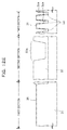
- FIG. 17 is a drawing obtained by experimentation utilizing threshold voltages of transfer transistors formed from each sample of FIG. 16 ;
- FIG. 18 is a graph obtained by experimentation of holding times of charges in cell capacitors formed from each sample of FIG. 16 ;
- FIG. 19A is a plan view illustrating the directions where an impurity is implanted in a second embodiment
- FIG. 19B is a sectional view schematically illustrating how to calculate the allowable range of a tilt angle at a twist angle of 0°;
- FIG. 20 is a plan view schematically illustrating a case where the tilt angle is set to be greater than 0° in the second embodiment
- FIGS. 21A and 21B are plan views schematically illustrating that word lines in a chip have two extending directions perpendicular to each other in the second embodiment
- FIG. 22 is a sectional view schematically illustrating design parameters used in the second embodiment
- FIG. 23 is a sectional view for calculating a maximum value estimated for a space between a word line and a resist pattern in the second embodiment
- FIG. 24 is a sectional view for calculating a minimum value estimated for a space between a side surface of the word line and a side surface of the resist pattern in the second embodiment.
- FIG. 25 is a sectional view schematically illustrating a case where the side surface of the resist pattern is positioned closer to the bit contact region than the center of the word line due to a positional misalignment in the second embodiment.
- FIG. 1 is a sectional view of the semiconductor device according to the preliminary matters.
- FIG. 1 illustrates part of the memory cell array region of the logic-mixed memory.
- the memory cell array region is roughly divided into a bit contact region I connected to bit lines and a storage region II where a cell capacitor C is formed.
- this semiconductor device includes a silicon substrate 1 on which an n-well 3 is formed.
- Word lines 5 a and a capacitor upper electrode 5 b are formed on the silicon substrate 1 via a gate insulating film 4 .
- the two word lines 5 a are formed in the memory cell array region, being spaced in parallel to each other.
- the word lines 5 a and the capacitor upper electrode 5 b are made of polysilicon.
- the word lines 5 a serves as a gate electrode of a transfer transistor TR.
- a source/drain extension 6 and a pocket region 7 are formed on the silicon substrate 1 of both sides thereof.
- the pocket region 7 is formed by ion-implanting, into the silicon substrate 1 , an n-type impurity which is the same conductive type impurity as that of an n-type channel region 2 of the transfer transistor TR.
- the source/drain extension 6 is formed by ion-implanting a p-type impurity.
- a sidewall spacer 8 is formed so as to cover the side surfaces of the word line 5 a and the capacitor upper electrode 5 b .
- a p-type source/drain region 9 connected to a bit line is formed on the silicon substrate 1 between the two word lines 5 a.
- the channel region 2 formed below the capacitor upper electrode 5 b serves as a lower electrode of the capacitor C, and the charges accumulated in the capacitor C are read by the transfer transistor TR.
- the pocket region 7 is formed so as to extend from both sides of the word line 5 a to below thereof, the roll-off phenomenon is hard to occur even if the gate length of the transfer transistor TR is reduced, allowing the threshold voltage of the transfer transistor TR to be maintained at a high level.
- the pocket region 7 is formed so as to extend from both the bit contact region I and the storage region II to below the word line 5 a by an oblique ion implantation where the ion implanting direction is oblique with respect to the substrate 1 .
- the pocket region 7 is not formed on the storage region II side in order to give priority to the charge holding time over the suppression of the roll-off phenomenon.
- FIG. 2 is a sectional view of the semiconductor device where the pocket region 7 on the bit contact region I side is formed and the pocket region on the storage region II side is omitted. It may be noted that the same reference numerals or characters as those of FIG. 1 are assigned to the components in FIG. 2 , and the description thereof is omitted.
- FIG. 3 is a sectional view illustrating the method of forming the pocket region 7 .
- a resist pattern 12 may be used to cover the storage region II on the silicon substrate 1 as illustrated in FIG. 3 .
- the pocket region 7 may be formed only on the bit contact region I side of both sides of the word line 5 a by ion-implanting an n-type impurity 11 obliquely into the silicon substrate 1 through a window 12 a of the resist pattern 12 .
- a positional misalignment may occur between the resist pattern 12 and the word line 5 a due to a manufacturing variation or the like.
- FIG. 4 is a sectional view illustrating a case where such a positional misalignment occurs.
- a positional misalignment occurs between the resist pattern 12 and the word line 5 a , and a space S is generated therebetween.
- shadowing effects by the word line 5 a may be obtained by a sufficiently large angle (implant angle) ⁇ between the vertical direction with respect to the surface of the silicon substrate 1 and the ion implanting direction, thereby preventing a pocket region 7 from being formed in the storage region II through the space S.
- the word line 5 a requiring the suppression of the roll-off phenomenon does not always extend in one direction on the silicon substrate 1 , and a plurality of word lines 5 a may extend in different directions depending on the type of the semiconductor device.
- FIGS. 5A and 5B are plan views schematically illustrating the word lines 5 a extending in different directions.
- the extending directions of the word lines 5 a are different by 90° in each of a first region A and a second region B.
- the implant angles for implanting an impurity below the word line 5 a are different for each of the regions A and B.
- FIGS. 6A and 6B are sectional views schematically illustrating such different implant angles.
- FIGS. 6A and 6B correspond to the sectional view near the word lines 5 a in each of the regions A and B of FIGS. 5A and 5B , respectively.
- the impurity 11 is ion-implanted below the word line 5 a at a predetermined implant angle ⁇ .
- the implant angle is 90° when viewed from the side of the silicon substrate 1 , and thus pocket implantation below the word line 5 a may not be performed.
- pocket implantation may not be performed for all the word lines 5 a at the same implant angle simply by performing an oblique ion implantation, and the characteristics fluctuate between the transistors.
- FIGS. 7A and 7B are plan views schematically illustrating a case where ion implantation is performed four times each from four different directions in order to achieve the same implant angle for the word lines 5 a in both regions A and B.
- the impurity 11 is ion-implanted into the silicon substrate 1 by changing the ion-implanting twist angle by 90°, starting at the extending direction of the word line 5 a in both regions A and B.
- FIGS. 8A and 8B are sectional views schematically illustrating such ion implantation.
- FIGS. 8A and 8B correspond to the sectional views near the word lines 5 a in each of the regions A and B of FIGS. 7A and 7B , respectively.
- the impurity 11 may be ion-implanted at a predetermined implant angle ⁇ in each of the regions A and B.
- the ion implanting angle becomes 90° when viewed from the side of the silicon substrate 1 .
- the sharp pn junction is formed between the n-type pocket region 7 and the p-type source/drain extension 6 on the storage region II side. Then, junction leakage due to the pn junction causes the charges in the capacitor C to leak to the substrate 1 side, thus reducing the holding time of the charges in the capacitor C.
- the present embodiment manufactures, as a semiconductor device, a logic-mixed memory where a logic region and a memory region are formed in one and same chip.
- FIG. 10 is a plan view illustrating a chip layout of the semiconductor device.
- the semiconductor device 20 includes a plurality of memory macros 21 , a logic region 22 and input/output sections 23 .
- each of the memory macros 21 is a design unit of a memory region, having a rectangular planar shape as illustrated in the figure.
- the semiconductor device 20 having a memory region according to the needs of the customer or the market may be obtained by arranging an appropriate number of the memory macros 21 in a chip.
- the method of arranging the memory macros 21 in the chip is not particularly limited, but the entire chip size may be reduced by arranging some of the memory macros 21 rotated by 90° from the others as illustrated in the figure.
- FIG. 11 is a plan view illustrating a plane layout of the memory macro 21 .
- the memory macro 21 has a predetermined number (e.g., 8) of a predetermined unit (e.g., 1 Mb) of memory cell array regions 25 as well as sense amplifiers 26 , a word decoder 27 , and an I/O address controller 28 .
- the word decoder 27 selects a cell in the memory cell array region 25 , and a memory signal read from the cell is amplified by the sense amplifier 26 . Then, the output from the sense amplifier 26 is amplified by a second amplifier 29 and then is inputted to the I/O address controller 28 .
- the I/O address controller 28 has a control circuit controlling, for example, a chip enable signal and a chip I/O signal.
- the word lines 45 a in the memory cell array region 25 are formed so as to extend in a predetermined direction in the memory macro 21 .
- groups of the word lines 45 a in the respective memory macros 21 extend in different directions.
- the word lines 45 a in the lower right memory macro 21 extend in a first direction D 1 in parallel to the horizontal direction on the paper, while the word lines 45 a in the upper left memory macro 21 extend in a second direction D 2 in parallel to the vertical direction on the paper, with the directions D 1 and D 2 being orthogonal to each other.
- FIGS. 12A to 12P are each a sectional view of a respective manufacturing process of the semiconductor device manufacturing method.
- FIG. 13A to 13G each are a plan view of a respective manufacturing process of the semiconductor device. Note that these sectional views and plan views correspond to some of the memory macros 21 illustrated in FIG. 10 , but the following processes are simultaneously performed on all the memory macros 21 .
- the surface of a silicon substrate 30 is thermally oxidized to form an initial oxide film 31 with a thickness of 5 to 20 nm.
- a silicon nitride film 32 is formed on the initial oxide film 31 .
- the film forming conditions of the silicon nitride film 32 are not particularly limited, but the present embodiment uses a thermal CVD method at a substrate temperature of 600 to 800° C. to form a thickness of 50 to 200 nm.
- FIG. 12A is sections along the A 1 -A 1 line, the B 1 -B 1 line, and the C 1 -C 1 line of FIG. 13A respectively.
- the A 1 -A 1 line and the B 1 -B 1 line are in parallel to the extending direction of the bit lines, and the C 1 -C 1 line is in parallel to the extending direction of the word line perpendicular to the bit lines.
- a first resist pattern 34 is formed by applying photoresist on the entire upper surface of the silicon substrate 30 , exposing and developing it.
- the silicon nitride film 32 , the initial oxide film 31 , and the silicon substrate 30 are dry-etched through a window 34 a of the first resist pattern 34 to form an element isolation trench 30 a with a depth of about 150 to 350 nm in the silicon substrate 30 .
- the silicon substrate 30 in a portion where the element isolation trench 30 a is not formed becomes an active region where an impurity diffused region such as a channel region will be formed by the subsequent process.
- the first resist pattern 34 used as a mask is removed by ashing, and a natural oxide film on the surface of the silicon substrate 30 is removed by hydrofluoric acid.
- SPM sulfuric acid/hydrogen Peroxide Mixture
- APM Ammonia/hydrogen Peroxide Mixture
- the element isolation trench 30 a is formed by using the first resist pattern 34 as the mask, but the first resist pattern 34 may be removed after the silicon nitride film 32 is dry-etched. In that case, the initial oxide film 31 and the silicon substrate 30 are dry-etched by using the silicon nitride film 32 as the mask.
- FIG. 13B is a plan view after the above process is finished, and each sectional view of the previous FIG. 12B corresponds to the sections along the A 2 -A 2 line, the B 2 -B 2 line, and the C 2 -C 2 line of FIG. 13B respectively.
- a silicon oxide film with a thickness of 300 to 500 nm is formed on the entire upper surface of the silicon substrate 30 as an element isolation insulating film 33 by an HDP (High Density Plasma) CVD method, and the element isolation trench 30 a is completely buried by the element isolation insulating film 33 .
- HDP High Density Plasma
- the element isolation insulating film 33 may be formed by a plasma CVD method using a TEOS gas instead of the HDP CVD method.
- a thermal oxide film with a thickness of about 2 to 10 nm may be formed by thermally oxidizing the inner surface.
- the element isolation insulating film 33 is polished by a CMP (Chemical Mechanical Polishing) method to leave the element isolation insulating film 33 in the element isolation trench 30 a.
- CMP Chemical Mechanical Polishing
- FIG. 13C is a plan view after the above process is finished, and each sectional view of the previous FIG. 12C corresponds to the sections along the A 3 -A 3 line, the B 3 -B 3 line, and the C 3 -C 3 line of FIG. 13C respectively.
- a second resist pattern 35 is formed by applying photoresist on the entire upper surface of the silicon substrate 30 , exposing and developing it.
- the element isolation insulating film 33 is dry-etched by using the second resist pattern 35 as the mask to form a trench 33 a in the element isolation insulating film 33 .
- the inner surface of the element isolation trench 30 a in the portion where the element isolation insulating film 33 is removed is exposed in the third section in parallel to the word line, and the element isolation insulating film 33 with a thickness of about 50 to 150 nm is left on the bottom surface of the element isolation trench 30 a.
- FIG. 13D is a plan view after the above process is finished, and each sectional view of the previous FIG. 12D corresponds to the sections along the A 4 -A 4 line, the B 4 -B 4 line, and the C 4 -C 4 line of FIG. 13D respectively.
- the second resist pattern 35 is removed by ashing.
- the silicon nitride film 32 is wet-etched by phosphoric acid, and further, the initial oxide film 31 thereunder is wet-etched by hydrofluoric acid and removed to expose a cleaning surface of the silicon substrate 30 in the active region. It may be noted that the silicon nitride film 32 may be etched by a mixed solution of phosphoric acid and hydrofluoric acid.
- the surface of the silicon substrate 30 is thermally oxidized again to form a sacrificial insulating film 36 with a thickness of 5 to 10 nm.
- n-well 37 P+ ions are implanted into the silicon substrate 30 as an n-type impurity to form an n-well 37 .
- the ion implanting conditions are not particularly limited.
- the present embodiment assumes an acceleration energy of 360 KeV, a dose amount of 7.5 ⁇ 10 12 cm ⁇ 2 , and a tilt angle of 7°.
- the twist angle is assumed to be set in four directions: 22°, 112°, 202°, and 292°.
- As+ ions are implanted twice into the silicon substrate 30 as an n-type impurity to form a channel region 38 on a surface portion of the silicon substrate 30 .
- the conditions for each ion implantation are as follows.
- the conditions for the first ion implantation is an acceleration energy of 100 KeV, a dose amount of 1.2 ⁇ 10 12 cm ⁇ 2 , and a tilt angle of 0°; and the conditions for the second ion implantation is an acceleration energy of 100 KeV, a dose amount of 3.5 ⁇ 10 12 cm ⁇ 2 , and a tilt angle of 7°.
- the sacrificial insulating film 36 used as the through-film is wet-etched by hydrofluoric acid and removed.
- the surface of the silicon substrate 30 is thermally oxidized to form a gate insulating film 40 with a thickness of 2 to 7 nm.
- the present process of thermally oxidization may be repeated for a predetermined number of times.
- a polysilicon film with a thickness of 70 to 150 nm is formed on each of the gate insulating film 40 and the element isolation insulating film 33 as a conductive film 45 by the CVD method.
- a p-type impurity such as boron may be selectively ion-implanted into the portion.
- a third resist pattern 43 is formed on the conductive film 45 , and the conductive film 45 is dry-etched by using the third resist pattern 43 as a mask.
- the word lines 45 a are formed in all the memory macros 21 in a chip illustrated in FIG. 10 , with the extending directions D 1 and D 2 being different depending on the memory macro 21 .
- a silicon oxide film and a silicon nitride film may be formed on the conductive film 45 as a hard mask, and the films may be dry-etched by using the hard mask as a mask.
- the third resist pattern 43 is removed by ashing, and then, the gate insulating film 40 in the portion not covered with the word line 45 a or the capacitor upper electrode 45 b is wet-etched by hydrofluoric acid and removed.
- FIG. 13E is a plan view after the above process is finished, and each sectional view of the previous FIG. 12I corresponds to the sections along the A 5 -A 5 line, the B 5 -B 5 line, and the C 5 -C 5 line of FIG. 13E respectively.
- a p-type impurity such as boron is ion-implanted into an active region of the silicon substrate 30 using the word line 45 a and the capacitor upper electrode 45 b as a mask.
- a p-type source/drain extension 46 is formed in the silicon substrate 30 at a side of each of the side surfaces 45 c and 45 d of the word line 45 a.
- the ion implanting conditions are, for example, an acceleration energy of 0.5 KeV, a dose amount of 5.0 ⁇ 10 13 cm ⁇ 2 , and a tilt angle of 0°.
- the twist angle is assumed to be set in four directions: 0°, 90°, 180°, and 270° starting at the extending direction of the word line 45 a.
- the ion-implantation uses a resist pattern covering the logic region 22 (see FIG. 10 ) as a mask, and after the ion-implantation is finished, the resist pattern is removed.
- a fourth resist pattern 47 is formed by applying photoresist with a thickness of about 0.32 ⁇ m on the entire upper surface of the silicon substrate 30 , exposing and developing it. After development, the thickness of the developed fourth resist pattern 47 decreases below the original thickness to about 0.295 ⁇ m.
- the fourth resist pattern 47 includes a side surface 45 c of the word line 45 a and a window 47 a where the bit contact region I of the silicon substrate 30 at the side of the side surface 45 c is exposed. Moreover, the fourth resist pattern 47 covers part of the upper surface of the word line 45 a and the storage region II of the silicon substrate 30 at the side of the other side surface 45 d of the word line 45 a.
- P+ ions are implanted into the active region of the silicon substrate 30 as an n-type impurity 48 the same conductive type as that of the channel region 38 using the fourth resist pattern 47 as a mask.
- a pocket region 49 is formed in the active region on the bit contact region I side.
- the tilt angle ⁇ is set to a value greater than 0° such as 30° so that the impurity 48 is implanted into the silicon substrate 30 from a direction inclined to the bit contact region I side from a direction n vertical to the surface of the silicon substrate 30 .
- the impurity 48 may be implanted below the word line 45 a , and thus the short channel effects below the word line 45 a may be easily suppressed.
- FIG. 12K is a sectional view of some of the plurality of memory macros 21 (see FIG. 10 ), but the other memory macros 21 rotated by 90° on the substrate have the same sectional view as that of FIG. 12K .
- the space S may be generated between the word line 45 a and the fourth resist pattern 47 due to a positional misalignment of the fourth resist pattern 47 .
- the impurity 48 is implanted into the silicon substrate 30 through the space S, and unfortunately, a pocket region 49 is also formed on the storage region II side. As described in the preliminary matters, if the pocket region 49 is formed on the storage region II side, there occurs a disadvantage of reducing the holding time of charges of a subsequently formed cell capacitor.
- the present embodiment uses the twist angle as illustrated in FIG. 14 to prevent the impurity 48 from being implanted into the space S.
- FIG. 14 is a plan view explaining the twist angle of the ion implantation.
- the present embodiment arranges a plurality of memory macros 21 by rotating some of them by 90° from the other memory macros 21 . Therefore, as illustrated in FIG. 14 , the extending directions D 1 and D 2 of the word line 45 a may be orthogonal to each other depending on the memory macro 21 .
- the impurity 48 when the pocket region 49 is formed, the impurity 48 is ion-implanted four times each by changing the twist angle. More specifically, at each ion implantation, the impurity 48 is implanted into the silicon substrate 30 from a direction oblique to the two directions D 1 and D 2 .
- the tilt angles ⁇ 1 to ⁇ 4 are defined each corresponding to the first to fourth ion implantation respectively, starting at the first direction D 1 .
- the twist angle ⁇ 1 of the first ion implantation is selected from the range 0° ⁇ 1 ⁇ 90° so that the implantation direction of the impurity 48 is oblique to each of the directions D 1 and D 2 .
- each of the other twist angles ⁇ 2 to ⁇ 4 is set so as to be larger by 90° than the previous twist angle.
- the twist angles ⁇ 1 to ⁇ 4 are set to 45°, 135°, 225°, and 325° respectively, and the ion implantation is performed each time with an acceleration energy of 30 KeV and a dose amount of 1.1 ⁇ 10 13 cm ⁇ 2 .
- the implantation direction of the impurity 48 is set to be oblique with respect to both the two directions D 1 and D 2 so as to prevent the impurity 48 from being implanted into the silicon substrate 30 below the space S in each of the memory macros 21 as described above.
- the pocket region 49 is formed in this manner, and then the fourth resist pattern 47 is removed.
- RTA Rapid Thermal Anneal
- a silicon oxide film with a thickness of about 30 to 80 nm is formed on the entire upper surface of the silicon substrate 30 as a sidewall insulating film 50 by the CVD method.
- the sidewall insulating film 50 is not limited to the silicon oxide film, but the sidewall insulating film 50 may be formed of a single layer silicon nitride film or a laminated film of a silicon oxide film and a silicon nitride film.
- photoresist is applied on the sidewall insulating film 50 , and then, exposed and developed to form a fifth resist pattern 51 .
- the sidewall insulating film 50 is dry-etched by using the fifth resist pattern 51 as a mask to form a sidewall spacer 50 a at each side of the word line 45 a and the capacitor upper electrode 45 b.
- the fifth resist pattern 51 is removed.
- a multilayer structured sidewall spacer 50 a may be formed by repeating the formation and etching of the sidewall insulating film 50 .
- FIG. 13F is a plan view after the above process is finished, and each sectional view of the previous FIG. 12M corresponds to the sections along the A 6 -A 6 line, the B 6 -B 6 line, and the C 6 -C 6 line of FIG. 13F respectively.
- the sidewall spacer 50 a and the word line 45 a are used as a mask to form a p-type source/drain region 53 by ion-implanting a p-type impurity into the silicon substrate 30 in the bit contact region I.
- a high melting point metal layer such as a cobalt layer and a nickel layer is formed on the entire upper surface of the silicon substrate 30 by a sputtering method, and then, is annealed and reacted with silicon to form a high melting point metallic silicide layer 55 . Then, an unreacted high melting point metal layer on the sidewall spacer 50 a and the like is removed by wet-etching to leave the high melting point metallic silicide layer 55 on the word line 45 a , the capacitor upper electrode 45 b , and the source/drain region 53 .
- the high melting point metallic silicide layer 55 assures low resistance of the word line 45 a and the like.
- a silicon oxide film is formed on the silicon substrate 30 as a first interlayer insulating film 56 by the CVD method. Then, the first interlayer insulating film 56 is patterned to form a contact hole 56 a on the source/drain region 53 . Note that although not illustrated, the contact hole 56 a is also formed on the end portion of the capacitor upper electrode 45 b.
- a contact plug 57 made mainly of tungsten is formed in a contact hole 56 a .
- a second interlayer insulating film 59 such as a silicon oxide film is formed on the upper surface of each of the contact plug 57 and the first interlayer insulating film 56 .
- a wiring groove is formed in the second interlayer insulating film 59 by photolithography, and a copper film is formed inside the wiring groove as a bit line 58 by a damascene method.
- FIG. 13G is a plan view after the above process is finished, and each sectional view of the previous FIG. 12P corresponds to the sections along the A 7 -A 7 line, the B 7 -B 7 line, and the C 7 -C 7 line of FIG. 13G respectively.
- the extending direction of the bit line 58 is orthogonal to the extending direction of the word line 45 a.
- the gate insulating film 40 under the capacitor upper electrode 45 b serves as a capacitor dielectric film of the cell capacitor C.
- the channel region 38 below the capacitor upper electrode 45 b serves as the lower electrode of the cell capacitor C.
- the word line 45 a also serves as a gate electrode of the transfer transistor TR, and the source/drain extension 46 on the storage region II side of the transfer transistor TR is electrically connected to the lower electrode of the cell capacitor C.
- FIG. 15 is an equivalent circuit diagram of the semiconductor device.
- a predetermined potential is given to the upper electrode 45 b of the cell capacitor C to put the channel region 38 thereunder in an ON state.
- the potential of the channel region 38 changes depending on whether the information written in the capacitor C is “1” or “0”. Therefore, the information written in the capacitor C may be read by reading the potential through the transfer transistor TR.
- the pocket region 49 is formed only in the silicon substrate 30 in the bit contact region I, and the pocket region 49 is not formed in the storage region II.
- the twist angle ⁇ 1 is selected so as to implant the impurity 48 obliquely with respect to both the first and second directions D 1 and D 2 which are extending directions of the word lines 45 a.
- the impurity 48 is implanted obliquely with respect to both the two directions D 1 and D 2 , which may suppress the impurity 48 from being implanted below the space S of each memory macro 21 , and may form the pocket region 49 only in the bit contact region I.
- FIG. 16 lists the process conditions of the samples used for this experiment.
- the samples A and B are for reference, and unlike the present embodiment, the pocket region 49 is formed on both sides of the word line 45 a . Note that when the pocket region 49 is formed, for the samples A and B, the twist angle is selected so as to be perpendicular or parallel to the extending direction of the word line.
- the pocket region 49 is formed only in the bit contact region I on a side of the word line 45 a . Moreover, when the pocket region 49 is formed, for the samples C and D, the twist angle is selected so as to be oblique with respect to the extending direction of the word line.
- the dose amount for the sample D is greater than that for the sample C.
- FIG. 17 is a drawing obtained by experimentation utilizing a threshold voltage Vth of the transfer transistor TR formed on each of the samples A to D under the aforementioned conditions. Note that this experiment was made on each of the plurality of transfer transistors TR formed on the silicon substrate 30 .
- the threshold voltage decreases by the short channel effects, and thus serves as one of the indicators to see whether or not the short channel effects is suppressed by the pocket region 49 .
- the threshold voltage thereof was higher than that of the reference samples A and B. Therefore, it is assumed that in the sample C, an n-type impurity was implanted in the pocket region 49 in high concentration and the pocket region 49 worked well in suppressing the short channel effects.
- the threshold voltage of the sample D was lower than that of the reference samples A and B. Therefore, it is assumed that in the sample D, the pocket region 49 did not worked very well in suppressing the short channel effects and the impurity concentration of the pocket region 49 was low. Such a low concentration provides a moderate pn junction between the p-type source/drain extension 46 and the n-type pocket region 49 , and thus there may be expected a longer holding time of the charges in the cell capacitor C.
- the experimental result is illustrated in FIG. 18 .
- the horizontal axis of FIG. 18 represents the holding time (Tref) of charges in an arbitrary unit. Note that the holding time in this experiment refers to the time from reading an amount of charge accumulated in a cell capacitor until reading next one.
- the vertical axis of FIG. 18 represents chip yield. In this experiment, it is assumed that the holding time (Tref) is 1 when the chip yield is 100%.
- the samples A and B, where the pocket region 49 is formed on both sides of the word line 45 a indicate that the yield decreases rapidly when the holding time becomes long. It may be considered that since the pocket region 49 is formed also on the storage region II side, leakage current occurs in the pn junction between the pocket region 49 and the source/drain extension 46 , which causes the charges to flow out of the cell capacitor C.
- the trend of decreasing yield is suppressed in the samples C and D according to the present embodiment, where the pocket region 49 is formed only on the bit contact region I side, and the twist angle is selected so as to be oblique with respect to the extending direction of the word line.
- the sample D exhibits the remarkable effects thereof.
- the pocket region 49 is formed only on the bit contact region I side, and an impurity of the pocket region 49 is implanted obliquely with respect to the extending direction of the word line, which are effective in increasing the holding time and in improving the refresh characteristics of the cell capacitor C.
- the tilt angle ⁇ is set to a value greater than 0°.
- the angles ⁇ 1 to ⁇ 4 are used so as to implant an impurity obliquely with respect to both the first and second directions D 1 and D 2 where the word lines 45 a extend.
- the pocket region 49 may be formed only in the bit contact region I which is a side of each of the two word lines 45 a , each extending in different directions.
- the present embodiment calculates the allowable range of the tilt angle ⁇ to prevent the impurity 48 from being implanted into the space S.
- FIG. 19A is a plan view illustrating the direction where the impurity 48 is implanted.
- the twist angle ⁇ is set to 0°.
- FIG. 19B is a sectional view schematically illustrating how to calculate the allowable range of the tilt angle ⁇ in the case of the twist angle ⁇ set to 0° in this manner.
- hRes denotes the height of the fourth resist pattern 47 and hWL denotes the height of the word line 45 a.
- W 1 denotes the width of the space S which occurs in the storage region II side due to a positional misalignment between the fourth resist pattern 47 and the word line 45 a .
- W 2 denotes the distance between the mutually facing side surfaces of the word line 45 a and the fourth resist pattern 47 .
- the minimum angle ⁇ 1 allowed for the tilt angle is a minimum tilt angle which may prevent the impurity 48 from being implanted into the silicon substrate 30 below the space S due to shadowing of the word line 45 a.
- the minimum angle ⁇ 1 is geometrically calculated by the following expression (1) from FIGS. 19A and 19B .
- the tilt angle in a range of the minimum angle ⁇ 1 or more by assuming the space S between the side surfaces of the word line 45 a and the fourth resist pattern 47 due to a manufacturing error such as a positional misalignment. This assures that at ion implantation, the shadow of the word line 45 a reaches the side surface of the fourth resist pattern 47 in the space S, and thus the impurity 48 is not implanted into the storage region II, thereby reducing the risk of unnecessarily forming the pocket region 49 in the storage region II.
- the maximum angle ⁇ 2 allowed for the tilt angle is a maximum tilt angle which allows the impurity 48 to be implanted into the bit contact region I at a side of the word line 45 a without being affected by the shadowing of the fourth resist pattern 47 .
- the maximum angle ⁇ 2 is geometrically calculated by the following expression (2) from FIG. 19B .
- the tilt angle is set in a range of the maximum angle ⁇ 2 or less, at ion implantation, the shadow of the fourth resist pattern 47 does not reach the side surface 45 c of the word line 45 a and thus the pocket region 49 may be formed so as to extend from the bit contact region I side to below the word line 45 a.
- W 1 and W 2 in FIG. 19B are equivalent to W 1 /cos ⁇ and W 2 /cos ⁇ respectively. Accordingly, the minimum angle ⁇ 1 and the maximum angle ⁇ 2 of the tilt angle are calculated by the following expressions (3) and (4) obtained from the expressions (1) and (2) respectively.
- the extending directions of the word lines 45 a in a chip have two mutually orthogonal directions D 1 and D 2 .
- the minimum angle is calculated by the expression (3) for each of the word lines 45 a extending in directions D 1 and D 2 , and the maximum value of them is used as the minimum angle ⁇ 1 of the tilt angle. Accordingly, the minimum angle ⁇ 1 is represented by the following expression (5).
- ⁇ ⁇ 1 max [ arctan ⁇ ( W 1 h WL ⁇ cos ⁇ ⁇ ⁇ ) , arctan ( W 1 h WL ⁇ cos ⁇ ( ⁇ 2 - ⁇ ) ) ] ( 5 )
- the maximum angle ⁇ 2 of the tilt angle is calculated by the expression (4) for each of the word lines 45 a extending in directions D 1 and D 2 , and the minimum value of them may be calculated by the following expression (6).
- the tilt angle ⁇ in a range ⁇ 1 ⁇ 2 in order to insure the manufacturing margin by considering manufacturing variations of the ion implanting directions.
- the minimum angle ⁇ 1 and the maximum angle ⁇ 2 of the tilt angle are calculated.
- W 3 denotes the width of the window 47 a of the fourth resist pattern 47 ; and L 1 denotes the gate length of the word line 45 a . Further, L 3 denotes the length of the overlapped portion of the word line 45 a and the fourth resist pattern 47 ; and L 2 denotes the length of a portion of the word line 45 a which portion is exposed to the window 47 a.
- FIG. 22 assumes a design arrangement where there is no positional misalignment between the fourth resist pattern 47 and the word line 45 a.
- L 2 is not equal to L 3 . More specifically, the side surface 47 b of the fourth resist pattern 47 is shifted closer to the storage region II side from the center of the word line 45 a . This is to surely form the pocket region 49 below the word line 45 a by preventing the word line 45 a from being completely covered with the fourth resist pattern 47 even if a positional misalignment of the fourth resist pattern 47 occurs.
- the fourth resist pattern 47 may be shifted right or left as a whole with respect to the word line 45 a , or the width W 3 of the window 47 a may be greater than the design value.
- the positional misalignment of the fourth resist pattern 47 in the horizontal direction is typically about 0.04 ⁇ m.
- FIG. 23 is a sectional view for calculating a maximum value estimated for the width W 1 of the space S. The maximum value is used to calculate the minimum angle ⁇ 1 of the tilt angle.
- the gate length L 1 of the word line 45 a is assumed to be 0.084 ⁇ m, which is smaller by a maximum thin width (0.006 ⁇ m) estimated in manufacturing than a target value of 0.09 ⁇ m.
- the side surface of the word line 45 a is farther by 0.006/2 ⁇ m from the side surface of the fourth resist pattern 47 in the space S.
- the positional misalignment of the fourth resist pattern 47 with respect to the word line 45 a is expected to be 0.044 ⁇ m. Therefore, the side surface of the word line 45 a is farther by 0.044 ⁇ m+0.006/2 ⁇ m from the side surface of the fourth resist pattern 47 in the space S.
- the overlapped length L 3 of the third resist pattern 43 and the word line 45 a is 0.03 ⁇ m as the target value, and thus the maximum value estimated for the width W 1 of the space S is 0.017 ⁇ m (0.044 ⁇ m+0.006/2 ⁇ m ⁇ 0.03 ⁇ m).
- FIG. 24 is a sectional view for calculating a minimum value estimated for distance W 2 .
- the minimum value is used to calculate the maximum angle ⁇ 2 of the tilt angle.
- the gate length L 1 of the word line 45 a is assumed to be 0.096 ⁇ m, which is larger by a maximum thick width (0.006 ⁇ m) estimated in manufacturing than a target value of 0.09 ⁇ m.
- the distance W 2 becomes smaller by 0.006/2 ⁇ m.
- the decrease of the distance W 2 includes the above calculated amount (0.044 ⁇ m) of the positional misalignment of the fourth resist pattern 47 with respect to the word line 45 a.
- the minimum value of the distance W 2 becomes 0.213 ⁇ m which is obtained by subtracting the above sum of 0.006/2 ⁇ m and 0.044 ⁇ m from the sum of the design value (0.20 ⁇ m) of the distance W 4 between the adjacent word lines 45 a and the design value (0.06 ⁇ m) of the length L 2 .
- FIG. 25 is a sectional view illustrating a case where the side surface 47 b of the fourth resist pattern 47 is positioned closer to the bit contact region I than the center of the word line 45 a due to a positional misalignment of the fourth resist pattern 47 and the decrease in the gate length L 1 of the word line 45 a.
- the length L 3 becomes smaller than the design value of 0.06 ⁇ m.
- the pocket region 49 may be formed below the word line 45 a without the fourth resist pattern 47 falling off from the upper surface of the word line 45 a to the bit contact region I side.
- the maximum value estimated for the width W 1 of the space S is 0.017 ⁇ m; and the minimum value estimated for the distance W 2 is 0.213 ⁇ m.
- the minimum angle ⁇ 1 and the maximum angle ⁇ 2 of the tilt angle ⁇ are determined as the following expression (7) obtained by expressions (5) and (6).
- the tilt angle ⁇ may be within the range of the expression (7) allowing for some degrees from the minimum angle ⁇ 1 and the maximum angle ⁇ 2 .
- the twist angle ⁇ 1 of 45° and the tilt angle of 30° under the conditions described in the first embodiment satisfy the expression (7). Therefore, even if a positional misalignment or the like of the fourth resist pattern 47 occurs, the impurity 48 is not implanted into the silicon substrate 30 below the space S, and thus the pocket region 49 may be formed only on the bit contact region I side.
Landscapes
- Engineering & Computer Science (AREA)
- Power Engineering (AREA)
- Manufacturing & Machinery (AREA)
- Physics & Mathematics (AREA)
- Condensed Matter Physics & Semiconductors (AREA)
- General Physics & Mathematics (AREA)
- Computer Hardware Design (AREA)
- Microelectronics & Electronic Packaging (AREA)
- Semiconductor Memories (AREA)
- Metal-Oxide And Bipolar Metal-Oxide Semiconductor Integrated Circuits (AREA)
Abstract
Description
Claims (12)
Applications Claiming Priority (2)
| Application Number | Priority Date | Filing Date | Title |
|---|---|---|---|
| JP2008306677A JP5381053B2 (en) | 2008-12-01 | 2008-12-01 | Manufacturing method of semiconductor device |
| JP2008-306677 | 2008-12-01 |
Publications (2)
| Publication Number | Publication Date |
|---|---|
| US20100136758A1 US20100136758A1 (en) | 2010-06-03 |
| US7776659B2 true US7776659B2 (en) | 2010-08-17 |
Family
ID=42223195
Family Applications (1)
| Application Number | Title | Priority Date | Filing Date |
|---|---|---|---|
| US12/627,941 Expired - Fee Related US7776659B2 (en) | 2008-12-01 | 2009-11-30 | Semiconductor device manufacturing method |
Country Status (2)
| Country | Link |
|---|---|
| US (1) | US7776659B2 (en) |
| JP (1) | JP5381053B2 (en) |
Families Citing this family (5)
| Publication number | Priority date | Publication date | Assignee | Title |
|---|---|---|---|---|
| US7846821B2 (en) * | 2008-02-13 | 2010-12-07 | Icemos Technology Ltd. | Multi-angle rotation for ion implantation of trenches in superjunction devices |
| JP6280747B2 (en) | 2014-01-14 | 2018-02-14 | 三重富士通セミコンダクター株式会社 | Semiconductor integrated circuit device and manufacturing method thereof |
| US10892008B2 (en) * | 2018-06-15 | 2021-01-12 | Taiwan Semiconductor Manufacturing Company, Ltd. | Multi word line assertion |
| US11101353B2 (en) * | 2019-04-17 | 2021-08-24 | Taiwan Semiconductor Manufacturing Company, Ltd. | Semiconductor device and method of manufacture |
| CN111627803B (en) * | 2020-06-11 | 2022-08-09 | 上海华虹宏力半导体制造有限公司 | Device test structure, manufacturing method and test method thereof |
Citations (5)
| Publication number | Priority date | Publication date | Assignee | Title |
|---|---|---|---|---|
| JP2001077361A (en) | 1999-09-08 | 2001-03-23 | Hitachi Ltd | Semiconductor integrated circuit device and its manufacturing method |
| US20040007729A1 (en) | 2002-07-15 | 2004-01-15 | Koichi Kokubun | Semiconductor device and manufacturing method thereof |
| JP2004095385A (en) | 2002-08-30 | 2004-03-25 | Sumitomo Osaka Cement Co Ltd | Method of manufacturing positive electrode material for lithium ion battery and lithium ion battery |
| US20060009035A1 (en) * | 2003-11-17 | 2006-01-12 | Micron Technology, Inc. | Method for forming polysilicon local interconnects |
| JP2006147768A (en) | 2004-11-18 | 2006-06-08 | Toshiba Corp | Semiconductor device and its manufacturing method |
Family Cites Families (4)
| Publication number | Priority date | Publication date | Assignee | Title |
|---|---|---|---|---|
| US6444548B2 (en) * | 1999-02-25 | 2002-09-03 | International Business Machines Corporation | Bitline diffusion with halo for improved array threshold voltage control |
| JP2001176984A (en) * | 1999-12-22 | 2001-06-29 | Hitachi Ltd | Method for producing semiconductor integrated circuit device |
| JP3831277B2 (en) * | 2001-12-28 | 2006-10-11 | 株式会社東芝 | Semiconductor device |
| DE10248723A1 (en) * | 2002-10-18 | 2004-05-06 | Infineon Technologies Ag | Integrated circuit arrangement with capacitors and preferably planar transistors and manufacturing processes |
-
2008
- 2008-12-01 JP JP2008306677A patent/JP5381053B2/en not_active Expired - Fee Related
-
2009
- 2009-11-30 US US12/627,941 patent/US7776659B2/en not_active Expired - Fee Related
Patent Citations (6)
| Publication number | Priority date | Publication date | Assignee | Title |
|---|---|---|---|---|
| JP2001077361A (en) | 1999-09-08 | 2001-03-23 | Hitachi Ltd | Semiconductor integrated circuit device and its manufacturing method |
| US20040007729A1 (en) | 2002-07-15 | 2004-01-15 | Koichi Kokubun | Semiconductor device and manufacturing method thereof |
| JP2004047905A (en) | 2002-07-15 | 2004-02-12 | Toshiba Corp | Semiconductor device and its manufacturing method |
| JP2004095385A (en) | 2002-08-30 | 2004-03-25 | Sumitomo Osaka Cement Co Ltd | Method of manufacturing positive electrode material for lithium ion battery and lithium ion battery |
| US20060009035A1 (en) * | 2003-11-17 | 2006-01-12 | Micron Technology, Inc. | Method for forming polysilicon local interconnects |
| JP2006147768A (en) | 2004-11-18 | 2006-06-08 | Toshiba Corp | Semiconductor device and its manufacturing method |
Non-Patent Citations (1)
| Title |
|---|
| Y. Matsubara et al, "Fully Compatible Integration of High Density Embedded DRAM with 65nm CMOS Technology (CMOS5)", Electron Device Meeting, 2003, IEDM 2003 Technical Digest, IEEE International, Dec. 8-10, 2003, pp. 17.5.1-17.5.4. |
Also Published As
| Publication number | Publication date |
|---|---|
| JP5381053B2 (en) | 2014-01-08 |
| JP2010129980A (en) | 2010-06-10 |
| US20100136758A1 (en) | 2010-06-03 |
Similar Documents
| Publication | Publication Date | Title |
|---|---|---|
| US9443991B2 (en) | Semiconductor device and method of manufacturing the same | |
| JP4927321B2 (en) | Semiconductor memory device | |
| US7772053B2 (en) | Method for fabrication of semiconductor device | |
| US20080050875A1 (en) | Methods of fabricating embedded flash memory devices | |
| JP2006351987A (en) | Nonvolatile semiconductor device and its manufacturing method | |
| JP2007081335A (en) | Semiconductor device | |
| US6303432B1 (en) | Method of manufacturing a semiconductor device | |
| US7776659B2 (en) | Semiconductor device manufacturing method | |
| KR100486187B1 (en) | Semiconductor device and its manufacturing method | |
| US10411018B2 (en) | SRAM memory cell and SRAM memory with conductive interconnect | |
| US10170597B2 (en) | Method for forming flash memory unit | |
| CN115295494A (en) | Manufacturing method of semiconductor structure | |
| US20070057303A1 (en) | Method For Forming Trench Capacitor and Memory Cell | |
| US20090098695A1 (en) | Differential offset spacer | |
| US8530960B2 (en) | Semiconductor device | |
| JP5432379B2 (en) | Semiconductor device | |
| KR101498170B1 (en) | Semiconductor memory device and method of fabricating the same | |
| JP5861196B2 (en) | Semiconductor device | |
| US6790735B2 (en) | Method of forming source/drain regions in semiconductor devices | |
| US9437598B2 (en) | Semiconductor device manufacturing method and semiconductor device | |
| JP2013258436A (en) | Method for manufacturing semiconductor device | |
| US7977723B2 (en) | Semiconductor device | |
| JP5725679B2 (en) | Semiconductor device | |
| US20150371992A1 (en) | Semiconductor device and method of manufacturing the same | |
| JP2006216838A (en) | Semiconductor device |
Legal Events
| Date | Code | Title | Description |
|---|---|---|---|
| AS | Assignment |
Owner name: FUJITSU MICROELECTRONICS LIMITED,JAPAN Free format text: ASSIGNMENT OF ASSIGNORS INTEREST;ASSIGNORS:OGAWA, HIROYUKI;KOJIMA, HIDEYUKI;SIGNING DATES FROM 20091125 TO 20091127;REEL/FRAME:023593/0096 Owner name: FUJITSU MICROELECTRONICS LIMITED, JAPAN Free format text: ASSIGNMENT OF ASSIGNORS INTEREST;ASSIGNORS:OGAWA, HIROYUKI;KOJIMA, HIDEYUKI;SIGNING DATES FROM 20091125 TO 20091127;REEL/FRAME:023593/0096 |
|
| AS | Assignment |
Owner name: FUJITSU SEMICONDUCTOR LIMITED, JAPAN Free format text: CHANGE OF NAME;ASSIGNOR:FUJITSU MICROELECTRONICS LIMITED;REEL/FRAME:024651/0744 Effective date: 20100401 |
|
| STCF | Information on status: patent grant |
Free format text: PATENTED CASE |
|
| FEPP | Fee payment procedure |
Free format text: PAYOR NUMBER ASSIGNED (ORIGINAL EVENT CODE: ASPN); ENTITY STATUS OF PATENT OWNER: LARGE ENTITY |
|
| FPAY | Fee payment |
Year of fee payment: 4 |
|
| AS | Assignment |
Owner name: FUJITSU SEMICONDUCTOR LIMITED, JAPAN Free format text: CHANGE OF ADDRESS;ASSIGNOR:FUJITSU SEMICONDUCTOR LIMITED;REEL/FRAME:041188/0401 Effective date: 20160909 |
|
| MAFP | Maintenance fee payment |
Free format text: PAYMENT OF MAINTENANCE FEE, 8TH YEAR, LARGE ENTITY (ORIGINAL EVENT CODE: M1552) Year of fee payment: 8 |
|
| AS | Assignment |
Owner name: AIZU FUJITSU SEMICONDUCTOR LIMITED, JAPAN Free format text: ASSIGNMENT OF ASSIGNORS INTEREST;ASSIGNOR:FUJITSU SEMICONDUCTOR LIMITED;REEL/FRAME:053209/0468 Effective date: 20200331 |
|
| AS | Assignment |
Owner name: FUJITSU SEMICONDUCTOR LIMITED, JAPAN Free format text: CHANGE OF NAME AND CHANGE OF ADDRESS;ASSIGNOR:AIZU FUJITSU SEMICONDUCTOR LIMITED;REEL/FRAME:053481/0962 Effective date: 20200410 |
|
| FEPP | Fee payment procedure |
Free format text: MAINTENANCE FEE REMINDER MAILED (ORIGINAL EVENT CODE: REM.); ENTITY STATUS OF PATENT OWNER: LARGE ENTITY |
|
| LAPS | Lapse for failure to pay maintenance fees |
Free format text: PATENT EXPIRED FOR FAILURE TO PAY MAINTENANCE FEES (ORIGINAL EVENT CODE: EXP.); ENTITY STATUS OF PATENT OWNER: LARGE ENTITY |
|
| STCH | Information on status: patent discontinuation |
Free format text: PATENT EXPIRED DUE TO NONPAYMENT OF MAINTENANCE FEES UNDER 37 CFR 1.362 |
|
| FP | Lapsed due to failure to pay maintenance fee |
Effective date: 20220817 |