US7774587B2 - Dynamic redundancy checker against fault injection - Google Patents
Dynamic redundancy checker against fault injection Download PDFInfo
- Publication number
- US7774587B2 US7774587B2 US11/486,232 US48623206A US7774587B2 US 7774587 B2 US7774587 B2 US 7774587B2 US 48623206 A US48623206 A US 48623206A US 7774587 B2 US7774587 B2 US 7774587B2
- Authority
- US
- United States
- Prior art keywords
- memory
- signature
- checker
- data
- address
- Prior art date
- Legal status (The legal status is an assumption and is not a legal conclusion. Google has not performed a legal analysis and makes no representation as to the accuracy of the status listed.)
- Expired - Fee Related, expires
Links
Images


Classifications
-
- G—PHYSICS
- G06—COMPUTING; CALCULATING OR COUNTING
- G06F—ELECTRIC DIGITAL DATA PROCESSING
- G06F11/00—Error detection; Error correction; Monitoring
- G06F11/07—Responding to the occurrence of a fault, e.g. fault tolerance
- G06F11/08—Error detection or correction by redundancy in data representation, e.g. by using checking codes
- G06F11/10—Adding special bits or symbols to the coded information, e.g. parity check, casting out 9's or 11's
- G06F11/1008—Adding special bits or symbols to the coded information, e.g. parity check, casting out 9's or 11's in individual solid state devices
-
- G—PHYSICS
- G06—COMPUTING; CALCULATING OR COUNTING
- G06F—ELECTRIC DIGITAL DATA PROCESSING
- G06F21/00—Security arrangements for protecting computers, components thereof, programs or data against unauthorised activity
- G06F21/50—Monitoring users, programs or devices to maintain the integrity of platforms, e.g. of processors, firmware or operating systems
- G06F21/52—Monitoring users, programs or devices to maintain the integrity of platforms, e.g. of processors, firmware or operating systems during program execution, e.g. stack integrity ; Preventing unwanted data erasure; Buffer overflow
-
- G—PHYSICS
- G11—INFORMATION STORAGE
- G11C—STATIC STORES
- G11C29/00—Checking stores for correct operation ; Subsequent repair; Testing stores during standby or offline operation
- G11C29/04—Detection or location of defective memory elements, e.g. cell constructio details, timing of test signals
- G11C2029/0409—Online test
Definitions
- the present invention relates to computer systems and more particularly to a method and system for checking for fault injection.
- Secure microcontrollers and other similar computers systems may be subject to external attack. Such attacks typically aim to control circuit behavior and extract sensitive information. Because program memories are easy to localize on silicon and are typically important to the security of the system, program memories are also typically targets of external attack. Consequently, conventional methods for protecting such memories are used to protect against such attacks.
- FIG. 1 depicts a conventional computer system 10 , such as a microcontroller, that is protected against external attacks in a conventional manner.
- the conventional computer system 10 is depicted as including a conventional system central processing unit (CPU) 12 , a conventional program memory 14 , and a conventional checker 20 that outputs a strategy 26 . Although only these components are depicted, the conventional computer system 10 typically includes other components that, for clarity, are not shown.
- the conventional program memory 14 is depicted as included a conventional word 16 and a corresponding parity bit 18 .
- the program memory data output includes n-bit data word 16 and a corresponding parity bit 18 which is calculated for each program memory location and stored at the same memory address.
- the n-bit data word typically includes CPU instructions which are stored to be fetched at some later time by the CPU 12 .
- the conventional checker 20 includes a conventional parity bit calculator 22 and a NAND gate 24 .
- FIG. 2 depicts a conventional method 50 for protecting the conventional computer system 10 .
- a corresponding parity bit 18 is calculated, via step 52 .
- the conventional word 16 is stored in one location in the conventional program memory 14 while the corresponding parity bit 18 is also separately stored in the program memory 16 , via step 54 .
- the conventional computer system 10 separately provides the conventional word 16 and the parity bit to the checker 20 , via step 56 .
- a parity bit is determined from the conventional word 16 using the parity bit calculator 22 , via step 58 .
- the parity bit calculated from the conventional word 16 is compared to the corresponding parity bit 18 preferably using the NAND gate 24 , via step 60 . Based on the comparison, a security strategy 26 may be provided, via step 62 . If the comparison performed in step 60 indicates that the parity bits match, then the security strategy 26 may simply include providing the instructions or other data corresponding to the conventional word 16 from the conventional program memory 14 to the conventional system CPU 12 . However, if the comparison indicates that the parity bits do not match, then the security strategy 26 may include other actions. For example, a security interrupt, a security reset, or other operation may be performed.
- the conventional method 50 provides some protection for the conventional system 10
- the conventional method 50 has some drawbacks.
- the use of the parity bit 18 conventional checker 20 does not detect more than a single bit error. Thus, other errors may not be distinguished.
- use of the parity bit 18 requires storage of one bit per word 16 . Consequently, the size of the entire conventional program memory 14 is increased.
- the present invention provides a method and system for checking data stored in a memory of in a computer system.
- the memory includes a plurality of memory addresses.
- the method and system comprise providing a signature generator coupled with the memory, providing a checker memory coupled with the signature generator and separate from the memory, and providing an address remapper coupled with the checker memory and the memory.
- the signature generator provides at least one signature corresponding to the data, which resides in a protection window of the memory.
- the protection window includes at least one memory address of the plurality of memory addresses.
- the checker memory stores the at least one signature in at least one checker address, which corresponds to the at least one memory address.
- the address remapper for translates between the at least one memory address and the at least one checker address
- the present invention may provide an improved method for protecting the data against external attack.
- FIG. 1 is diagram depicting a system for protecting data in a computer system.
- FIG. 2 is a diagram of a conventional method for checking data in a computer system.
- FIG. 3 is a diagram one embodiment of a system in accordance with the present invention for protecting data in a computer system.
- FIG. 4 is a diagram of one embodiment of an architecture in accordance with the present invention for filling the checker memory in protecting data in a computer system.
- FIG. 5 is a flow chart depicting one embodiment of a method in accordance with the present invention for filling the checker memory in protecting data in a computer system.
- FIG. 6 is a diagram of one embodiment of an architecture in accordance with the present invention for checking data in a computer system.
- FIG. 7 is a flow chart depicting one embodiment of a method in accordance with the present invention for checking data in a computer system.
- FIG. 8 is a diagram of another embodiment of a system in accordance with the present invention for protecting data in a computer system.
- the present invention relates to protection of data in computer systems.
- the following description is presented to enable one of ordinary skill in the art to make and use the invention and is provided in the context of a patent application and its requirements.
- Various modifications to the preferred embodiments and the generic principles and features described herein will be readily apparent to those skilled in the art.
- the present invention is not intended to be limited to the embodiments shown, but is to be accorded the widest scope consistent with the principles and features described herein.
- the present invention provides a method and system for checking data stored in a memory of in a computer system.
- the memory includes a plurality of memory addresses.
- the method and system comprise providing a signature generator coupled with the memory, providing a checker memory coupled with the signature generator and separate from the memory, and providing an address remapper coupled with the checker memory and the memory.
- the signature generator provides at least one signature corresponding to the data, which resides in a protection window of the memory.
- the protection window includes at least one memory address of the plurality of memory addresses.
- the checker memory stores the at least one signature in at least one checker address, which corresponds to the at least one memory address.
- the address remapper for translates between the at least one memory address and the at least one checker address.
- the present invention will be described in terms of a computer system having particular components. However, one of ordinary skill in the art will readily recognize that the method and system in accordance with the present invention may utilize other components consistent with the present invention. Moreover, the present invention is described primarily in the context of a single protection window in a memory. However, one of ordinary skill in the art will recognize that the method and system function with multiple protection windows. In addition, although the method in accordance with the present invention is described in the context of methods having a certain number of steps that are described as proceeding in a particular order, one of ordinary skill in the art will recognize that multiple steps might be performed in parallel. Furthermore, for clarity, steps and components may be omitted. In addition, the system and method are described in the context of single components, such as a single signature generator, address remapper, and signature checker. However, one of ordinary skill in the art will recognize the multiple ones of such components may be utilized.
- FIG. 3 is a diagram one embodiment of a system in accordance with the present invention for protecting data in a computer system.
- the computer system 100 includes a central processing unit (CPU) 104 that is desired to be kept secure against external attack as well as a program bus 102 .
- the computer system 100 also includes a memory 110 , a signature generator 120 , a dedicated checker memory 130 , an address remapper 140 , and a signature checker 150 that provides a security strategy 160 .
- the memory 110 is preferably a program memory that stores instructions.
- the data within the memory 110 that is desired to be protected resides within the protection window 112 .
- the protection window 112 is bounded by addresses 114 and 116 .
- the memory 110 preferably stores instructions for the CPU 104 desired to be kept secure. Note that although the system 100 is described in the context of having a single protection window 112 , the system 100 can operate effectively with multiple program windows.
- the signature generator 120 generates signatures corresponding to the data in the protection window 112 and provides the signatures to the checker memory 130 .
- the address remapper 140 translates between addresses in the memory 110 (memory addresses) and addresses in the checker memory 130 (checker addresses).
- the checker memory 130 is a dedicated memory separate from the memory 100 storing data to be protected.
- the checker memory 130 is a random access memory (RAM).
- the signature checker 150 includes a signature calculator 152 and a comparison block 154 that is preferably a comparator represented by the NAND gate 154 .
- the signature checker 150 computes signatures based upon the data from the protection window 112 and compares the calculated signature to the corresponding signatures stored in the checker memory 130 . Based upon this comparison, the signature checker 150 outputs a security strategy 160 .
- the security strategy 160 preferably allows the CPU 104 to execute the instructions if the calculated signatures match the signatures stored in the checker memory 130 .
- the signature checker 150 provides a security strategy 160 , such as an internal security reset of a security interrupt if the calculated signatures do not match.
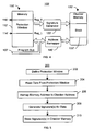
- FIG. 4 is a diagram of one embodiment in accordance with the present invention of an architecture 100 ′ for filling the checker memory in protecting data in a computer system.
- FIG. 5 is a flow chart depicting one embodiment of a method 200 in accordance with the present invention for filling the checker memory in protecting data in a computer system.
- the architecture 100 ′ includes portions of the computer system 100 .
- the architecture 100 ′ depicts program address bus 102 ′, the memory 110 ′ that is preferably a program memory, signature generator 120 ′, checker memory 130 ′ that is preferably a RAM, and address remapper 140 ′.
- These components 102 ′, 110 ′, 120 ′, 130 ′ and 140 ′ perform analogous functions to the components 102 ′, 110 , 120 , 130 , and 140 , respectively.
- the protection window 112 ′ is defined, via step 202 .
- Step 202 is preferably performed by a software developer defining the memory addresses 114 ′ and 116 ′ (registers Reg_L and Reg_H, respectively) as the boundaries of the window.
- the memory addresses 114 ′ and 116 ′ define the low and high memory addresses of the protection window 112 ′.
- step 202 might be repeated to change the size of the protection window 112 ′ and/or the data protected by the system 100 ′.
- the program instructions desired to be protected might be changed.
- Step 204 preferably includes reading address by address the n-bit data words stored in each memory address.
- the memory addresses in the protection window 112 ′ are remapped to checker memory addresses in the checker memory 130 ′ using the address remapper 140 ′, via step 206 .
- each memory address in the protection window 112 ′ has a single corresponding checker memory address in the checker memory 130 ′.
- the memory addresses 114 ′ through 116 ′ are thus preferably remapped to a block 132 ′ in the checker memory 130 ′.
- the address 114 (Reg_L) of the protection window could be associated with a first address (e.g.
- the maximum length of the protection window is less than or equal to the length of the block in the checker memory 130 ′ that is associated with that protection window 112 ′.
- the address could also be scrambled by the address remapper 140 in step 206 .
- the address scrambling could also be performed before or after address translation by the address remapper 140 / 140 ′ so that filling of the checker memory 130 / 130 ′/ 130 ′′ using the method 200 is more robust.
- Signatures corresponding to the data in the protection window 112 ′ are generated using the signature generator 120 ′, via step 208 .
- an m-bit signature is generated for each n-bit data word read in step 202 .
- the parameter m is an indicator of the size of the checker memory 130 ′, the hardware costs, and the robustness of the protection provided.
- the signature provided might correspond to the parity bit function, have a low hardware (checker memory 130 ′) cost, but have less robust fault coverage.
- the signatures are stored in the checker memory 130 , via step 210 .
- Step 210 includes storing the m-bit signatures in the checker memory addresses determined in step 206 .
- the sequence indicated in steps 204 , 206 , 208 , and 210 is commenced by a user accessing a control register. Also in a preferred embodiment, this sequence is performed address by address, word by word. Thus, a word is read from a particular address in the protection window 112 ′ in step 204 . The memory address is remapped to a checker memory address, the signature for this word is preferably determined, and the signature stored in a corresponding memory address in the checker memory 130 ′ on the fly in steps 206 , 208 and 210 , respectively.
- a hardware direct memory access (DMA) operation could be used to increase the speed of the method 200 .
- the steps 204 , 206 , 208 , and 210 are preferably performed during a CPU WAIT state to avoid any attempt by the CPU 104 to access the protection window 112 ′. Filling the checker memory 130 / 130 ′ using the steps 204 , 206 , 208 , and 210 could be performed during resets on a default area.
- a memory 110 / 110 ′ having a width of 2n might be used to improve the efficiency of the method 200 in terms of area and performance.
- FIG. 6 is a diagram of one embodiment in accordance with the present invention an architecture 100 ′′ for checking data in a computer system.
- FIG. 7 is a flow chart depicting one embodiment of a method 250 in accordance with the present invention for checking data in a computer system.
- the architecture 100 ′′ includes portions of the computer system 100 .
- the architecture 100 ′′ depicts program address bus 102 ′′, the system CPU 104 ′, the memory 110 ′′ that is preferably a program memory, checker memory 130 ′′ that is preferably a RAM, address remapper 140 ′′, signature checker 150 ′ and security strategy 160 ′.
- components 102 ′′, 104 ′, 110 ′′, 130 ′′, 140 ′′, 150 ′, and 160 ′ perform analogous functions to the components 102 , 104 , 110 , 120 , 130 , 140 , 150 , and 160 , respectively.
- the address remapper 140 ′/ 140 ′′ is preferably used both in filling the checker memory 130 ′/ 130 ′′ and when program instructions are to be read and checked.
- the address remapper 140 ′ could be different from the address remapper 140 ′′.
- step 252 includes receiving in the memory 110 ′′ and the address remapper 140 ′′ the memory addresses to be read from the memory 110 ′′. Note that if a particular memory address is outside the protection window 112 ′′, for example due to a branch/jump or an interrupt, the method 250 simply does not proceed from step 252 . When a memory address again is within the protection window, the method 250 recommences. For addresses in the protection window, these addresses are translated to checker memory addresses in the checker memory 130 ′′ using the address remapper 140 ′′, via step 254 .
- checker memory addresses are read from the checker memory 130 ′′ to obtain the signatures corresponding to the requested data, via step 256 .
- the signatures are provided to the signature checker 150 ′.
- the corresponding m-bit signatures are preferably provided to the signature checker 150 ′.
- the data (e.g. program instructions) in the memory addresses of the protection window 112 ′ are also read and provided to the signature checker 150 ′, via step 258 .
- the n-bit word is provided to the signature checker 150 ′.
- the data are preferably provided to the CPU 104 ′. From the data, signatures are calculated using the signature calculator 152 ′, via step 260 . Calculated signatures are thus generated.
- Step 262 preferably includes comparing each signature bit by bit. Based on this comparison, a security strategy 160 ′ may be output, via step 264 . If the signatures match, then the security strategy 160 ′ preferably simply allows the CPU 104 ′ to continue to use the data (execute the instructions) already fetched. If the signatures do not match, then the security strategy preferably includes a security interrupt, security reset, or other mechanism that interrupts use of the data (execution of the instructions).
- the sequence indicated in steps 252 , 254 , 256 , 258 , 260 , 262 , and 264 is performed address by address, word by word.
- a particular memory address in the protection window 112 ′ is received and translated to a corresponding checker memory address in steps 252 and 254 .
- the m-bit signature at this checker memory address and the n-bit data word at the memory address in the program window 112 ′′ are read in steps 256 and 258 , respectively.
- the calculated m-bit signature is generated from the n-bit data word in step 260 .
- the calculated m-bit signature is compared to the m-bit signature from the checker memory 130 ′′, preferably bit-by-bit, in step 262 .
- a security strategy 160 ′ may then be generated. Steps 252 , 254 , 256 , 258 , 260 , 262 , and 264 may then be repeated for the next address requested.
- the signatures stored using the method 200 may be used to check data using the method 250 .
- data such as program instructions in the protection window 112 / 112 ′ can be protected.
- the data may be protected against fault injection in the memory 110 / 110 ′/ 110 ′′ while using an architecture that may be optimized to reduce the silicon cost substantially without reducing the efficiency of the protection.
- the method 200 / 250 and system 100 / 100 ′/ 100 ′′ may be customized to provide the particular level of protection desired by the number of bits used in the signature. Consequently, performance of a computer system utilizing the method 200 / 250 and system 100 / 100 ′/ 100 ′′ may be improved.
- systems often include more than one memory 110 / 110 ′/ 110 ′′ that is a program memory storing executable instructions.
- ROM read-only memory
- EEPROM electrically erasable programmable read-only memory
- CPU RAM random access memory
- Each of these memories could correspond to the memory 110 / 110 ′/ 110 ′′.
- the system 100 / 100 ′/ 100 ′′ might be implemented multiple times in a particular computer system
- the contents of the checker memory 130 / 130 ′/ 130 ′′ may be separately checked via hardware in the system 100 / 100 ′/ 100 ′′.
- signatures are stored in the checker memory 130 / 130 ′/ 130 ′′ using the method 200 .
- a user might utilize a CPU register bit to launch a check of the data stored in the memory 110 / 110 ′/ 110 ′′ in an analogous manner to the method 250 .
- the results of the check may be stored using a status register bit available for the CPU 104 / 104 ′.
- the checker memory 130 / 130 ′/ 130 ′′ might be used by the CPU by remapping the checker memory 130 / 130 ′/ 130 ′′ to the CPU data space.
- the width of the checker memory 130 / 130 ′/ 130 ′′ is equal to the width of the program memory 110 / 110 ′/ 100 ′′ (e.g. n equals m)
- the data could be fetched for use by the CPU from the checker memory 130 / 130 ′/ 130 ′′ instead of from the memory 110 / 110 ′/ 110 ′′.
- a random bit might also be used to select from which memory 130 / 130 ′/ 130 ′′ or 110 / 110 ′/ 110 ′′ the data (program instructions) would be fetched. Consequently, it is more difficult for an external attacker to know which memory 130 / 130 ′/ 130 ′′ or 110 / 110 ′/ 110 ′′ is accessed.
- FIG. 8 is a diagram of another embodiment of a system 300 in accordance with the present invention for protecting data in a computer system.
- the system 300 is analogous to the system 100 / 100 ′/ 100 ′′. Consequently, the system 300 is depicted as including a memory 310 and a checker memory 330 that is separate from the memory 310 .
- the memory 310 is analogous to the memory 110 / 110 ′/ 110 ′′.
- the checker memory 330 is analogous to the checker memory 130 / 130 ′/ 130 ′′.
- remaining components such as signature generator(s), address remapper(s), signature checker(s), and CPU are not shown.
- the memory 310 is preferably a program memory and includes two protection windows 312 - 1 and 312 - 2 . Note that in another embodiment, additional protection windows (not shown) might be implemented.
- the protection window 312 - 1 is bounded by addresses 314 - 1 and 316 - 1 corresponding to a low register value Reg_L- 1 and a high register value Reg_H- 1 , respectively.
- the protection window 312 - 2 is bounded by addresses 314 - 2 and 316 - 2 corresponding to a low register value Reg_L- 2 and a high register value Reg_H- 2 , respectively.
- Each protection window 312 - 1 and 312 - 2 is analogous to the protection window 112 / 112 ′/ 112 ′′.
- the protection windows 312 - 1 and 312 - 2 need not be adjacent. Stated differently, Reg_H- 1 may be different from Reg_L- 2 .
- the checker memory 330 is preferably a RAM and includes two blocks 332 - 1 and 332 - 2 .
- the block 332 - 1 stores signatures for the protection window 314 - 1 .
- the block 332 - 2 stores signatures for the protection window 312 - 2 .
- the blocks 332 - 1 and 332 - 1 preferably include checker addresses each of which corresponds to a memory address in the protection windows 312 - 1 and 312 - 2 , respectively.
- the length of the checker memory 330 should thus be at least the sum of the lengths of the protection windows 312 - 1 and 312 - 2 .
- the system 300 functions in an analogous manner to the system 100 / 100 ′/ 100 ′′. Consequently, the benefits of the systems 100 / 100 ′/ 100 ′′ may be achieved.
- multiple protection windows 312 - 1 and 312 - 2 that are not contiguous may be protected. Utilizing multiple protection windows 312 - 1 and 312 - 2 may increase the speed of execution in an application in which multiple critical windows are looped.
Abstract
Description
Claims (24)
Priority Applications (3)
| Application Number | Priority Date | Filing Date | Title |
|---|---|---|---|
| US11/486,232 US7774587B2 (en) | 2006-07-12 | 2006-07-12 | Dynamic redundancy checker against fault injection |
| PCT/US2007/073084 WO2008008736A2 (en) | 2006-07-12 | 2007-07-09 | Dynamic redundancy checker against fault injection |
| TW096125462A TWI368152B (en) | 2006-07-12 | 2007-07-12 | Dynamic redundancy checker against fault injection |
Applications Claiming Priority (1)
| Application Number | Priority Date | Filing Date | Title |
|---|---|---|---|
| US11/486,232 US7774587B2 (en) | 2006-07-12 | 2006-07-12 | Dynamic redundancy checker against fault injection |
Publications (2)
| Publication Number | Publication Date |
|---|---|
| US20080034264A1 US20080034264A1 (en) | 2008-02-07 |
| US7774587B2 true US7774587B2 (en) | 2010-08-10 |
Family
ID=38924071
Family Applications (1)
| Application Number | Title | Priority Date | Filing Date |
|---|---|---|---|
| US11/486,232 Expired - Fee Related US7774587B2 (en) | 2006-07-12 | 2006-07-12 | Dynamic redundancy checker against fault injection |
Country Status (3)
| Country | Link |
|---|---|
| US (1) | US7774587B2 (en) |
| TW (1) | TWI368152B (en) |
| WO (1) | WO2008008736A2 (en) |
Cited By (1)
| Publication number | Priority date | Publication date | Assignee | Title |
|---|---|---|---|---|
| US20080215920A1 (en) * | 2007-03-02 | 2008-09-04 | Infineon Technologies | Program code trace signature |
Families Citing this family (6)
| Publication number | Priority date | Publication date | Assignee | Title |
|---|---|---|---|---|
| US7774587B2 (en) | 2006-07-12 | 2010-08-10 | Atmel Corporation | Dynamic redundancy checker against fault injection |
| JPWO2008053723A1 (en) * | 2006-11-02 | 2010-02-25 | 日本電気株式会社 | Semiconductor integrated circuit and arithmetic device failure detection method |
| US7904686B2 (en) * | 2007-07-30 | 2011-03-08 | Hewlett-Packard Development Company, L.P. | Data security for use with a file system |
| US8006095B2 (en) * | 2007-08-31 | 2011-08-23 | Standard Microsystems Corporation | Configurable signature for authenticating data or program code |
| WO2017054182A1 (en) * | 2015-09-30 | 2017-04-06 | 华为技术有限公司 | Data check method and apparatus |
| CN114392682B (en) * | 2021-12-02 | 2023-01-13 | 崴思新材料泰州有限公司 | Full-automatic glue preparation hybrid system |
Citations (10)
| Publication number | Priority date | Publication date | Assignee | Title |
|---|---|---|---|---|
| US5251304A (en) | 1990-09-28 | 1993-10-05 | Motorola, Inc. | Integrated circuit microcontroller with on-chip memory and external bus interface and programmable mechanism for securing the contents of on-chip memory |
| US5261058A (en) | 1990-11-09 | 1993-11-09 | Conner Peripherals, Inc. | Multiple microcontroller hard disk drive control architecture |
| US5446864A (en) | 1991-11-12 | 1995-08-29 | Microchip Technology, Inc. | System and method for protecting contents of microcontroller memory by providing scrambled data in response to an unauthorized read access without alteration of the memory contents |
| US6247151B1 (en) * | 1998-06-30 | 2001-06-12 | Intel Corporation | Method and apparatus for verifying that data stored in a memory has not been corrupted |
| US20020077782A1 (en) | 1999-05-10 | 2002-06-20 | Fruehling Terry L. | Secured microcontroller architecture |
| US6453417B1 (en) | 1993-05-12 | 2002-09-17 | Usar Systems, Inc. | Microcontroller with secure signature extraction |
| US6505279B1 (en) | 1998-08-14 | 2003-01-07 | Silicon Storage Technology, Inc. | Microcontroller system having security circuitry to selectively lock portions of a program memory address space |
| US6591385B1 (en) * | 2000-09-11 | 2003-07-08 | Agilent Technologies, Inc. | Method and apparatus for inserting programmable latency between address and data information in a memory tester |
| US7184545B2 (en) * | 2000-05-31 | 2007-02-27 | Matsushita Electric Industrial Co., Ltd. | Semiconductor integrated circuit and method of testing semiconductor integrated circuit |
| WO2008008736A2 (en) | 2006-07-12 | 2008-01-17 | Atmel Corporation | Dynamic redundancy checker against fault injection |
-
2006
- 2006-07-12 US US11/486,232 patent/US7774587B2/en not_active Expired - Fee Related
-
2007
- 2007-07-09 WO PCT/US2007/073084 patent/WO2008008736A2/en active Application Filing
- 2007-07-12 TW TW096125462A patent/TWI368152B/en not_active IP Right Cessation
Patent Citations (10)
| Publication number | Priority date | Publication date | Assignee | Title |
|---|---|---|---|---|
| US5251304A (en) | 1990-09-28 | 1993-10-05 | Motorola, Inc. | Integrated circuit microcontroller with on-chip memory and external bus interface and programmable mechanism for securing the contents of on-chip memory |
| US5261058A (en) | 1990-11-09 | 1993-11-09 | Conner Peripherals, Inc. | Multiple microcontroller hard disk drive control architecture |
| US5446864A (en) | 1991-11-12 | 1995-08-29 | Microchip Technology, Inc. | System and method for protecting contents of microcontroller memory by providing scrambled data in response to an unauthorized read access without alteration of the memory contents |
| US6453417B1 (en) | 1993-05-12 | 2002-09-17 | Usar Systems, Inc. | Microcontroller with secure signature extraction |
| US6247151B1 (en) * | 1998-06-30 | 2001-06-12 | Intel Corporation | Method and apparatus for verifying that data stored in a memory has not been corrupted |
| US6505279B1 (en) | 1998-08-14 | 2003-01-07 | Silicon Storage Technology, Inc. | Microcontroller system having security circuitry to selectively lock portions of a program memory address space |
| US20020077782A1 (en) | 1999-05-10 | 2002-06-20 | Fruehling Terry L. | Secured microcontroller architecture |
| US7184545B2 (en) * | 2000-05-31 | 2007-02-27 | Matsushita Electric Industrial Co., Ltd. | Semiconductor integrated circuit and method of testing semiconductor integrated circuit |
| US6591385B1 (en) * | 2000-09-11 | 2003-07-08 | Agilent Technologies, Inc. | Method and apparatus for inserting programmable latency between address and data information in a memory tester |
| WO2008008736A2 (en) | 2006-07-12 | 2008-01-17 | Atmel Corporation | Dynamic redundancy checker against fault injection |
Non-Patent Citations (2)
| Title |
|---|
| "International Application Serial No. PCT/US2007/073084, International Search Report and Written opinion mailed Sep. 10, 2008", p. 220. |
| PCMag (Jeff, Prosise, "Digital Signatures: How They Work", PC Magazine Apr. 1996). * |
Cited By (2)
| Publication number | Priority date | Publication date | Assignee | Title |
|---|---|---|---|---|
| US20080215920A1 (en) * | 2007-03-02 | 2008-09-04 | Infineon Technologies | Program code trace signature |
| US8261130B2 (en) * | 2007-03-02 | 2012-09-04 | Infineon Technologies Ag | Program code trace signature |
Also Published As
| Publication number | Publication date |
|---|---|
| WO2008008736A2 (en) | 2008-01-17 |
| TW200817966A (en) | 2008-04-16 |
| TWI368152B (en) | 2012-07-11 |
| US20080034264A1 (en) | 2008-02-07 |
| WO2008008736A3 (en) | 2008-11-06 |
Similar Documents
| Publication | Publication Date | Title |
|---|---|---|
| US20170262386A1 (en) | Scalable memory protection mechanism | |
| CN117332461A (en) | Memory protection with hidden inline metadata | |
| US8583880B2 (en) | Method for secure data reading and data handling system | |
| US7761780B2 (en) | Method, apparatus, and system for protecting memory | |
| JP5512892B2 (en) | Method and apparatus for protecting a segment of memory | |
| US7774587B2 (en) | Dynamic redundancy checker against fault injection | |
| US20080034350A1 (en) | System and Method for Checking the Integrity of Computer Program Code | |
| US20090055906A1 (en) | Method and apparatus for embedded memory security | |
| EP2842041B1 (en) | Data processing system and method for operating a data processing system | |
| US10797857B2 (en) | Data interleaving scheme for an external memory of a secure microcontroller | |
| US9104890B2 (en) | Data processing device and a secure memory device including the same | |
| CN112149114A (en) | Memory protection with hidden inline metadata for indicating data type | |
| US10824560B2 (en) | Using a memory safety violation indicator to detect accesses to an out-of-bounds or unallocated memory area | |
| US20070174622A1 (en) | Protection of data of a memory associated with a microprocessor | |
| EP3454216B1 (en) | Method for protecting unauthorized data access from a memory | |
| US9639477B2 (en) | Memory corruption prevention system | |
| EP4310711A1 (en) | Sensitive data reading method and apparatus, electronic device, and storage medium | |
| EP4002165A1 (en) | Code flow protection with error propagation | |
| US10691586B2 (en) | Apparatus and method for software self-test | |
| CN114981811A (en) | Apparatus and method for software security | |
| Champagne et al. | The reduced address space (ras) for application memory authentication | |
| US20190042116A1 (en) | Techniques for preventing memory corruption | |
| US20230367912A1 (en) | Semiconductor chip apparatus and method for checking the integrity of a memory | |
| US20220292182A1 (en) | Method for the execution of a binary code of a computer program by a microprocessor | |
| US20140173392A1 (en) | Hardware enforced protection of software data structures |
Legal Events
| Date | Code | Title | Description |
|---|---|---|---|
| AS | Assignment |
Owner name: ATMEL CORPORATION, CALIFORNIA Free format text: ASSIGNMENT OF ASSIGNORS INTEREST;ASSIGNORS:KAABOUCH, MAJID;FUSELLA, YVES;PARIS, LAURENT;REEL/FRAME:018238/0123 Effective date: 20060829 |
|
| FEPP | Fee payment procedure |
Free format text: PAYOR NUMBER ASSIGNED (ORIGINAL EVENT CODE: ASPN); ENTITY STATUS OF PATENT OWNER: LARGE ENTITY |
|
| STCF | Information on status: patent grant |
Free format text: PATENTED CASE |
|
| AS | Assignment |
Owner name: INSIDE CONTACTLESS S.A., FRANCE Free format text: ASSIGNMENT OF ASSIGNORS INTEREST;ASSIGNOR:ATMEL CORPORATION;REEL/FRAME:025381/0511 Effective date: 20100930 |
|
| FPAY | Fee payment |
Year of fee payment: 4 |
|
| AS | Assignment |
Owner name: INSIDE SECURE, FRANCE Free format text: CHANGE OF NAME;ASSIGNOR:INSIDE CONTACTLESS S.A.;REEL/FRAME:039542/0468 Effective date: 20101231 |
|
| MAFP | Maintenance fee payment |
Free format text: PAYMENT OF MAINTENANCE FEE, 8TH YEAR, LARGE ENTITY (ORIGINAL EVENT CODE: M1552) Year of fee payment: 8 |
|
| AS | Assignment |
Owner name: GLAS SAS, AS SECURITY AGENT, FRANCE Free format text: SECURITY INTEREST;ASSIGNOR:INSIDE SECURE;REEL/FRAME:048449/0887 Effective date: 20190227 |
|
| AS | Assignment |
Owner name: VERIMATRIX, FRANCE Free format text: CHANGE OF NAME;ASSIGNOR:INSIDE SECURE;REEL/FRAME:050647/0428 Effective date: 20190624 |
|
| AS | Assignment |
Owner name: VERIMATRIX, FRANCE Free format text: CHANGE OF ADDRESS;ASSIGNOR:VERIMATRIX;REEL/FRAME:050733/0003 Effective date: 20190930 |
|
| AS | Assignment |
Owner name: INSIDE SECURE, FRANCE Free format text: PARTIAL RELEASE OF SECURITY INTEREST IN PATENT COLLATERAL;ASSIGNOR:GLAS SAS, AS AGENT;REEL/FRAME:051076/0306 Effective date: 20191112 |
|
| AS | Assignment |
Owner name: RAMBUS INC., CALIFORNIA Free format text: ASSIGNMENT OF ASSIGNORS INTEREST;ASSIGNOR:VERIMATRIX;REEL/FRAME:051262/0413 Effective date: 20191113 |
|
| FEPP | Fee payment procedure |
Free format text: MAINTENANCE FEE REMINDER MAILED (ORIGINAL EVENT CODE: REM.); ENTITY STATUS OF PATENT OWNER: LARGE ENTITY |
|
| LAPS | Lapse for failure to pay maintenance fees |
Free format text: PATENT EXPIRED FOR FAILURE TO PAY MAINTENANCE FEES (ORIGINAL EVENT CODE: EXP.); ENTITY STATUS OF PATENT OWNER: LARGE ENTITY |
|
| STCH | Information on status: patent discontinuation |
Free format text: PATENT EXPIRED DUE TO NONPAYMENT OF MAINTENANCE FEES UNDER 37 CFR 1.362 |
|
| FP | Lapsed due to failure to pay maintenance fee |
Effective date: 20220810 |